1608
A Novel 8-channel Carotid Array with Two Wireless Resonators Insert for Magnetic Resonance Imaging at 5T1Paul C. Lauterbur Research Center for Biomedical Imaging, Shenzhen Institute of Advanced Technology, Chinese Academy of Sciences, shenzhen, China, 2Key Laboratory for Magnetic Resonance and Multimodality lmaging of Guangdong Province, shenzhen, China, 33. Shanghai United Imaging Healthcare, Shanghai, shenzhen, China, 44. Department of Biomedical Engineering, State University of New York at Buffalo, New York, NY, United States
Synopsis
Keywords: RF Arrays & Systems, High-Field MRI, carotid array
Motivation: Ultra-high field MRI is popular in brain imaging research. However, high-res imaging of carotid vessels and walls is not possible due to the lack of a carotid array.
Goal(s): High-resolution imaging of the neck position at ultra-high fields
Approach: In this study, carotid array with two wireless resonators insert was developed at 5T.
Results: SNR was significantly improved using the novel coil in comparison with the only carotid array at 5T.
Impact: An 8-channel carotid array with wireless resonators was designed for 5T magnetic resonance imaging. Water model imaging provides sufficient signal-to-noise ratio and resolution for high-field imaging, meeting the requirements for detailed neck artery disease feature descriptions.
Introduction
Ultra-high field MRI is gaining importance in the study of human brain imaging. However, the attainment of high-resolution imaging of carotid vessels and vessel walls remains a challenge in current ultra-high-field MRI systems, primarily due to the absence of a dedicated carotid array [1,2]. In this study, we designed an 8-channel carotid receiver array with two wireless resonators insert on a whole body 5T scanner with an 8-channel body transmit coil (Shanghai United Imaging Healthcare, Shanghai, China) [3]. The wireless resonators insert were constructed and optimized with different sizes to improve signal-to-noise ratio (SNR). The B1+ maps and SNR maps were acquired with phantom study using the 8-channel carotid array integrated with the wireless resonators insert.Methods
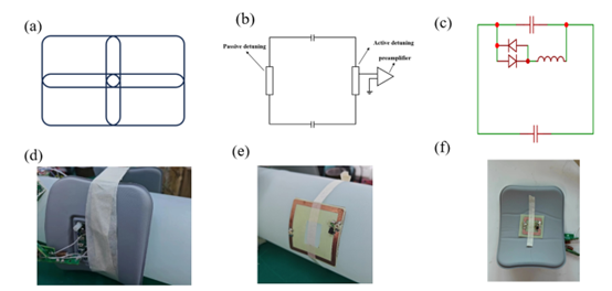
Figure 1 shows the layout, circuit schematics and the photographs of the 8-channel carotid array with two wireless resonators insert. The receiver coil elements were rectangular, with dimensions of 9cm in length and 6cm in width. The conductive trace had a width of 5mm. As shown in the circuit schematic of the receiver coil, a passive detuning circuit was included and placed at the opposite position of the active detuning circuit to further reduce transmit field distortion that was caused by receiver array. Cable traps were added on the cable of the receiver array to diminish the common mode current on the cable shield. Figure 1c shows the circuit schematic of the wireless resonators insert. A passive detuned circuit was included in the circuit. As a result, the wireless resonators insert was implemented as a resonant unit to enhance the receive field. The square wireless resonators insert were investigated with sizes of 30 mm, 40mm, 50 mm and 60 mm. Figure 1f shows the relative position of the carotid array and the wireless resonators insert. Each half of the carotid array included a wireless resonators insert. The B1+ maps and SNR maps were acquired on a cylinder phantom with a diameter of 100 mm. The B1+ maps were obtained using the self-developed dual refocusing echo acquisition mode (DREAM) sequence with the following parameters: TR/TE=1000/1.5ms, flip angle=54.7°, FOV=250mm×250mm. a two-dimensional gradient echo(GRE_2D) sequence was applied for SNR maps with the following parameters: TR/TE=300/6.76ms, flip angle=30°, FOV=128mm×130mm. "For noise image acquisition, the flip angle was set to zero. SNR maps were calculated using the sum-of-squares method.Results
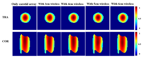
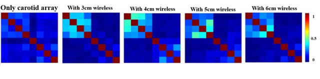
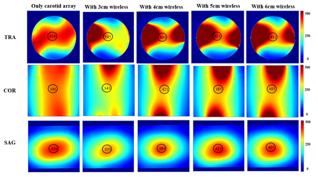
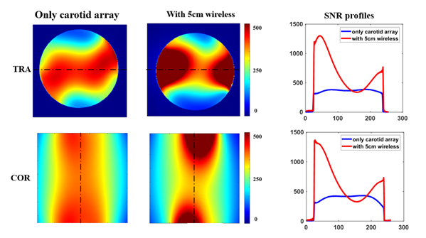
Figure 2 shows the B1+ maps with the only 8-channel carotid array and the 8-channel carotid array integrated with two wireless resonators insert in different sizes. From these maps, we can see that the B1+ field was barely affected after integrating with two wireless resonators insert. Figure 3 shows the noise correlation matrix. A discernible coupling effect was observed after integrating the wireless resonators insert. Figure 4 shows SNR comparisons using the only 8-channel carotid array and the 8-channel carotid array integrated with two wireless resonators insert in different sizes at 5T. The results show that the 8-channel carotid array integrated with two wireless resonators insert in a 50 mm size has the best performance in term of SNR. Figure 5 shows the SNR profiles using the 8-channel carotid array integrated with two wireless resonators insert in a 50 mm size and the only carotid array, from which we can know that the 8-channel carotid array integrated with two wireless resonators insert in a 50 mm size has much higher SNR than the only carotid array, up to 2-fold in the margin region.Discussions/Conclusions
In this study, we have constructed a novel 8-channel carotid array with two wireless resonators insert for 5T carotid vessel wall imaging. In the phantom study, the 8-channel carotid array integrated with two wireless resonators insert in a 50 mm size has much higher SNR than the only carotid array, up to 2-fold in the margin region. These findings hold significant implications, particularly in ultra-high-field magnetic resonance imaging. In the future work, head and carotid imaging of vessel walls will be implemented using a head coil [4] and the novel carotid array.Acknowledgements
This work was supported in part by the Project on Global Common Challenges of Chinese Academy of Sciences (No. 321GJHZ2022081GC); National Natural Science Foundation of China (Nos. U22A20344, 81830056, 62125111 and 52293425); Youth Innovation Promotion Association of CAS (No. Y2021098); the Key Laboratory for Magnetic Resonance and Multimodality Imaging of Guangdong Province(2023B1212060052; Shenzhen City Grant (No. RCYX20200714114735123).References
[1] Okada T, Fujimoto K, Fushimi Y, Akasaka T, Thuy DHD, Shima A, Sawamoto N, Oishi N, Zhang Z, Funaki T, Nakamoto Y, Murai T, Miyamoto S, Takahashi R, Isa T. Neuroimaging at 7 Tesla: a pictorial narrative review. Quant Imaging Med Surg. 2022, 12(6):3406-3435.
[2] Kraff O, Quick HH. Radiofrequency Coils for 7 Tesla MRI. Top Magn Reson Imaging. 2019, 28(3):145-158.
[3] Che S, Fang F, Dong K, Han S, li Y. Whole Spine Imaging at 5.0T Using An 8-channel Volume Transmit Coil and 48-channel Receive Array. Proc. 30th Annual Meeting of ISMRM, London, 2022, p3224.
[4] Tan Y, Chen Q, Xu G, Zhang L, Zhang N, Zhang X, Liu X, Zheng H, Li Y. A 48-channel head and neck neurovascular coil for MR vessel wall imaging at 5 T. Proc. 31th Annual Meeting of ISMRM, Toronto, 2023, p4227.
Figures