1607
Simulation of an 8-Channel Transmit Meander Stripline Array for Combined Head and Neck Imaging at 7 Tesla MRI1Erwin L. Hahn Institute for Magnetic Resonance Imaging, University Duisburg-Essen, Essen, Germany, 2Medical Physics in Radiology, German Cancer Research Center (DKFZ), Heidelberg, Germany, 3High-Field and Hybrid MR Imaging, University Hospital Essen, Essen, Germany, 4Institute of Electrical Engineering and Information Technology, South Westphalia University of Applied Sciences, Iserlohn, Germany, 5Institute of Electrical Engineering and Information Technology, FH Aachen – University of Applied Sciences, Aachen, Germany, 6Institute of Measuring and Sensor Technology, Ruhr West University of Applied Sciences, Mülheim a. d. Ruhr, Germany, 7RAPID Biomedical GmbH, Rimpar, Germany
Synopsis
Keywords: High-Field MRI, High-Field MRI, Head & Neck/ENT, coil arrays
Motivation: Covering the head-neck region in UHF MRI is challenging due to the limited number of only 8 parallel transmission (pTx) channels available in most UHF MR systems.
Goal(s): Our goal was to design and simulate an 8-channel pTx coil for combined head/neck imaging at 7T.
Approach: A geometrical setup for MR imaging with modified stripline elements was investigated by simulating the B1+ efficiency in a heterogenous tissue model.
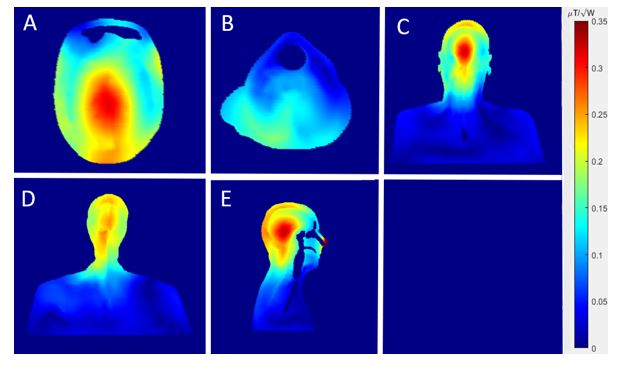
Results: B1+ efficiency maxima of 0.31 μT/√W for head region and 0.13 μT/√W for neck region with SAR10g maximum of 1.21 W/kg for 1W stimulated input power per channel could be achieved.
Impact: Meander stripline elements can be overlapped while showing only low coupling, allowing a good coverage of the head-neck area while only using 8 pTx elements in total.
Introduction
As the Larmor frequency increases the RF wavelength of MRI in human tissue shortens, which leads to interference effects and a limited penetration depth into the human body compared to lower MRI field strengths.1,2 A combined head-neck RF transmit (Tx)-array at 7T is highly anticipated and first design concepts have been presented, e.g., a 16-channel Tx-loop array.3 However, most current 7T systems are equipped with only 8 Tx-channels for parallel transmission (pTx). These systems have special requirements in terms of RF coil design to efficiently cover the rather large and curved head-neck region. Dipole-like coils are superior to resonant loop coils in terms of generating B1+ fields in the far-field region but produce higher levels of specific absorption rate (SAR) compared to loop coils with the same amount of input power.1,4 Thus, meander stripline elements (MSL) have been established as a robust and efficient design concept for 7T RF coils.5,6In this simulation study we investigate the possibility of using eight Tx MSL elements for combined head-neck imaging at 7T.
Methods
A MSL element with 250mm length, 100mm width and 1mm thickness was simulated using a meander size of 16.25mm width in radial length and a width of 2mm. The gap between each meander is 2mm. The eight MSL elements in transaxial orientation were curved to a degree of 22.5° to adapt to the morphological shape of the human head-neck region to improve positioning (Fig. 1). Eight elements were used, of which six elements were placed around the head (angles: 0°, 65°, 130°, 180°, 230°, 295°) with their longitudinal center at the level of the thalamus. Two additional elements were placed underneath the neck region (angles: 11.5°, 348.5°). To ensure combined head-neck imaging, both neck elements were overlapped in z-direction with the occipital head elements by a length of 50mm and by 35mm in x-direction. The distance between the occipital element 1 in the head and posterior elements 7 and 8 in the neck was 8.5mm in y-direction (Fig. 2). Simulations were performed by using CST Studio Suite (Dassault Systèmes, Vélizy-Villacoublay, France) to simulate the fields and the 10g-averaged local SAR in a male model (‘Gustav’, 176cm, 69kg, Dassault Systèmes). The S-parameters were optimized by adjusting the capacitor values in a circuit simulator’s tuning and matching network. The SAR and power efficiency were derived from the B1+ and SARmax values in CST. The simulations were driven in CP+ mode with 1W stimulated input power per channel.Results
All elements were tuned to better than -36dB reflection. Coupling between the head elements was found <-16.5dB, while a slightly higher but still acceptable coupling was found between the head and neck elements (S1,7 = -12.1dB and S1,8 = -14.6dB, see Fig. 3) due to the overlap of both neck elements with the posterior head elements.In CP+ mode, the array showed a B1+ efficiency in the center of the brain with a maximum 0.31μT/√W which decreased towards peripheral regions. Positioning of two elements to the neck extended the B1+ field in this region, delivering an average value of 0.13μT/√W in the posterior part of the neck (Fig. 4).
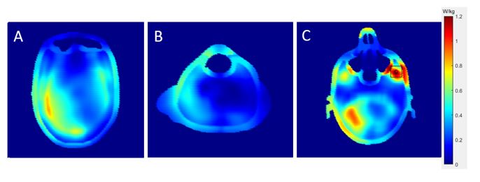
The SAR10g maximum for the model was 1.21W/kg located behind the right cheekbone (Fig. 5C).
Maximum permitted input power7 in normal mode was 8.26W for each channel, delivering values varying between 0.8 - 2.7μT from neck to head.
Discussion
The design concept extended the B1+ field for head imaging caudally to the neck area with only 8 MSL elements, which is a requirement for a standard 8-channel 7T MR system. Due to the unequal distribution of elements around head/neck, the overall B1+ field decreased towards the neck region and became more inhomogeneous. However, some compromises must also be made in terms of the degrees of freedom compared to an array with 8 channels dedicated to the neck area alone.3 Nevertheless, the B1+ efficiency in the neck area should be subject of further improvements. Potential solutions may be an increase of input power for the neck elements, which seems feasible under the given SAR constraints that allow sufficient RF power per channel. Adjustments on the phase shimming and the amplitudes and changing FR-4 to Rogers as substrate material will also be considered in this context. Based on the obtained results a prototype coil will now be constructed and compared to other arrays.Conclusion
The proposed coil shows promising results for combined head-neck imaging with an 8-channel pTx system for 7T MRI, extending the field of view from the brain towards the cervical spine.Acknowledgements
No acknowledgement found.References
[1] Orzada S, Quick HH, Ladd ME, et al. A flexible 8-channel transmit/receive body coil for 7 T human imaging. Proc Intl Soc MRM. 2009;17: 2999
[2] Raaijmakers, A & Lagendijk, J & Klomp, D & Bergen, Bob & Possanzini, Cecilia & Harvey, Paul & Berg, C. Boosting B 1 + efficiency for RF transmit surface elements by a radiative antenna design. Proc. Intl. Soc. Mag. Reson. Med. 17 (2009): 4764
[3] May, MW, Hansen, S-LJD, Mahmutovic, M, et al. A patient-friendly 16-channel transmit/64-channel receive coil array for combined head–neck MRI at 7 Tesla. Magn Reson Med. 2022; 88(3): 1419-1433.
[4] Raaijmakers AJ, Luijten PR, van den Berg CA. Dipole antennas for ultrahigh-field body imaging: a comparison with loop coils. NMR Biomed. 2016 Sep;29(9):1122-30.
[5] Rietsch SHG, Quick HH, Orzada S. Impact of different meander sizes on the RF transmit performance and coupling of microstrip line elements at 7 T. Med Phys. 2015 Aug;42(8):4542-52.
[6] Kraff O, Quick HH. Radiofrequency Coils for 7 Tesla MRI. Top Magn Reson Imaging. 2019 Jun;28(3):145-158.
[7] IEC 60601-2-33:2022, Medical electrical equipment - Part 2-33: Particular requirements for the basic safety and essential performance of magnetic resonance equipment for medical diagnosis; 2022
Figures
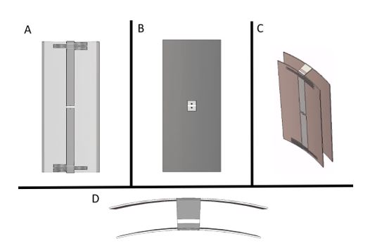
Figure 1: Geometry of the MSL antenna, curved by 22.5°. Both FR-4 substrate planes have a size of 250 mm x 100 mm x 1 mm. The conducting planes consist of a stripline structure with a meander size of 16.25 mm in radial length and a width of 2 mm, continued by a stripline with size of 109 mm x 15 mm (A, C) and a groundplane with a size of 250 mm x 100 mm (B). Connection of the two planes via capacitors placed in both gaps at the end of the antennas (D). A: Frontal view, B: Rear view, C: Diagonal view, D: Top view
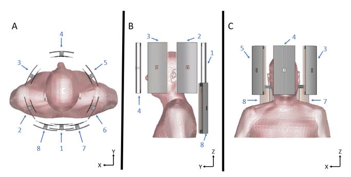
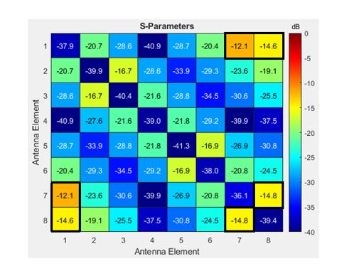
Figure 3: S-Parameter matrix for the 8-channel MSL antenna array loaded by an anatomical body model at f = 297.15 MHz. The coupling of the overlapping elements (S17 = -12.1 dB, S18 = -14.6 dB) and both neck elements (S78 = -14.8 dB) show the highest coupling values (black frames).