1606
Optimizing the element numbers to improve dipole antenna array for 14 Tesla MRI1College of Future Technology, Peking University, Beijing, China, 2School of electronics, Peking University, Beijing, China, 3Institute of Biomedical Engineering, Peking University Shenzhen Graduate School, Shenzhen, China
Synopsis
Keywords: RF Arrays & Systems, Simulations, Antenna array
Motivation: The multi-channel RF coil scheme for 14T head imaging has not been defined yet.
Goal(s): Our goal was to optimize the number of elements in the dipole antenna array in order to achieve optimal performance at 14T.
Approach: We obtained the $$$\text{B}_{1}^{+}$$$ field distributions and SAR distributions of dipole antenna arrays with 8, 12, 16, and 20 channels through electromagnetic simulation, and compared their performances.
Results: The results showed that the 12-channel dipole antenna array exhibits superior performance.
Impact: The number of channels in an RF coil at ultrahigh fields requires a trade-off between RF field uniformity and inter-cell coupling; 12-channel dipole antenna array serves as a suitable reference coil for 14T head imaging.
Introduction
At ultra-high fields, the increased frequency causes the wavelength of electromagnetic waves in brain tissue to significantly decrease compared to the size of the human head1. Consequently, the imaging location shifts from the near field to the far field region of the radio frequency (RF) antenna2. Dipole antennas, known for their simple structure and high transmitting efficiency, have gained significant attention as a representative far-field antenna. Recently, dipole antenna arrays have demonstrated excellent performance in ultra-high field MRI systems exceeding 7T3,4. A crucial challenge in ultra-high fields is the issue of inadequate RF uniformity. Enhancing uniformity can be achieved by increasing the number of channels through RF shimming5. However, this approach can amplify the coupling between units, resulting in energy loss6. Consequently, a trade-off exists between achieving high RF field homogeneity and low mutual coupling. This study employs electromagnetic(EM) simulations to calculate the S-parameters, $$$\text{B}_{1}^{+}$$$ field distributions, and SAR value of dipole antenna arrays with 8, 12, 16, and 24 channels. The objective is to compare the performance of these arrays and determine the dipole antenna array that exhibits the highest performance in 14T system.Method
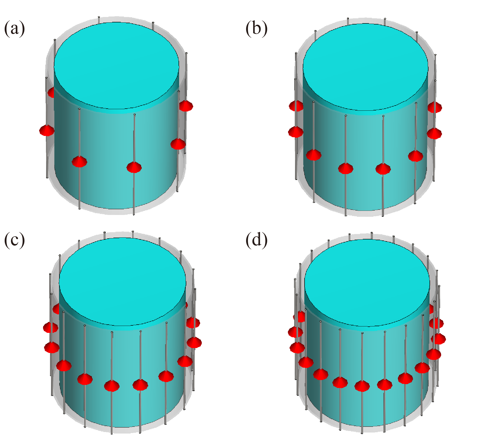
The designed multi-channel dipole antenna arrays are shown in Fig. 1. For all of the arrays, dipole antennas are evenly distributed on a coil holder with a 230 mm diameter. Each dipole antenna has a diameter of 3 mm and a length of 225 mm. A uniform cylindrical phantom of which the electrical properties mimic the human brain($$${{\varepsilon }_{r}}$$$=47.52, $$$\sigma$$$=0.66 S/m) was placed on the center of the dipole antenna array. Numerical simulations and analysis of the dipole antenna arrays were conducted by Computer Simulation Technology, (Darmstadt, Germany). A Time-domain solver was employed, and the solver accuracy was set to -50 dB in the EM simulations. Boundaries of the RF coil models were all set to open, and the bandwidth was set to 580–620 MHz. The performance the dipole antenna arrays were evaluated by the S-parameters, $$$\text{B}_{1}^{+}$$$ field, and SAR in the EM simulations. To achieve circularly polarized (CP) mode, an equal 1W power was applied to all channels with a phase shift. The value of $$$\text{B}_{1}^{+}$$$ fields and 10g SAR were calculated based on the simulated power normalized to 1 W.Results
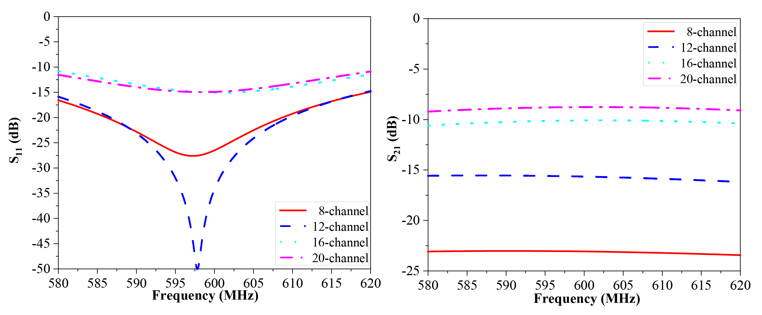
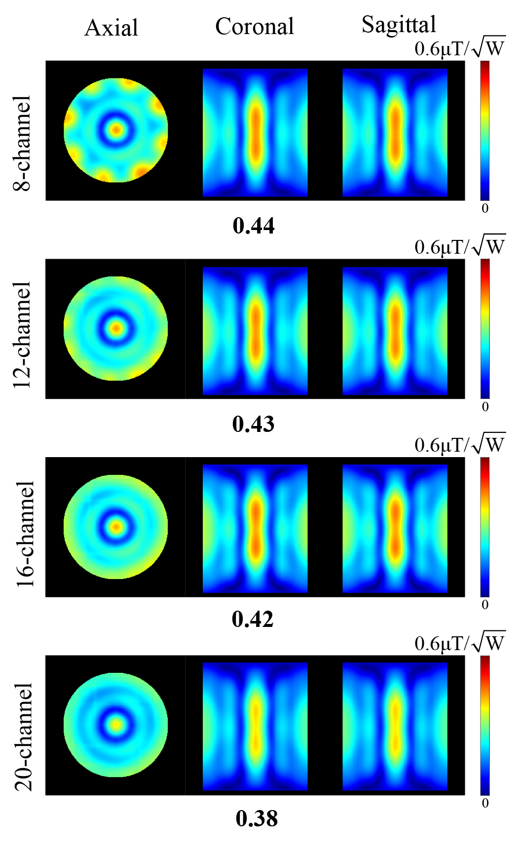
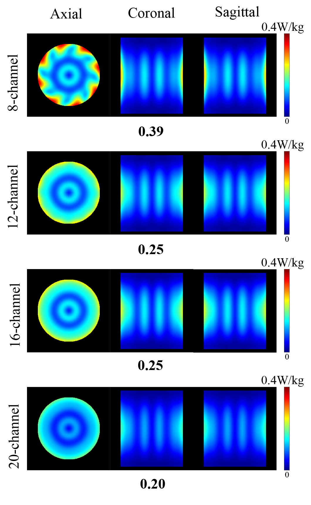
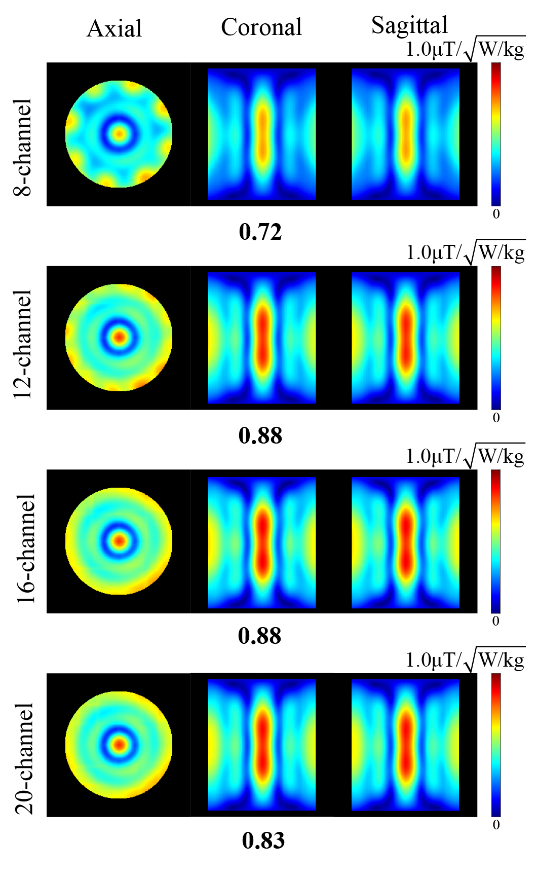
The reflection coefficient(S11) and coupling coefficient between neighboring elements(S21) of the different dipole antenna arrays are shown in Fig 2. The S11 of the four arrays at 596MHz was approximately -27 dB in 8-channel, -40 dB in 12-channel, -15 dB in 16-channel, and -15 dB in 20-channel,respectively which indicated that all of the dipole arrays have an acceptable tuning and matching effect. 8-channel array and 12-channel array show better decoupling performance with S21 below -15 dB. S21 was around -10 dB for 16-channel array and about -8.5 dB for 20-channel array , indicating severe coupling of neighboring antenna units. The simulated $$$\text{B}_{1}^{+}$$$ efficiency, 10g SAR and SAR efficiency of the 8-channel, 12-channel, 16-channel, 20-channel dipole arrays were calculated and shown in the Fig.3, Fig.4, Fig.5, respectively. The highest B1+ efficiency, 10g SAR, and SAR efficiency are indicated below the figures.Discussion
Figure 2 demonstrates a notable increase in S21 with an increasing number of channels. This can be attributed to the increased coupling resulting from the proximity of neighboring elements as the number of antennas increases. Observation of Figure 3 reveals the inhomogenity of the 8-channel array, the low $$$\text{B}_{1}^{+}$$$ efficiency of the 20-channel array, and the closely comparable results of the 12- and 16-channel arrays. Figure 4 shows a decrease in the local SAR value as the number of elements increases, with almost identical results for the 12- and 16-channel arrays. Figure 5 demonstrates the higher SAR efficiency of the 12- and 16-channel arrays compared to the other arrays. The results indicate that the 12-channel and 16-channel arrays exhibit similar $$$\text{B}_{1}^{+}$$$ and SAR indexes. However, the 16-channel array experiences coupling issues between neighboring channels, resulting in some degree of energy loss. Therefore, 12-channel dipole antenna array demonstrates superior performance.Conclusion
The number of channels in the dipole antenna array at 14T was optimized to determine the optimal RF coil scheme. Simulations were conducted to assess the performance of dipole antenna arrays with 8, 12, 16, and 20 channels, evaluating their S-parameters, $$$\text{B}_{1}^{+}$$$ field, and SAR values. Our findings indicate that the 12-channel dipole antenna array exhibited the superior performance. In future work, further improvement in RF field uniformity can be achieved through RF shimming techniques.Acknowledgements
This work was supported by the Research and Development of Key Technologies and Equipment for Major Science and Technology Infrastructure of Development and Reform Commission of Shenzhen Municipality, China (Grant No. ZDKJ20190305002).References
1. Yang, Q. X., Wang, J. , et al. Analysis of wave behavior in lossy dielectric samples at high field. J. Magn. Reson.2002; 47(5), 982–989.
2. Woo MK, Delabarre L, Waks M, et al. Comparison of 16-Channel Asymmetric Sleeve Antenna and Dipole Antenna Transceiver Arrays at 10.5 Tesla MRI. IEEE Trans Med Imaging. 2021;40(4):1147-1156.
3. Raaijmakers, A. J. E., Ipek, et al. Design of a radiative surface coil array element at 7 T: The single-side adapted dipole antenna. Magnetic Resonance in Medicine.2011; 66(5), 1488–1497.
4. Ertürk, M. A., Wu, X., et al. Toward imaging the body at 10.5 tesla. Magnetic Resonance in Medicine.2016; 77(1), 434–443.
5. Mao, W., Smith, M. B., & Collins, C. M. Exploring the limits of RF shimming for high-field MRI of the human head. Magnetic Resonance in Medicine.2006;56(4), 918–922.
6.Winter, L., & Niendorf, T. Electrodynamics and radiofrequency antenna concepts for human magnetic resonance at 23.5 T (1 GHz) and beyond. Magnetic Resonance Materials in Physics, Biology and Medicine.2016; 29(3), 641–656.
Figures