1605
A Birdcage Volume Transmit coil and 8 Channel Receive Array for Marmoset Brain Imaging at 7T1McConnell Brain Imaging Centre, Montreal Neurological Institute and Hospital, McGill University, Montreal, QC, Canada, 2Department of Neurology and Neurosurgery, McGill University, Montreal, QC, Canada, 3Siemens Healthcare Limited, Montreal, QC, Canada, 4Integrated Program in Neuroscience, McGill University, Montreal, QC, Canada, 5McConnell Brain Imaging Centre, Montreal Neurological Institute and Hospital, Montreal, QC, Canada, 6Department of Biomedical Engineering, McGill University, Montreal, QC, Canada, 7Azrieli Centre for Autism Research, The Neuro, Montreal, QC, Canada
Synopsis
Keywords: RF Arrays & Systems, Animals, Marmoset, High Field MRI, 7T
Motivation: 7T promises a high SNR for high-resolution imaging of the small marmoset brain, which requires a custom RF coil.
Goal(s): To develop a robust marmoset coil for 7T with an efficient volume transmit and receive array with a very high density and high filling factor.
Approach: The coil was constructed, consisting of a volume transmit coil and receive array of 8 receive-only loops. The coil was tested with a phantom and a single anesthetized marmoset.
Results: The transmit coil along with the optimized receive array for imaging the whole marmoset brain has been shown to produce images of high resolution and high SNR.
Impact: A shielded, band-pass birdcage transmit coil was designed and fabricated for marmoset brain imaging at 7T. An 8-channel receive array consisting of eight overlapped loops covering the whole brain of the marmoset was also built and applied for signal reception.
Introduction
The common marmoset (Callithrix jacchus) is an ideal model for studying brain structure and function because of its close homology with humans [1].For marmoset brain imaging at 7T, A local transmitter and a receive array with small coils/loops close to the marmoset head [2, 3] are essential. Here we present a combination of a volume transmit (Tx) coil and an 8 channel high density receive (Rx) array for marmoset brain imaging at 7T using Siemens MAGNETOM Terra scanner.
Materials and Methods
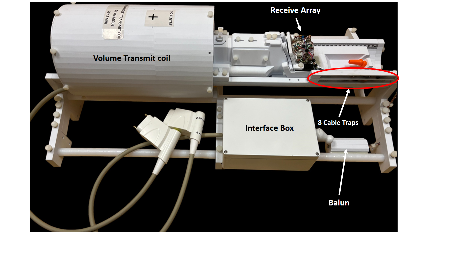
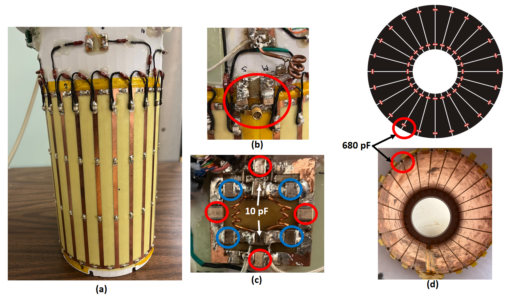
The coil consists of a volume transmit coil, receive array with 8 independent receive-only loops, 8 cable traps, a Balun and an interface box (Fig 1).Transmit coil: The volume transmit coil consists of a band-pass birdcage, shielded from the outside, and a quadrature hybrid (Fig.2). The transmit coil has a diameter of 15 cm and 24 legs with lengths of 25 cm. Two 9 pF capacitors were included for each leg and 46 end-ring capacitors (15pF) were also applied between each two legs (top and bottom). The PIN diodes were used for active detuning. Two 35 pF capacitors and one high power variable capacitor (Fig 2.a) were used for matching circuit. The quadrature hybrid in Fig 2.c was used to create the circular polarized RF excitation for the birdcage. Four 680 pF capacitors (red circles in Fig 2.c) and four 5pF capacitors (blue circles in Fig 2.c) were used in quadrature hybrid. Fig 2.d shows the RF shield. The RF shield had a diameter of 20 cm and forty-eight 680 pF capacitors were used to mitigate the eddy current.
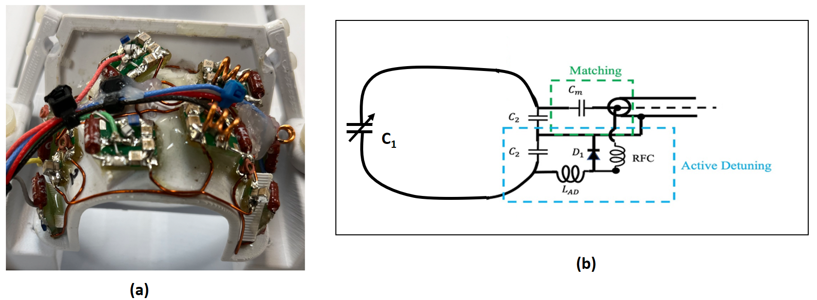
Receive Array: The marmoset brain receive array, shown in Figure 3, consisted of an 8-element Rx phased array with varying loop shapes and sizes (2-4 cm diameters) built onto a custom, 3D printed marmoset head former [4]. Each Rx loop in Fig. 2 was tuned to 297.2 MHz and was built with an active detuning circuit. One cable trap was also used between each loop and the Balun (8 cable traps, in total, shown in Fig. 1)
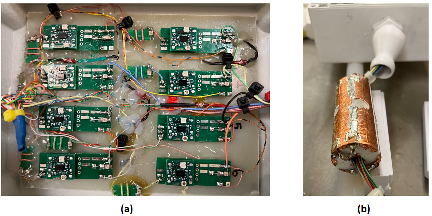
Interface Box and Balun: Eight “Wan Tcom“ preamplifiers [5] were incorporated into the interface box for signal amplification. An extra balun was also used for 8 receive coax cables before the interface box (balun shown in Fig. 1). Fig 4 shows the interface box and the balun.
Experimental imaging results were collected using the transmit coil with the receive array using a 7T whole body MR system (Siemens Terra 7T, sTx mode). All experimental methods described were performed in accordance with the guidelines of the Canadian Council on Animal Care policy on the care and use of experimental animals and an ethics protocol #10000 approved by the Animal Care Committee of the Neuro. Data have been collected in an adult anesthetized marmoset (512g, 4.5 years old). Anesthesia has been induced by intramuscular injection of Alfaxalone and maintained with isoflurane through endotracheal intubation during all the imaging acquisition. Animal’ vitals (SPO2, heart rate, respiration, temperatures) were monitored by animal health technicians using model 1040 MR from SA Instruments, Inc. The animal was in a sphinx position.
Results and Discussions
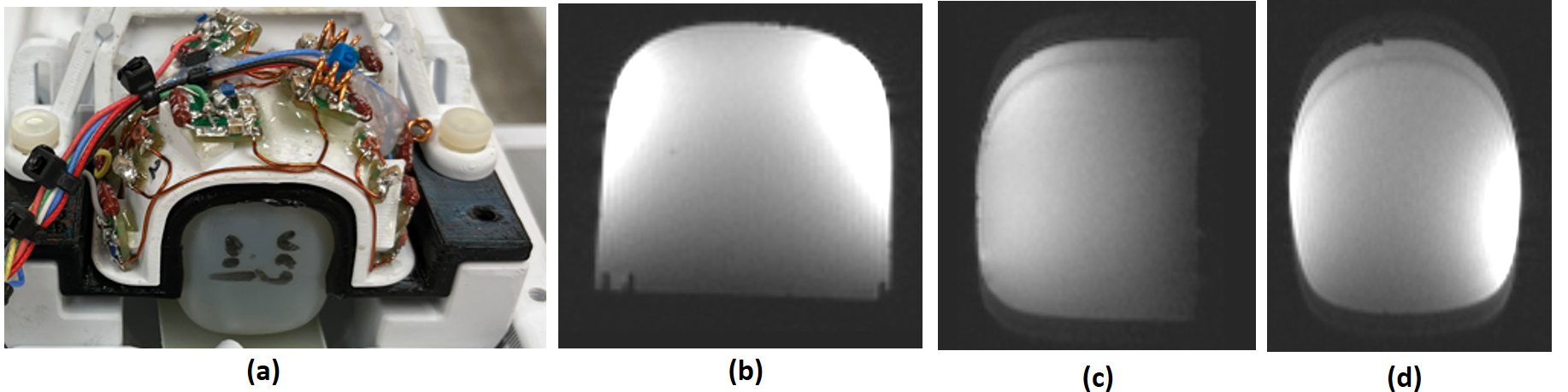
The coil was tested by imaging a small marmoset brain phantom (composed of water, cross-sectional dimensions = 3cm x 3cm) shown in Fig. 5a and by imaging a marmoset in vivo (Fig 6.a).The S11 (reflection coefficient) of the birdcage was -20dB and the B1- efficiency was 16 µT/sqrt (kW) when loaded with the small phantom.
The 8 receive loops had S11 values between -15dB and -25dB and S21 values between -10dB and -25dB. The Q-ratio (Qu/QL) of the Rx elements varied from 3.5 to 5.8 using the small water phantom. Fig. 5b, Fig. 5c and Fig. 5d show the 2D spoiled gradient echo images using the small marmoset brain phantom (Fig. 5a).
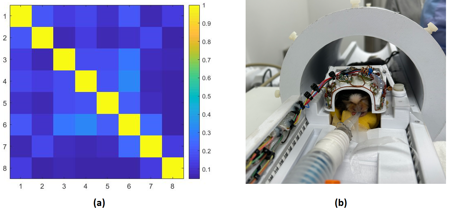
Fig. 6a shows the noise correlation matrix for the eight receive loops when an anesthetized marmoset subject was used (Fig 6b), with a mean of 13% and a max of 32%.
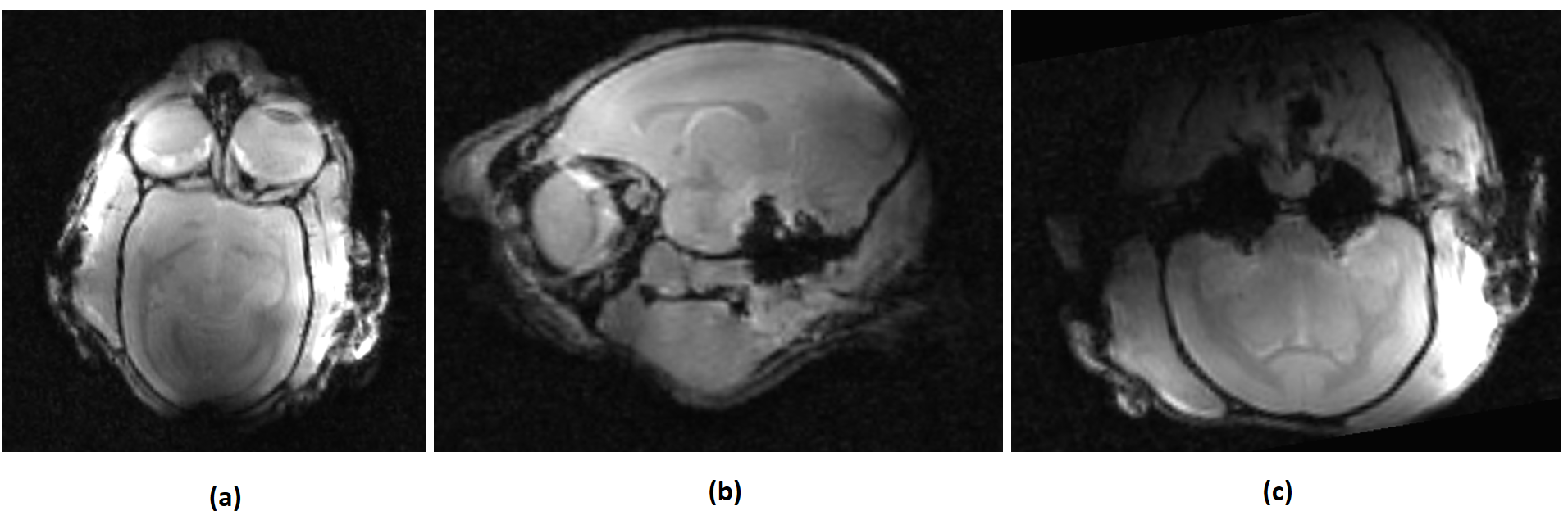
Fig 7 shows the in vivo, anatomical 3D GRE images for the anaesthetized marmoset subject displayed in Fig 6b.
Conclusion
A combination of a volume transmit coil and an 8 channel receive array was constructed and evaluated for marmoset brain imaging at 7T. The transmit coil, along with the optimized receive array for imaging the whole marmoset brain, has been shown to produce images of high resolution and high SNR. This non-invasive system will be essential for conducting neurodevelopmental and longitudinal studies in control and disease models in the marmoset.Acknowledgements
Support was provided by McGill University (Start-up fund), Natural Sciences and Engineering Research Council of Canada (NSERC) Discovery Grant program (NSERC DGECR-2023-00048), Canadian Foundation for Innovation and by the McConnell Brain Imaging Centre through Brain Canada.
Research Support from Siemens Healthineers Limited is gratefully acknowledged. We thank also Kyle M. Gilbert (Centre for Functional and Metabolic Mapping, Western University, London, ON, Canada) for his valuable support.
References
[1] Okana, et al: The common marmoset as a novel animal model system for biomedical and neuroscience research applications, Seminars in Fetal and Neonatal Medicine, Volume 17, Issue 6, December 2012, Pages 336-340
[2] Roemer PB, et al, “ The NMR Phased Array”, Magn Reson Med 1990, 16: 192-225
[3] Massner JA, et al “An adjustable 8-channel coil array for MRI of human wrist”, Proc Intl Soc Magn Reson Med 2006, 14:416
[4] Gilbert KM, et al “A radiofrequency coil to facilitate task-based fMRI of awake marmosets”, J. Neurosci. Methods. 2023;383 doi: 10.1016/j.jneumeth.2022.109737
[5] https://www.wantcominc.com
Figures