1603
A wireless resonator layer for high-resolution TMJ MRI at 1.5 T1Research center, Sino Canada Health Institute Inc., Winnipeg, Manitoba, Canada, Winnipeg, MB, Canada, 2Physical Examination Center, The Affiliated Hospital of Inner Mongolia Medical University, Hohhot, China, 3Sino Canada Health Engineering Research Institute (Hefei) Ltd, Hefei, China, 4Hubei Key Laboratory of Intelligent Conveying Technology and Device, Hubei Polytechnic University, Huangshi, China, 5Department of Radiology and Radiological Sciences, Vanderbilt University Medical Center, Nashville, TN, United States, 6Department of Physics, The University of Winnipeg, Winnipeg, MB, Canada, 7Vanderbilt University Institute of Imaging Science, Vanderbilt University Medical Center, Nashville, TN, United States, 8Department of Electrical and Computer Engineering, Vanderbilt University, Nashville, TN, United States
Synopsis
Keywords: RF Arrays & Systems, RF Arrays & Systems, TMJ, MRI, wireless coil, SNR, detune, RF coil
Motivation: Most imaging facilities lack specialized coils, resulting in suboptimal TMJ MRI scans using head receive array.
Goal(s): Developing flexible, cost-effective and efficient accessories to enhance TMJ MRI image using existing facilities.
Approach: Improve TMJ MRI scans by incorporating an inductive wireless resonator insert into a head array. evaluating its performance against the head array alone using phantom and in vivo imaging.
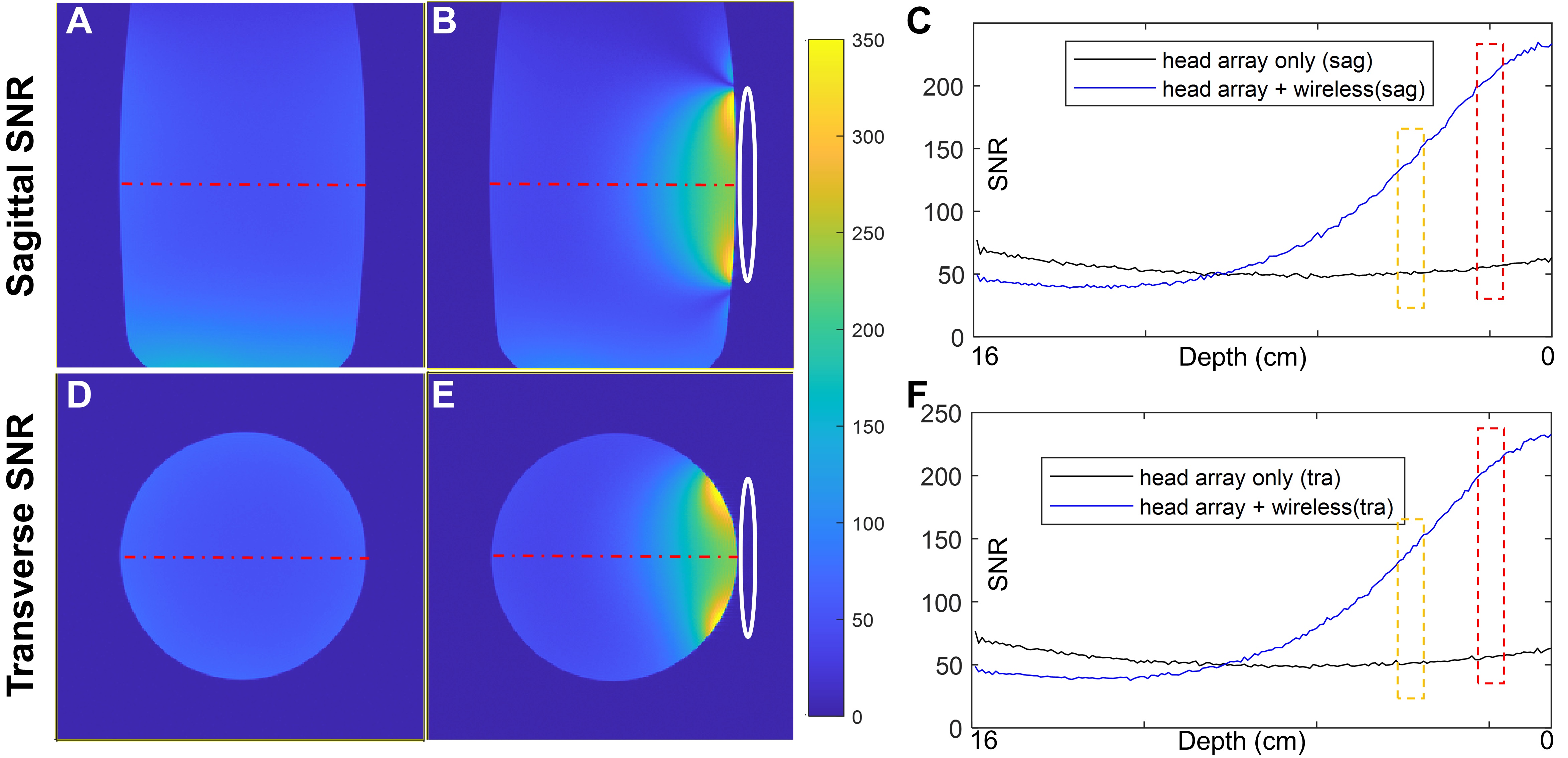
Results: The SNR increases by 5.3-fold times at the TMJ's articular fossa area and remains 2.4-fold at a 4cm depth, using a wireless resonator insert and head array combination, compared to a phased array.
Impact: Combining wireless RF resonators and phased arrays transformed MRI coils technology. It enhancing SNR in specific regions like the thyroid and carotid artery, allowing parallel imaging . This advancement ensures affordability, well-workflow, and the adaptability to various magnetic field strengths.
INTRODUCTION
MRI provides highly detailed images that enable healthcare professionals to assess the joints and surroundings in great detail. While commercial MRI scanners typically come equipped with basic receive coils, such as the head receive array, RF coils tailored for specialized applications like TMJ MRI must be obtained separately. Consequently, TMJ MRI scans often use suboptimal head receive array 1-4 due to the lack of specialized coils. In this study, we introduce a simple, low-cost, and easy-to-reproduce wireless resonator insert to enhance the quality of TMJ MRI at 1.5 Tesla. The wireless resonator shows a significant improvement in SNR and noticeably better imaging quality compared to the head array alone in both phantom and in vivo images.METHODS
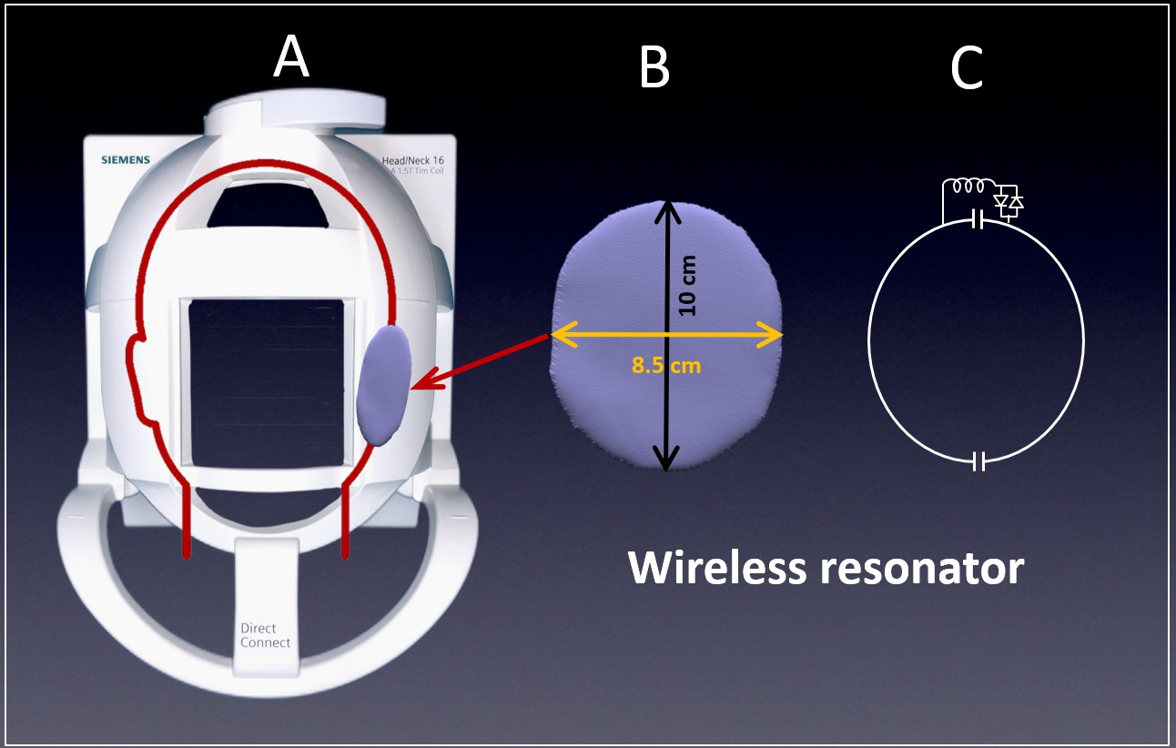
Figures 1A and 1B depict the head-neck receiver array and a wireless resonator, illustrating the positioning of the wireless resonator for TMJ MRI. Figure 1C depicts the circuit diagram of the wireless resonator which was tuned to 63.67 MHz, the passive detune circuit disables the wireless resonator during the transmit phase, similar to the designs in previous works 5-8 The centers of the wireless resonator pads are aligned with TMJ for optimal imaging performance. The body coil is used for RF transmission, while the head array is employed for RF reception. We perform multiple tests to assess the performance with and without the wireless resonator inserted into the head array:- The transmit field (B1+) map and RF power calibration for detuning effectiveness
- Phantom image for SNR measurement
- Volunteer image for clinical evaluation
RESULTS
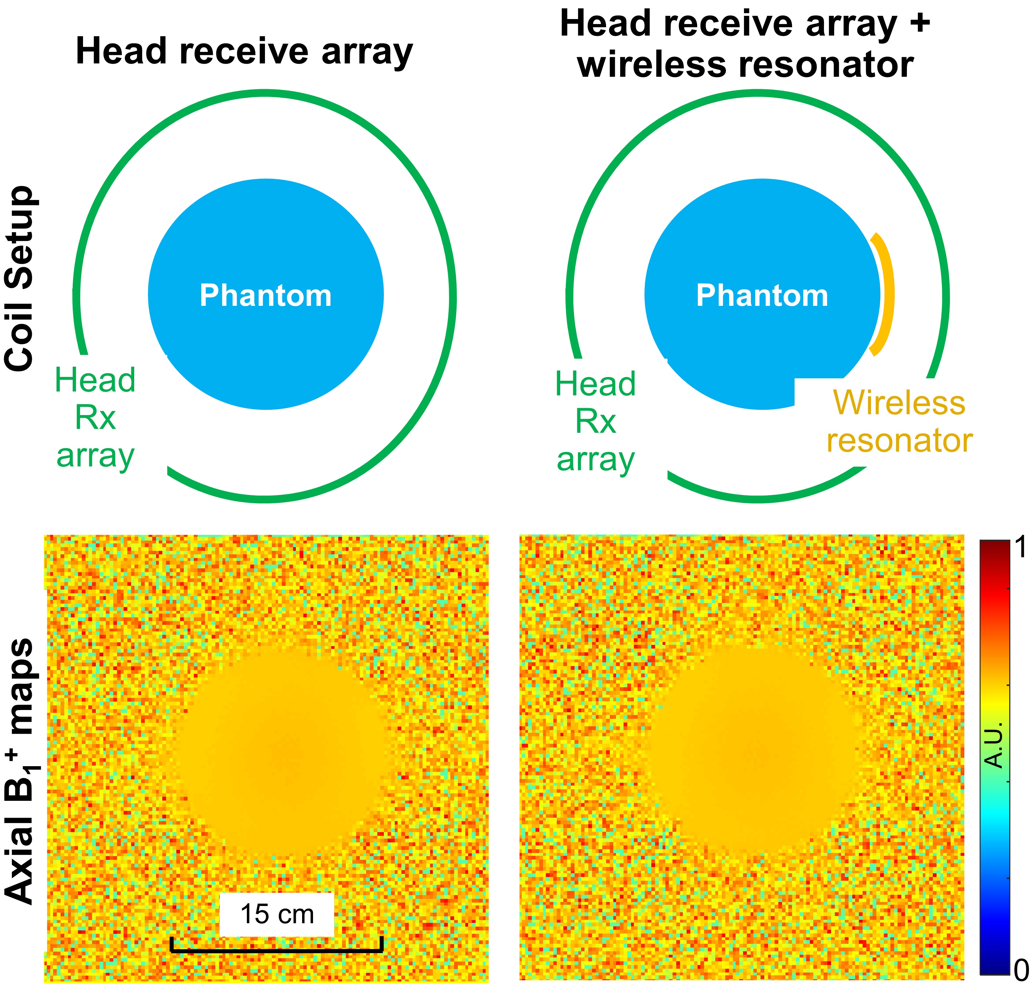
Figure 2 compares axial B1+ with and without the wireless resonator insert. The difference between these two B1+ maps is <1%. Additionally, The RF power change for a 180-degree flip angle was under 1.5% with and without the wireless resonator. These affirm that the wireless insert remains highly transparent to RF power during the transmit phase.In the context of TMJ MRI, where we typically focus on anatomical structures like the articular fossa, articular eminence, and disc, the average depth rarely exceeds 2.5 cm. The SNR improvement (averaged over the red box in Figures 3C and 3F) achieved with the wireless resonator can reach up to 5.3 times at this depth. the SNR (averaged over the yellow box in Figures 3C and 3D), remains 2.4 times even at a depth of 4 cm.
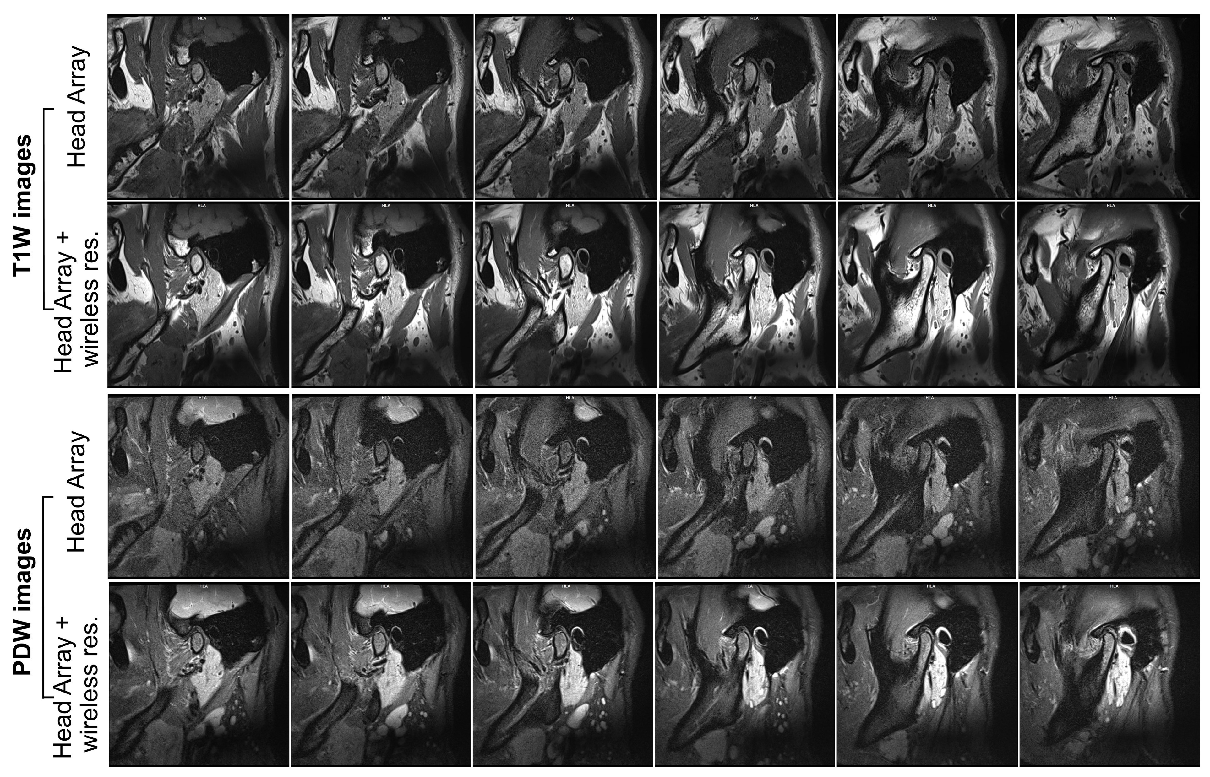
Figure 4 displays volunteer TMJ images, acquired using multi-slice sagittal T1-weighted and PWD images. Combining the wireless resonator with the head array significantly improves image quality over using the head array alone. This aligns with our phantom study, where the wireless resonator consistently provided higher SNR. To achieve acceptable quality with just the head array, thicker slices or longer scan times are necessary.
DISCUSSIONS
We chose the head array instead of the body coil as the primary coil for the following reasons:- It offers stronger mutual coupling, higher wireless power transfer efficiency, and lower coil loss.
- This choice combines large array coverage with high local SNR, aiding TMJ MRI localization.
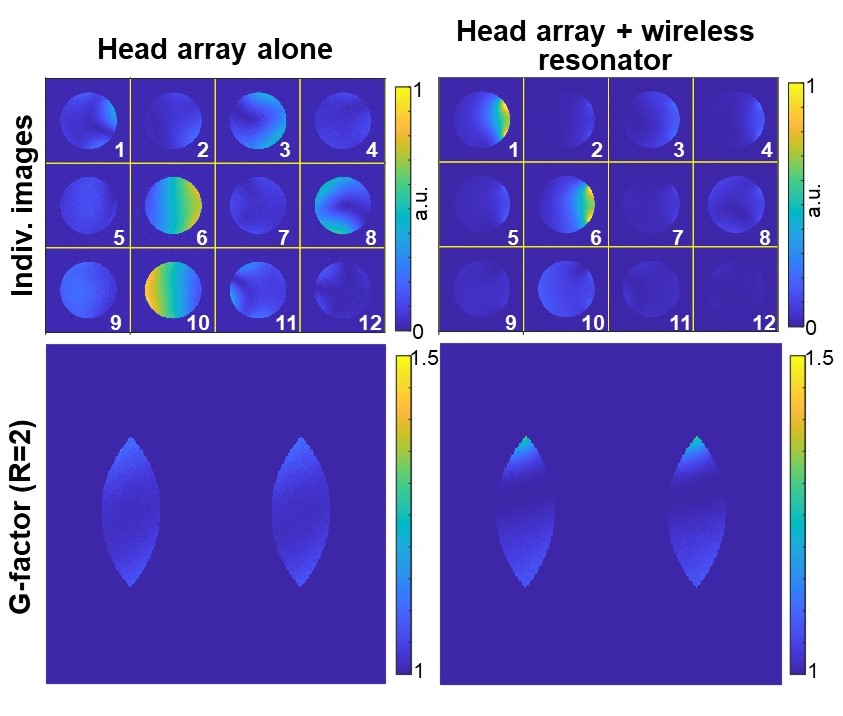
- Parallel imaging functionality. In Figure 5, the g-factor computations performed on a phantom with R-L acceleration factors ranging from 2 to 4. The comparison with g-factors obtained from a head array is also provided. The majority of commercially available TMJ coils do not possess parallel imaging capabilities.
CONCLUSION
The combination of wireless RF resonators and phased arrays enhances SNR in specific regions and enables parallel imaging within existing MRI setups.This approach could prove beneficial for imaging other anatomies, such as the thyroid, eye, and carotid artery. Different wireless RF resonators can also be integrated with diverse receive arrays to acquire extremity, breast, and body images tailored to specific anatomies.
Beyond using L/C resonators for wireless inserts, alternative solutions may involve volume-type wireless resonators or metamaterial-inspired designs.
Acknowledgements
No acknowledgement found.References
- D.T. dos Santos, M.G.P. Cavalcanti, Osteosarcoma of the temporomandibular joint: Report of 2 cases, Oral Surgery, Oral Medicine, Oral Pathology, Oral Radiology, and Endodontology. 94 (2002) 641–647. https://doi.org/10.1067/moe.2001.129181.
- R. Emshoff, K. Innerhofer, A. Rudisch, S. Bertram, Clinical versus magnetic resonance imaging findings with internal derangement of the temporomandibular joint: An evaluation of anterior disc displacement without reduction, Journal of Oral and Maxillofacial Surgery. 60 (2002) 36–41. https://doi.org/10.1053/joms.2002.29071.
- Y. Uchiyama, K. Matsumoto, S. Murakami, T. Kanesaki, A. Matsumoto, M. Kishino, S. Furukawa, MRI in a case of osteosarcoma in the temporomandibular joint, Dentomaxillofacial Radiology. 43 (2014) 20130280. https://doi.org/10.1259/dmfr.20130280.
- S. Krohn, N. Gersdorff, T. Wassmann, K.-D. Merboldt, A.A. Joseph, R. Buergers, J. Frahm, Real-time MRI of the temporomandibular joint at 15 frames per second—A feasibility study, European Journal of Radiology. 85 (2016) 2225–2230. https://doi.org/10.1016/j.ejrad.2016.10.020.
- H. Zhu, M. Fallah-Rad, M. Lang, W. Schellekens, K. Champagne, L. Petropoulos, A novel multichannel wireless receive phased array coil without integrated preamplifiers for high field MR imaging applications, in: ISMRM, 2012: p. 2788.
- H. Zhu, M. Fallah-Rad, L. Petropoulos, Wireless phased array endorectal coil for prostate imaging, in: 2013: p. 2732.
- M. Lu, S. Chai, H. Zhu, X. Yan, Low-cost inductively coupled stacked wireless RF coil for MRI at 3 T, NMR in Biomedicine. 36 (2023) e4818. https://doi.org/10.1002/nbm.4818.
- IEC 60601-1:2023 SER | IEC Webstore | electromagnetic compatibility, EMC, smart city, (n.d.). https://webstore.iec.ch/publication/2603 (accessed July 27, 2023).
- Manoliu, G. Spinner, M. Wyss, S. Erni, D.A. Ettlin, D. Nanz, E.J. Ulbrich, L.M. Gallo, G. Andreisek, Quantitative and qualitative comparison of MR imaging of the temporomandibular joint at 1.5 and 3.0 T using an optimized high-resolution protocol, Dentomaxillofacial Radiology. 45 (2016) 20150240. https://doi.org/10.1259/dmfr.20150240.
Figures