1598
Design of a Cryogenic RF Coil Prototype for a Full Body 1.5T MRI Receive Array1Technical University of Denmark, Kgs. Lyngby, Denmark, 2University Medical Center Utrecht, Utrecht, Netherlands, 3WaveTronica B.V., Utrecht, Netherlands
Synopsis
Keywords: New Devices, New Devices, Cryogenic coils; cryogenic preamplifiers; remote coils
Motivation: The MRI scanning procedure often relies on close-fitting RF coils to maximize signal-to-noise (SNR) ratio and assure image quality. Such an approach impairs patient comfort and requires qualified personnel, which increases the overall costs.
Goal(s): This study aims to avoid using close-fitting RF coils by integrating them in the bore of the scanner.
Approach: The coil is evaluated by developing a single element cryogenic coil prototype for a wide-bore 1.5T MRI system and with simulation to evaluate SNR and decoupling.
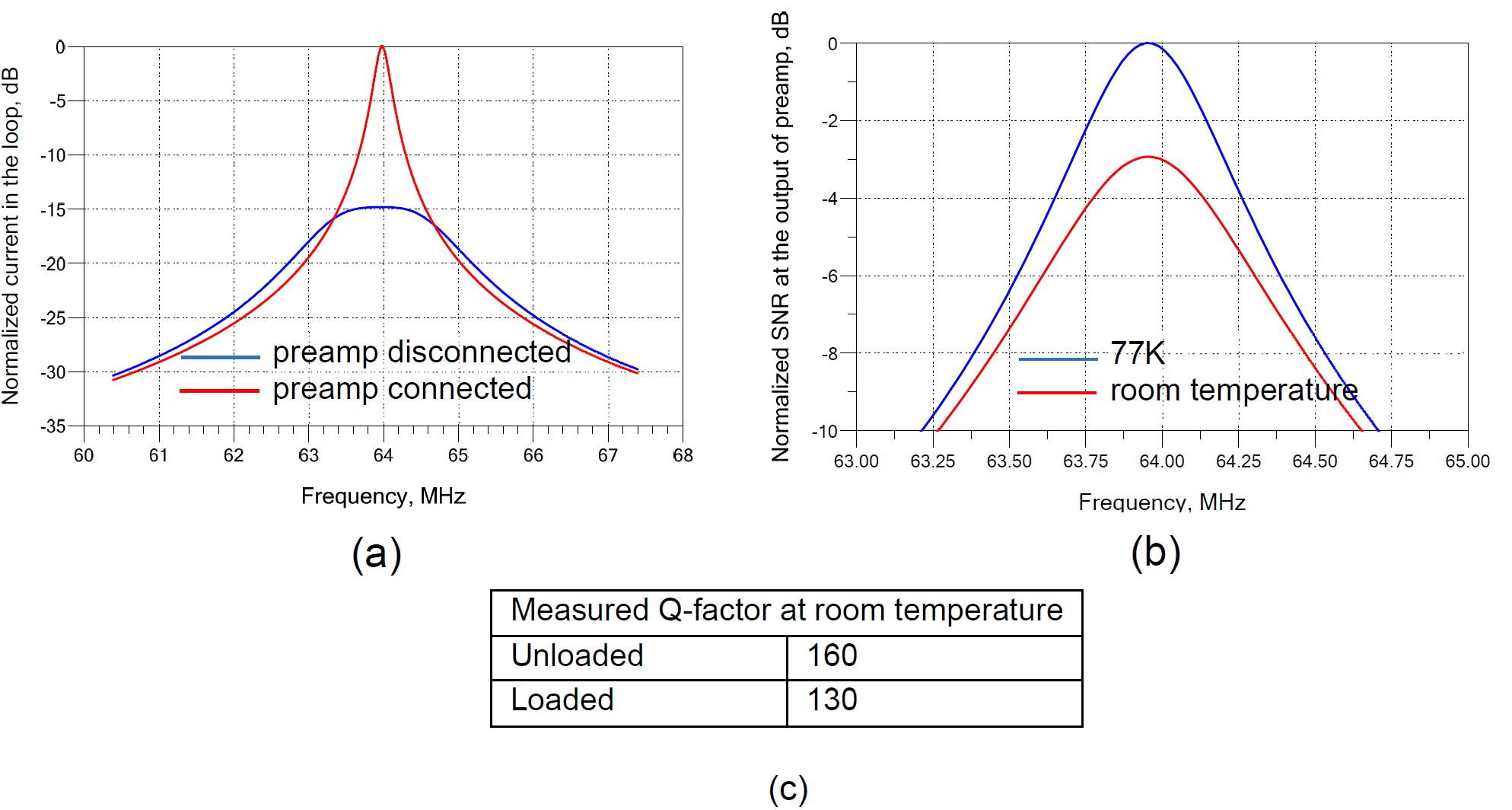
Results: Simulations indicate that the coil can achieve 15dB of preamplifier decoupling and that cooling results in a 3dB SNR improvement.
Impact: Avoiding close proximity and making RF coils invisible to a patient by integrating them into a bore of an MRI scanner will positively impact operating costs. While the signal strength is reduced, SNR can be partially regained by cryogenic cooling.
Introduction
An RF coil is the first component in the MRI scanner receiver chain. This component therefore defines signal-to-noise ratio (SNR) and influences image quality. The ultimate goal of MRI development has always been to increase SNR. As the name indicates, SNR increase can be achieved by increasing the signal level and by decreasing the noise. The majority of efforts in the history of MRI development have been focused on increasing the signal. This is the reason typical MRI scans often rely on close-fitting coils. From a usability perspective and for the comfort of the patient it is beneficial to eliminate close-fitting RF coils1 and make them virtually invisible by integrating them into the scanner bore. In this work, this approach is studied, and a prototype of an integrated coil is developed.Methods
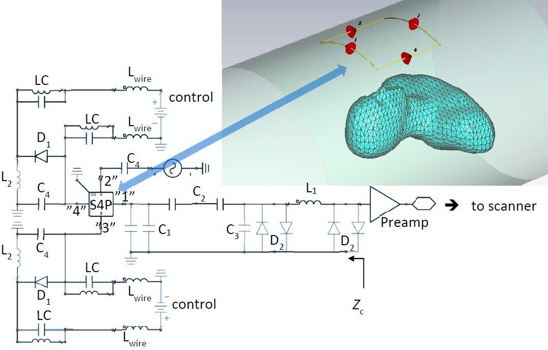
Placing RF coils further away from the patient reduces the received signal. To maintain SNR, the noise should be decreased accordingly. Apart from interference, there are two sources of noise in the receive coil. Intrinsic noise of the coil and the noise coming from the patient. The coil thermal noise can be reduced by cryogenic cooling, while patient noise can be reduced by shrinking the field of view. To recover the original field of view, the number of coils is increased forming an array of receive elements. The receive array can be shaped as a large cylinder conforming to the bore, as conceptually illustrated in Fig. 1, and complement a standard transmitting birdcage coil (not shown). Fig.1 also shows the resulting B1¯ field in one row of coils simulated with CST.To test the concept, one element of such a receive array is designed and constructed. The receiving element is placed very close to the transmitting birdcage coil2, which requires a reliable decoupling strategy. Two active decoupling circuits on the loop and a preamplifier decoupling circuit are used, as shown on the element block-diagram in Fig.1. The corresponding circuit diagram and simulation setup are shown in Fig.2. The field in the loop is analyzed with CST frequency domain solver using adaptive tetrahedral mesh refinement and a Virtual Family Duke v2 shell phantom3, 4. The corresponding scattering matrix is imported into Keysight ADS for circuit analysis. The preamplifier decoupling network is a three-element Pi network, which is based on the concept described in 5 and using design equations from 6, 7. The impedance of the preamplifier is extended with the reactance of L1. The preamplifier is ElCry2-u8 modified for cryogenic operation and noise pre-matched to 50Ω at ~63.9MHz using equations from 6, 7.
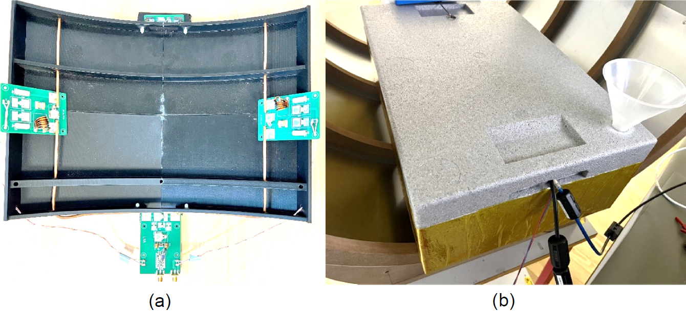
The coil is fabricated according to the design in Fig.2. The loop size is ~ 26cm x 27cm in the z- and x-directions correspondingly. It is constructed of the copper outer conductor of a .141CU-C-L-50 coaxial cable (3.58mm outer diameter). The coil holder was 3D printed. A photograph of the coil with the upper cover removed is shown in Fig.3(a).
Results
The impedance of the coil at the preamplifier terminals at room temperature as measured by a network analyzer was Zc≈42Ω (see Fig.2).For the analysis, it is assumed that the copper conductivity increases from 5.8·107 S/m to 2.86·108 S/m at 77K9. The loop wire resistivity and the loss of the implemented lumped components is assumed to decrease accordingly with a factor of ~4.9. The results of the preamplifier decoupling and SNR analysis are shown in Fig. 4.
Discussion and Conclusion
As expected, preamplifier decoupling decreases the signal current in the loop due to spoiling the coil resonator Q-factor. The decrease is about 15dB due to a high reflection coefficient at the coil terminals compared to the resonant case. Preamplifier decoupling, however, does not affect the SNR, since, along with the signal, the coil noise is also reflected, which maintains the overall sensitivity. Though the preamplifier decoupling is lower than one would typically expect from alternative room temperature commercially available preamplifiers. This is mainly due to the implemented preamplifier having additional integrated high-power protection circuits, since it is placed very close to the transmitter. The SNR improvement due to cooling is expected to be in the range of 3dB. This does not account for any preamplifier noise figure change due to cooling. The coil is currently being tested and the imaging results will be presented at the conference.Acknowledgements
The authors would like to thank Jóan Hofgaard Køtlum for PCB layout and fabrication.References
1. Sodickson, D.K., Zhang, B., Duan, Q., et al. Is a ’one size fits all’ many-element bore-lining remote body array feasible for routine imaging? Proc. Int. Soc. Magn. Reson. Med. 2014, 22, 618.
2. Branderhorst W., Steensma B., Beijst C., et al. Evaluation of the radiofrequency performance of a wide-bore 1.5 T positron emission tomography/magnetic resonance imaging body coil for radiotherapy planning. Physics and Imaging in Radiation Oncology. 17 (2021) 13–19.
3. Andreasen H.K. Design and Implementation of an 8-channel Array for High Field MRI. Bachelor’s thesis. Electromagnetic Systems, Department of Electrical Engineering. DTU, Ørsteds Plads, Building 348, 2800 Kgs. Lyngby Denmark. 2021.
4. Gosselin M-C., Neufeld E., Moser H., et al. Development of a new generation of high-resolution anatomical models for medical device evaluation: the Virtual Population 3.0. Physics in Medicine & Biology. 2014;59(18):5287.
5. Roemer P. B., Edelstein W. A., Hayes C. E., et al. The NMR phased array. Magnetic Resonance in Medicine. 1990;16(2):192-225.
6. Wang W., Zhurbenko V., Sanchez-Heredia J.D., Ardenkjær-Larsen J. H. Three-element matching networks for receive-only MRI coil decoupling. Magnetic Resonance in Medicine. 2021;85(1):544-550.
7. Wang W., Zhurbenko V., Sanchez-Heredia J. D., Ardenkjær-Larsen J. H. Trade-off between preamplifier noise figure and decoupling in MRI detectors. Magnetic Resonance in Medicine. 2023;89(2):859-871.
8. ElCry. Ultra-Wideband Low-Noise Preamplifier ElCry2-u. http://elcry.com/vz/elcry2-u.pdf. Accessed: 2023-07-21.
9. Cryogenic Properties
of Copper. https://www.copper.org/resources/properties/cryogenic/. Accessed:
2023-07-21.
Figures
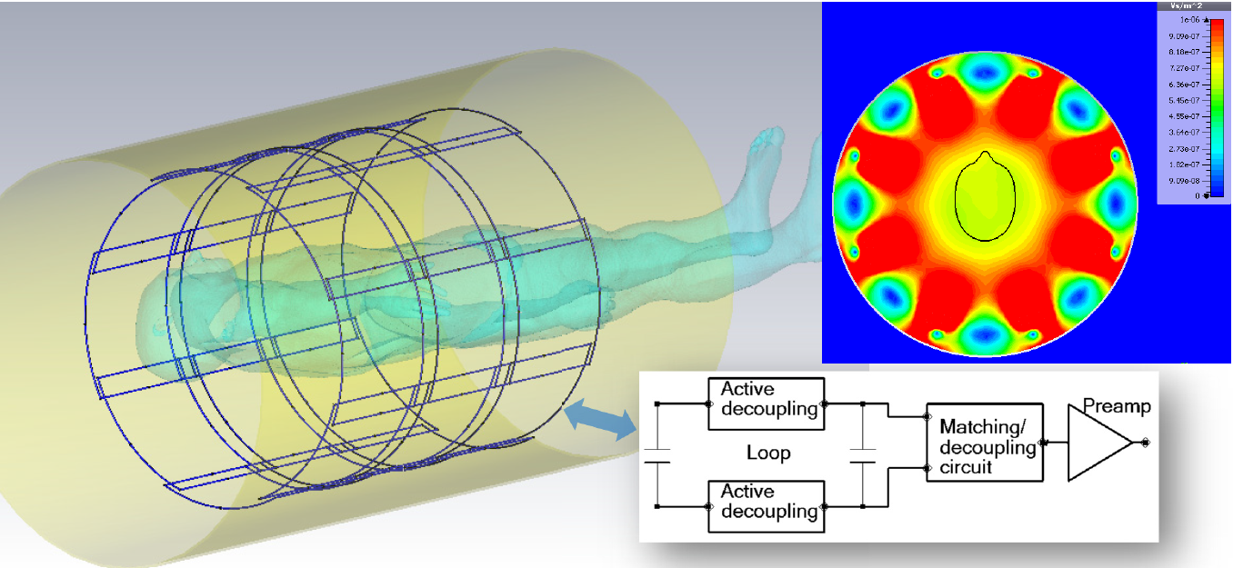
Fig. 1. Sketch of a wide bore receive array and a block diagram of each element. Simulated B1¯ normalized to 1W accepted power for one row of 8 elements.