1593
A Wireless Receive Surface Coil at 1.5T1Department of Radiology, University Medical Center Utrecht, Utrecht, Netherlands
Synopsis
Keywords: Non-Array RF Coils, Antennas & Waveguides, Non-Array RF Coils, Antennas & Waveguides, wireless coils, inductive coupling
Motivation: MRI is a highly preferable but also an expensive modality mainly due to 1)high operational cost, 2)staff cost, 3)long scan and preparation times.
Goal(s): Reducing costs and simplifying MRI scans.
Approach: A wired coil and a wireless coil which was inductively coupled to a receiver loop were compared in terms of their efficiency and SNR results.
Results: On the bench, a 0.8 dB+/-0.5dB of decrease was observed in the efficiency of the wireless coil over a range of 3 cm. The SNR of the wireless coil was practically identical to the wired coil both in phantom and in vivo MR images.
Impact: The efficiency obtained by a wired coil decreased by 0.8 dB when an inductively coupled wireless coil was used. Phantom and in vivo measurements show a practically identical sensitivity profile and SNR for both coils.
Introduction
MRI is a highly preferable but also an expensive modality mainly due to 1)high operational cost, 2)staff cost, 3)long scan and preparation times. Reducing costs and simplifying MRI scans are crucial for its sustainability. For more than 30 years, inductive matching has been proposed and implemented1,2. In fact, recent papers show that a single coil can be coupled to the body coil via inductive coupling3,4. However, such concept is limited to single channel only, which would lengthen the scan time compared to coil arrays. In this study, the applicability of the wireless reception of a surface coil was investigated by a small receiver loop coil that potentially could be extended to array setups.Methods
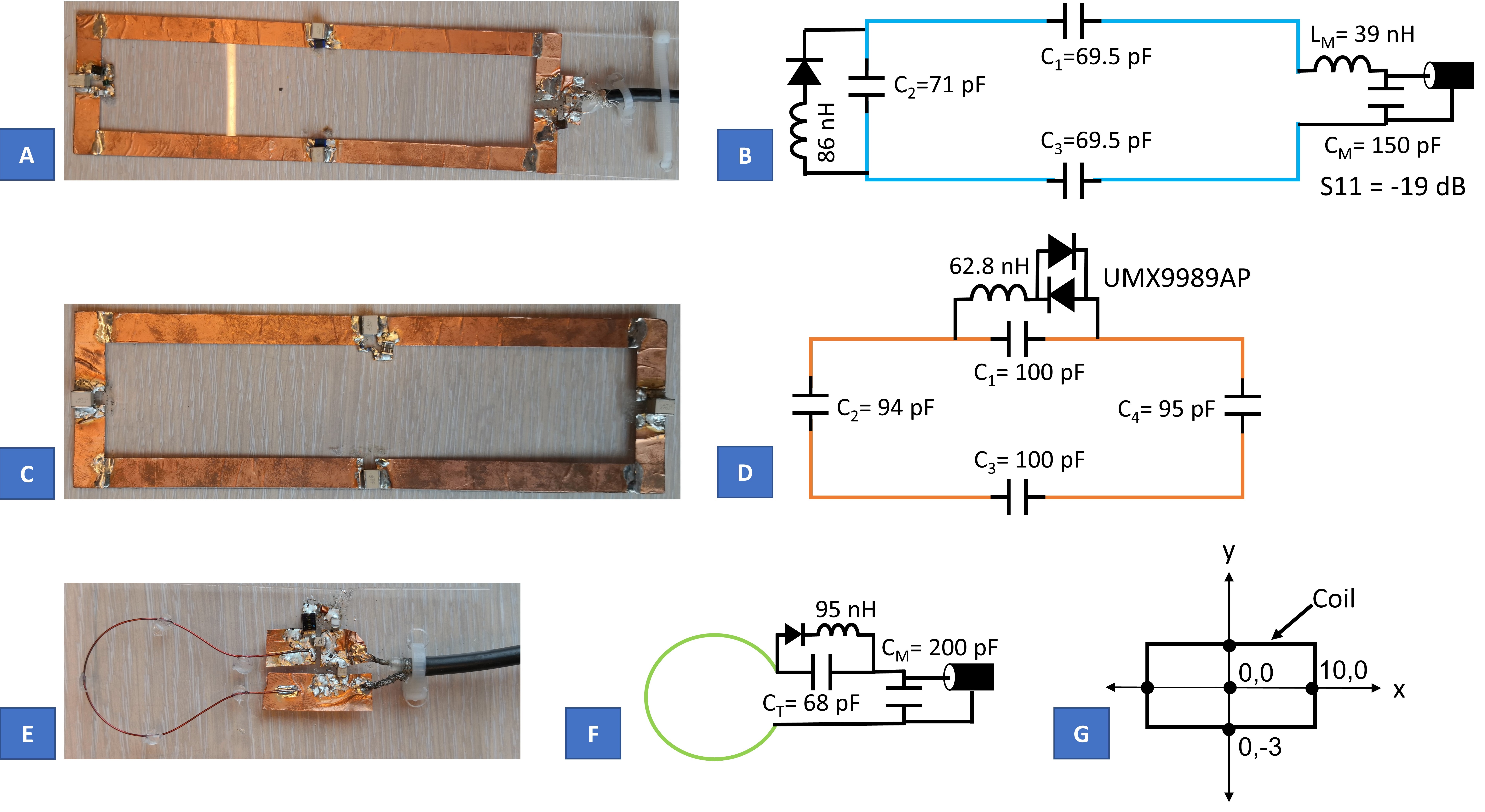
Coil DesignsA 6x20cm wired coil, namely, the reference coil, (Fig.1.A) was tuned and matched at 64MHz for a 1.5T system (Ingenia, Philips, Best, The Netherlands) when it was loaded with a body phantom (σ=0.32S/m, ε=45 at 100MHz). A detune circuit was applied (Fig.1.B) to decouple the coil from the transmit coil during RF-transmit.
A 6x20cm wireless coil (Fig.1.C) was tuned at 64 MHz when it was loaded with the body phantom. A passive detuning (UMX9989AP, Microsemi,California,USA) was applied (Fig.1.D).
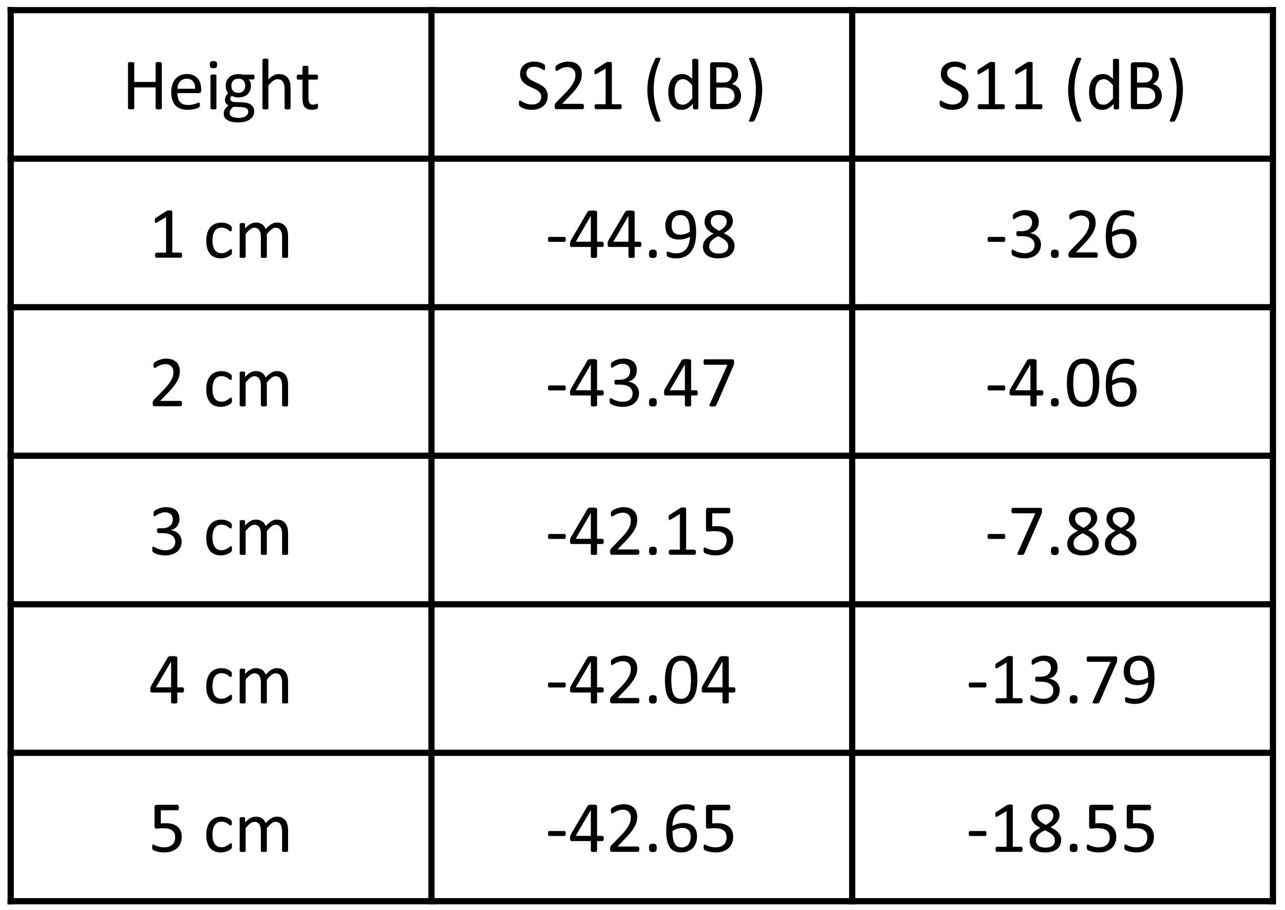
A loop coil of 3cm in diameter, namely, the receiver loop, (Fig.1.E) was tuned and matched at 64MHz when it was 5cm above the center of the loaded wireless coil. A detune circuit was applied (Fig.1.F). The reflection coefficient (S11) and S21 of the loop at different heights were measured.
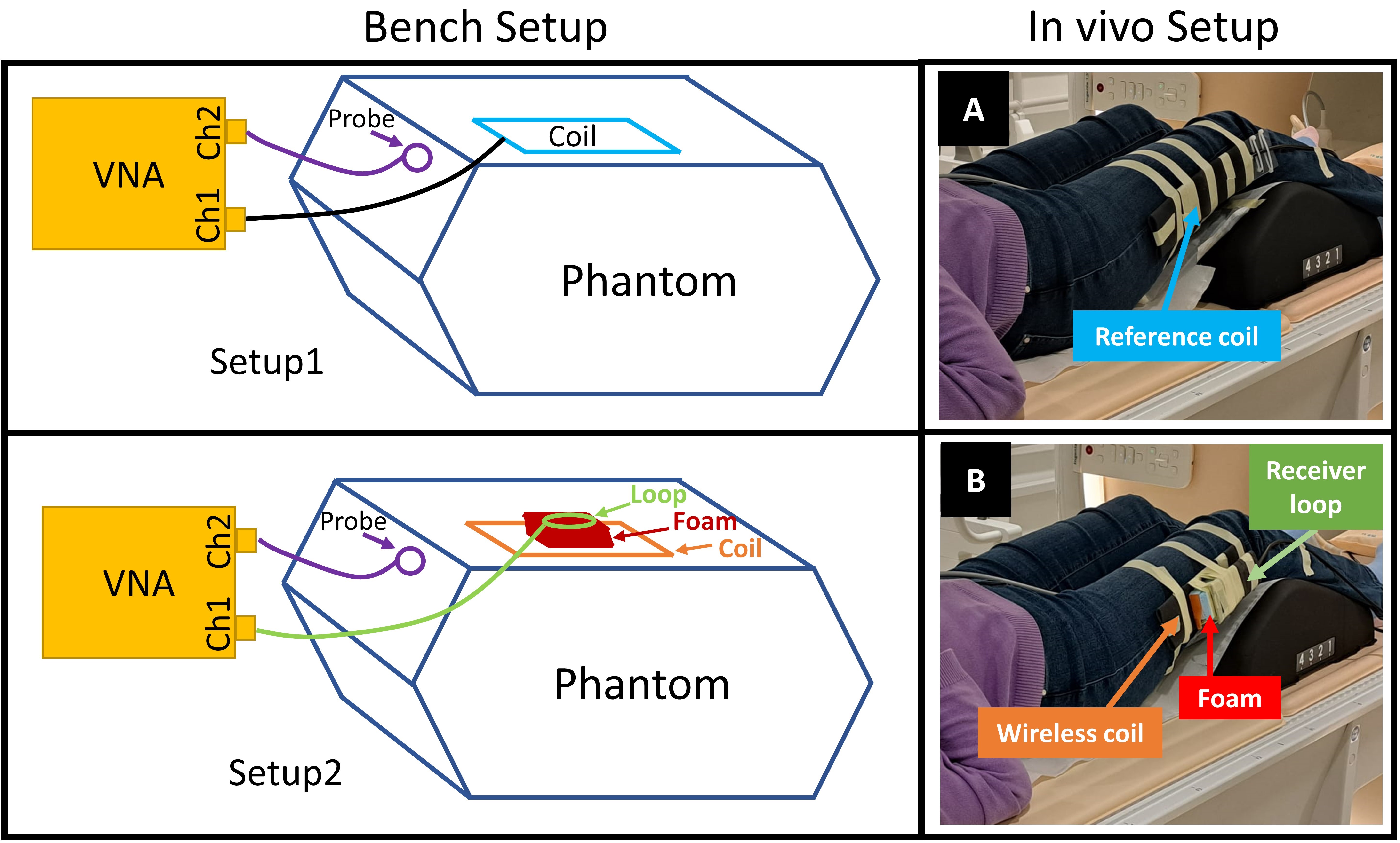
The efficiency of the reference coil and the wireless coil was measured as in Setup1 and Setup2 (Fig.2).
Phantom and In vivo Imaging
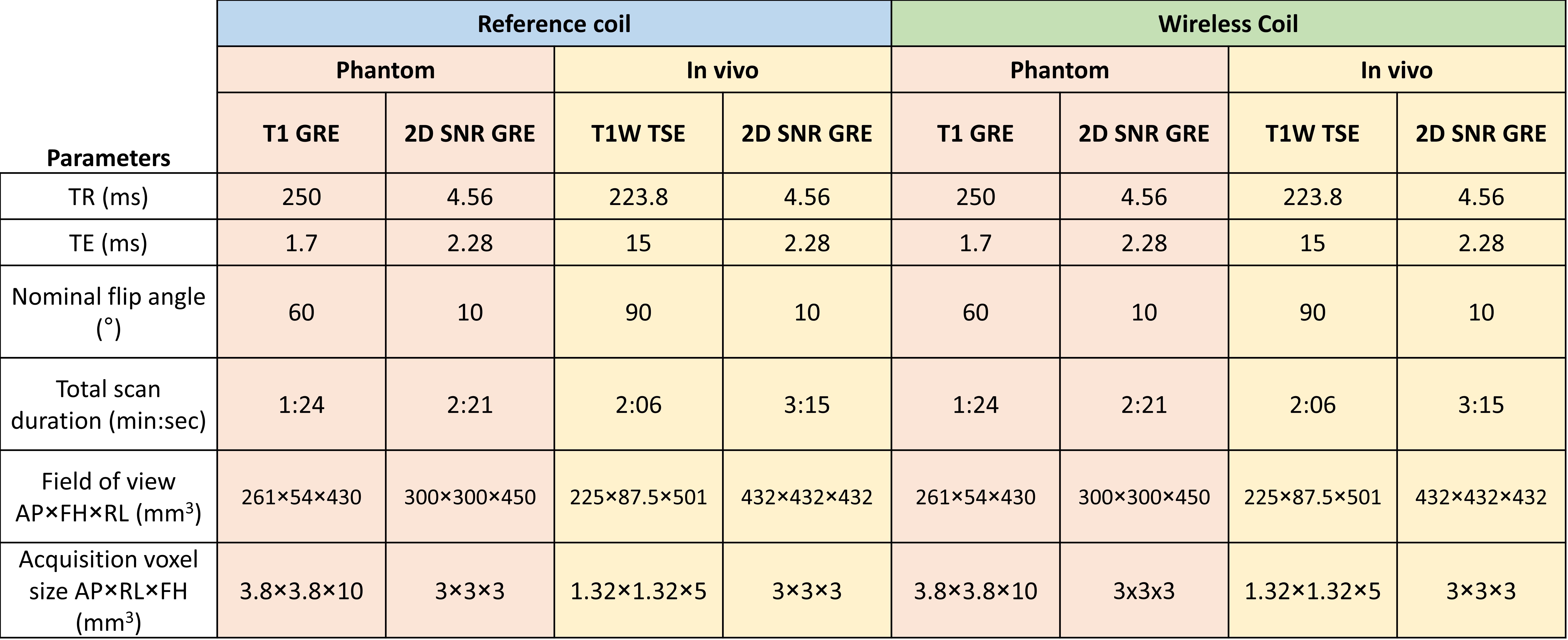
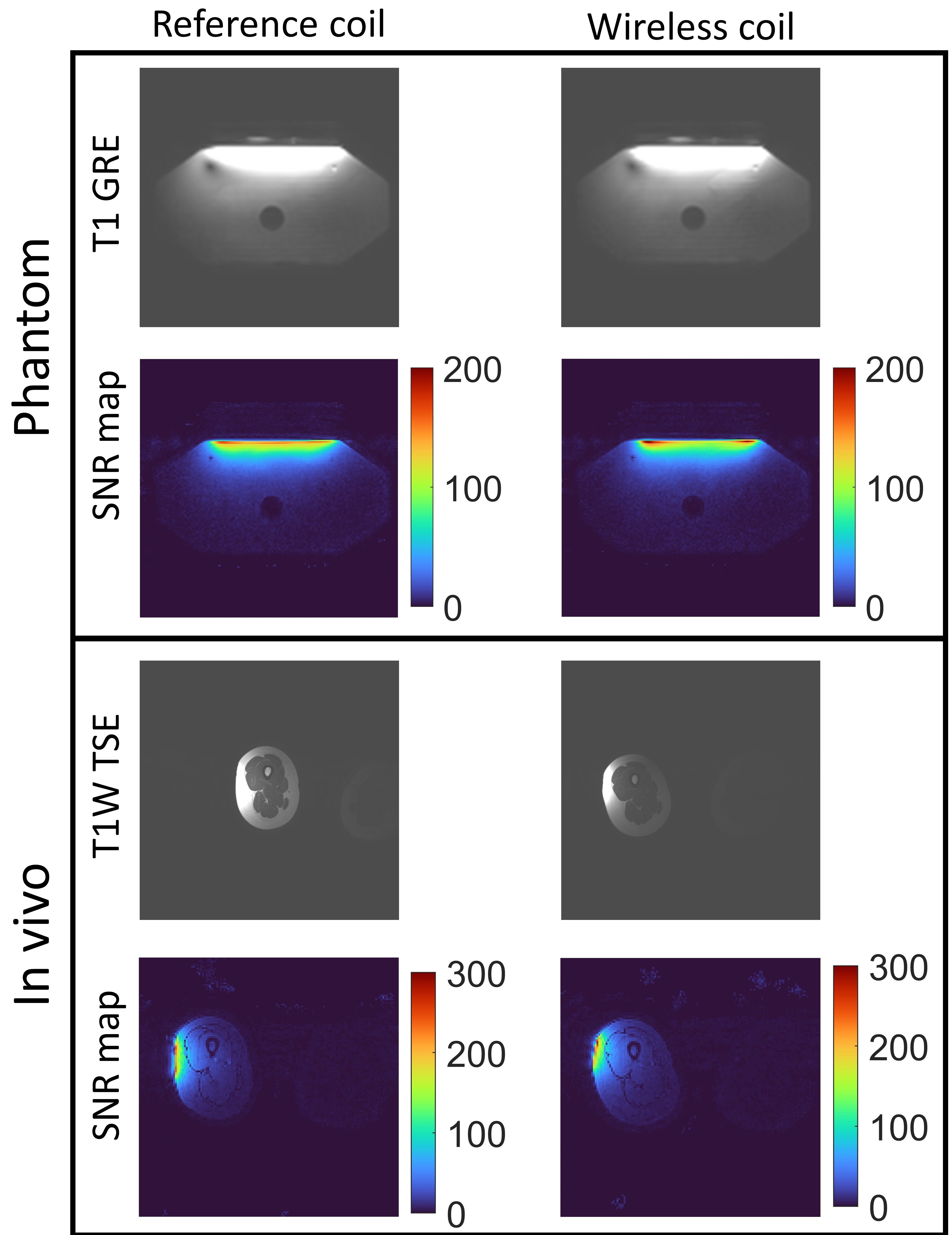
The reference coil was placed on the body phantom and directly connected to a receive interfacebox which includes the preamplifier. The wireless coil was placed on the same location of the body phantom. The receiver loop was placed 3cm above the wireless coil and only the loop was connected to the interface. T1-GRE and 2D-GRE-SNR sequences were acquired for the both coils (Fig.3).
The reference coil was placed on the side of the right upper leg of a healthy female volunteer (Fig.2A) and directly connected to the interface. The wireless coil was placed on the same location of the volunteer. The receiver loop was placed 3cm above the wireless coil and only the loop was connected to the interface (Fig.2B). T1-weighted-TSE and 2D-GRE-SNR sequences were acquired for both coils (Fig.3). The detuning of both coils was verified by acquiring B1 maps.
Results
Bench MeasurementsS21 of Setup1 and Setup2 was -40.34dB and -41.14dB, respectively. S21 when the receiver loop was placed at (10,0) and (0,-3) (Fig.1D) was -42.98dB and -43.25dB, respectively. S21 and S11 of the receiver loop at various distances are given in Fig.4. While S21 at 3, 4, and 5cm remained between -42.0dB and -42.65dB, that at 2cm and 1cm deteriorated 0.82dB and 2.33dB, respectively.
Phantom and In vivo Imaging
SNR maps of the reference coil and the wireless coil (Fig.5) were quite similar in terms of sensitivity profile, penetration depth, and SNR values. The maximum SNR of the reference coil and the wireless coil on the phantom was 166 and 195, respectively, and that in vivo was 248 and 273, respectively. The ability of the reference coil to receive signal from the left-hand side of the leg was better compared to the wireless coil.
Discussion
This work presented an implementation of the wireless reception of MR signal via inductive coupling. The bench results of Setup1 and Setup2 showed only a 0.8 dB decrease in the wireless reception, and the efficiency degraded by only 0.5dB over a range of 3cm in the wireless setup without altering the tuning and matching circuitry. Additionally, placing the receiver loop at the center yielded the best S21, and placing it at the edges of the coil substantially reduced the efficiency. Fig.4 pointed out that it is not the distance between the receiver loop and the target coil, but the matching of the receiver coil at that distance that affects the efficiency of the inductive coupling. Although S11 at 3cm of distance was not optimal, SNR at that distance was not affected owing to its high S21.In conclusion, this study demonstrated a simple wireless coil that within a range of 3cm remained at high sensitivity. Since the inductance coupled receiver is just 3cm in size, the setup would facilitate incorporating an array of wireless receivers that via for instance placing it under MR bed could be interfaced to the MRI system like a conventional wired array.
Acknowledgements
No acknowledgement found.References
1. Raad A, Darrasse L. Optimization of NMR receiver bandwidth by inductive coupling. Magn Reson Imaging. 1992;10(1). doi:10.1016/0730-725X(92)90373-8
2. Zhu H, Wang G, Petropoulos L. Multi-Element Wireless Stacked Phased Array Coil. In: Proc. Intl. Soc. Mag. Reson. Med. 20. ; 2012:2660-2660.
3. Lu M, Chai S, Zhu H, Yan X. Low‐cost inductively coupled stacked wireless RF coil for MRI at 3 T. NMR Biomed. 2023;36(1). doi:10.1002/nbm.4818
4. Okada T, Handa S, Ding B, et al. Insertable inductively coupled volumetric coils for MR microscopy in a human 7T MR system. Magn Reson Med. 2022;87(3):1613-1620. doi:10.1002/mrm.29062
Figures