1592
Studying Bandwidths of Balancing Preamplifier Decoupling Networks1Technical University of Denmark, Kongens Lyngby, Denmark
Synopsis
Keywords: RF Arrays & Systems, RF Arrays & Systems, matching networks, baluns, common-modes, noise matching, preamplifier decoupling
Motivation: Lattice baluns are traditionally used in receive arrays to achieve common mode rejection and preamplifier decoupling. They, however, are limited to real impedance transformations only.
Goal(s): New matching networks are sought that achieve noise matching and preamplifier decoupling, as well as common-mode rejection.
Approach: In this abstract, new network topologies are introduced and their bandwidths are studied.
Results: In addition to being more compact, the new networks offer a wider bandwidth as well as higher common-mode rejection. Thus, it is expected that the new networks are more resilient to component tolerances and loading effects, and they may enable multinuclear imaging.
Impact: New topologies of preamplifier decoupling networks with integrated balun functionality are introduced. They offer wider bandwidth and higher common-mode rejection compared to traditional networks.
Introduction
Baluns and cable traps are commonly used to reject common-mode currents to mitigate interference and improve SNR 1. Lumped-element baluns are often a preferable choice as other balun designs such as ferrite core and transmission line baluns are infeasible to use in an MR environment.In radio-frequency receive coil configurations, a separate balun stage can be used 2,3 in addition to a matching and decoupling network 4. Three-element networks that provide optimal noise matching and preamplifier decoupling have previously been found for receive coil arrays 5. Symmetric forms of these networks can also be used to maintain balance and provide a limited degree of common-mode rejection. Adding elements to matching and decoupling networks to allow for additional degrees of freedom was also previously investigated 6.
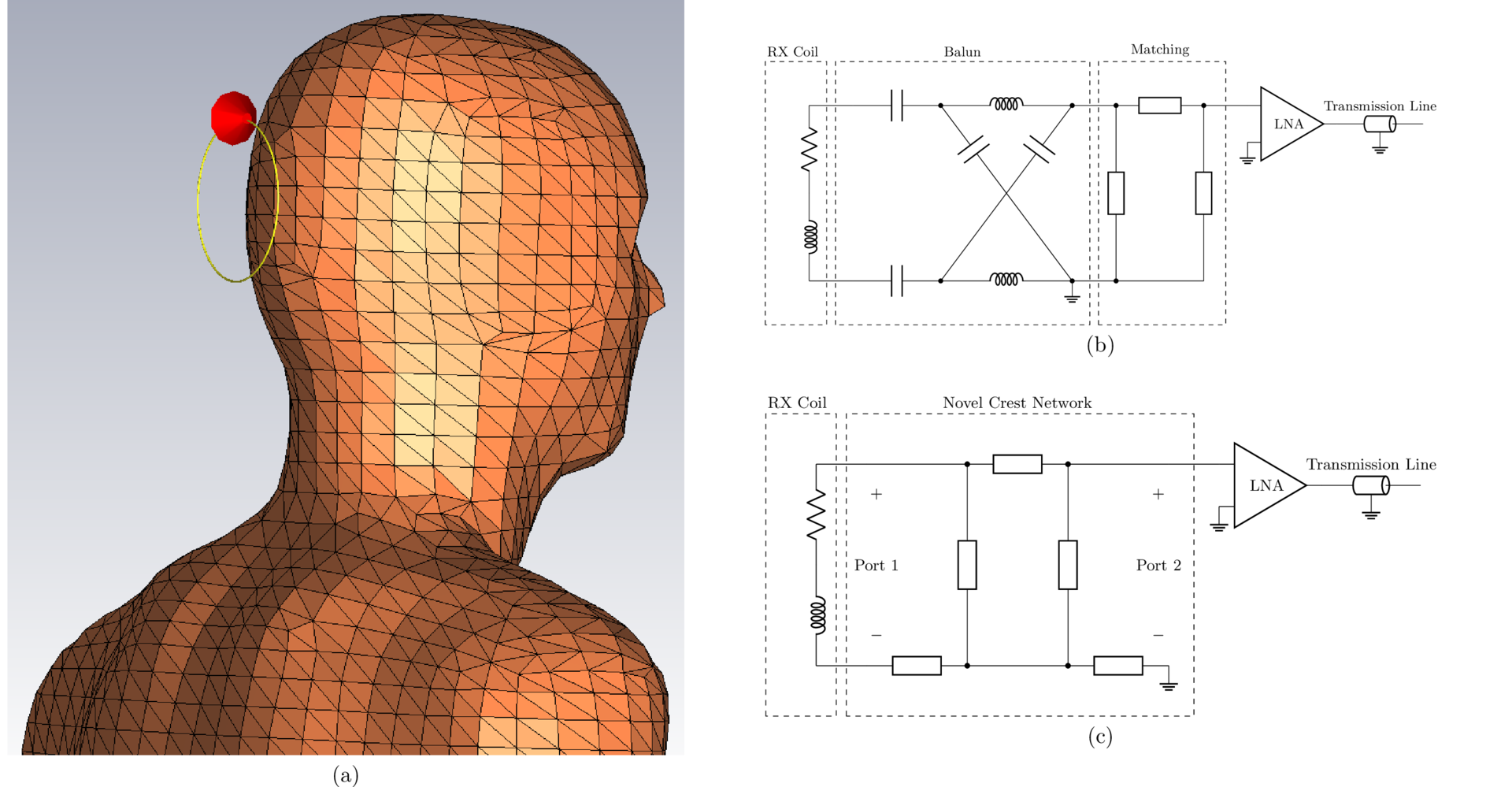
By adding elements to traditional network topologies, new five-element matching network topologies have been found that can provide not only optimal noise matching and preamplifier decoupling but also common-mode rejection. An example of a novel network and a traditional multistage design is illustrated in Figure 1. In addition to being more compact, the new matching networks can potentially offer wider bandwidth compared to traditional matching networks.
Methods
The noise figure and common-mode rejection ratio (CMRR) were evaluated for the proposed and traditional networks over a range of frequencies. Decoupling was not considered to evaluate bandwidths as it does not generally exhibit band-pass characteristics. Symmetrical equivalents of the networks from Wang et al.5 and a traditional multistage network with a separate balun stage were used for the benchmark. Each of the networks were determined for an example receive coil and preamplifier. The 3T proton Larmor frequency of 127.73 MHz was used as the operating frequency. The preamplifier used was the ElCry 2-u preamplifier7 since it is not pre-matched to 50Ω and thus can be used for wideband operation 8.CST was used to determine the behavior of the coil, this is shown in Figure 1a. The coil was an 8 cm diameter loop of 1 mm diameter copper wire. The coil was positioned approximately 15 mm from the posterior of a head phantom. The phantom geometry used was the Virtual Family Duke v2 9,10 The electrical properties of the phantom were $$$ε_r = 60.97$$$ and $$$σ = 0.440$$$ S m-1 to emulate a human brain 11. One-port parameters of the coil were exported as a Touchstone file for use with a circuit simulator.
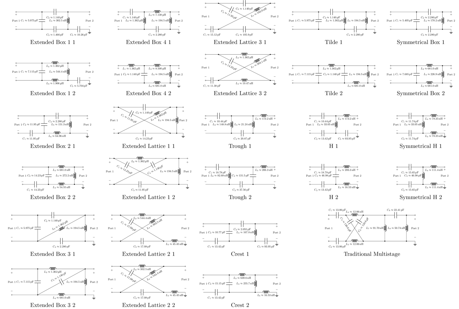
The coil impedance was $$$Z_{coil}=1.875+190.788jΩ$$$ at the design frequency. Networks were designed for an amplifier input impedance of $$$Z_{amp}=45.474−135.560jΩ$$$, an amplifier optimal noise impedance of $$$Z_{n,opt}=45.740+29.525jΩ$$$, and the simulated coil impedance at the design frequency 7. Figure 2 presents these networks.
Design examples were simulated in Keysight Advanced Design System (ADS) to determine their CMRRs and noise figures. Precise component values from the design equations were used in simulations to compare networks under the same conditions regardless of component tolerances and non-ideal effects. Bandwidths were determined as the range of frequencies that provided at least 100 dB of CMRR and noise figures of at most 1 dB.
Results
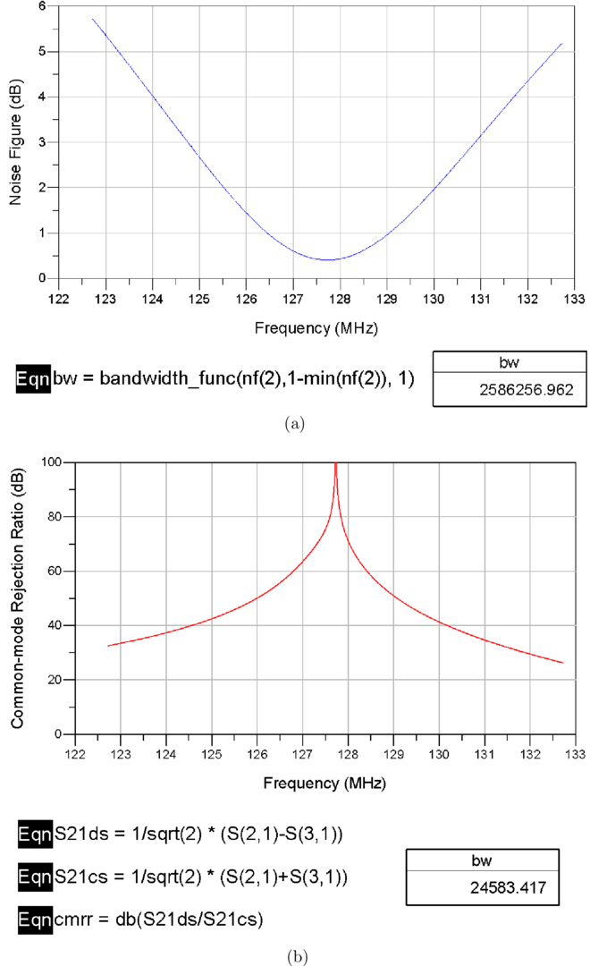
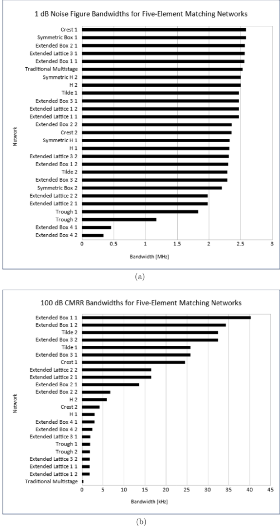
Figure 3 presents the results from the ADS simulations for an example network. The results for all of the networks are summarized in Figure 4. The symmetric matching networks were not included in Figure 4b as their maximum CMRRs were below the 100 dB threshold.Discussion
The crest solution 1 network has the greatest noise figure bandwidth of all networks considered. The traditional network with the greatest noise figure bandwidth is the symmetric box solution 1 network, which concurs with Wang et al.5 that the Π-1 solution has the greatest bandwidth. The extended box 1 solution 1 network has the greatest CMRR bandwidth. CMRR bandwidths were significantly smaller compared to noise figure bandwidths, though some topologies have CMRRs that plateau with respect to frequency, as Figure 3b shows.Conclusion
Bandwidths of new and traditional matching networks in terms of noise figure and CMRR have been compared. The crest solution 1 network has the potential to provide low noise figure over a greater bandwidth compared to traditional symmetric matching networks in addition to providing greater common-mode rejection.It is anticipated that the new matching networks will reduce requirements for cable traps and separate balun stages for common-mode rejection. Greater usable bandwidth also implies that the networks will be more robust to component tolerances and loading effects. This may also enable the new matching networks to be used for multinuclear imaging for nuclei with close Larmor frequencies.
Acknowledgements
No acknowledgement found.References
1. Peterson D M. Impedance Matching and Baluns. John Wiley & Sons, Ltd; 2011.
2. Malik N, Clark M, Juhasz K, Eigenbrodt E, Stormont R, Lindsay S, inventors; General Electric Company, assignee. An Anterior Radio Frequency (RF) Coil Array for a Magnetic Resonance Imaging (MRI) System. US Patent 10921401-B2. February 16, 2021.
3. Fuqua H, Taracila V, Giancola M, Stormont R, inventors; General Electric Company, assignee. Conforming Posterior Radio Frequency (RF) Coil Array for a Magnetic Resonance Imaging (MRI) System. US Patent 11402447-B2. August 2, 2021.
4. Roemer P B, Edelstein W A, Hayes C E, Souza S P, Mueller O M. The NMR phased array. Magnetic Resonance in Medicine. 1990;16(2):192-225.
5. Wang W, Zhurbenko V, Sanchez-Heredia J D, Ardenkjær-Larsen J H. Three-element matching networks for receive-only MRI coil decoupling. Magnetic Resonance in Medicine. 2021;85(1):544-550.2
6. Reykowski A, Wright S M., Porter J R.. Design of Matching Networks for Low Noise Preamplifiers. Magnetic Resonance in Medicine. 1995;33(6):848-852.
7. ElCry. Ultra-Wideband Low-Noise Preamplifier elcry2-u.2022. http://elcry.com/vz/elcry2-u.pdf. Accessed July 21, 2023.
8. Sun C, Bauer C C, Hou J, Wright S M. Wideband receive-coil array design using high-impedance amplifiers for broadband decoupling. Magnetic Resonance in Medicine. 2023;90(5):2198-2210.
9. Andreasen H K. Design and Implementation of an 8-channel Array for High Field MRI. Bachelor’s thesis. DTU Electromagnetic Systems, Department of Electrical Engineering. DTU, Department of Electrical Engineering, Ørsteds Plads, Building 348, 2800 Kgs. Lyngby Denmark. 2021.
10. Gosselin M, Neufeld E, Moser H, et al. Development of a new generation of high-resolution anatomical models for medical device evaluation: the Virtual Population 3.0. Physics in Medicine & Biology.2014;59(18):5287.
11. Gabriel C, Gabriel S. Compilation of the Dielectric Properties of Body Tissues at RF and Microwave Frequencies http://www.dtic.mil/dtic/tr/fulltext/u2/a305826.pdf.Accessed: 2023-07-21 from http://niremf.ifac.cnr.it/docs/DIELECTRIC/home.html and http://niremf.ifac.cnr.it/tissprop/htmlclie/htmlclie.php; 1996.
12. Bockelman D E, Eisenstadt W R. Combined differential and common-mode analysis of power splitters and combiners. IEEE Transactions on Microwave Theory and Techniques. 1995;43(11):2627-2632.
Figures