1590
Simulation Setup for Demonstrating SNR Performance of Preamplifier Decoupled versus Power Matched Receive Coils1Technical University of Denmark, Kongens Lyngby, Denmark
Synopsis
Keywords: RF Arrays & Systems, RF Arrays & Systems, preamplifiers, preamplifier decoupling, power matching, noise matching, matching networks
Motivation: While preamplifier decoupling is a widely accepted technique, based on impedance mismatching, it appears counter-intuitive and still introduces confusion in the MRI community and scientists, who are not electrical engineers by training.
Goal(s): This work aims to develop a simulation setup, which clearly illustrates the signal-to-noise ratio (SNR) in preamplifier decoupled and power matched receive coils.
Approach: Circuit simulations are used to compare SNR at the output of power matched and preamplifier decoupled coils in 3T MRI systems.
Results: The networks yield similar SNR, despite having significantly different input reflection coefficients; demonstrating that preamplifier decoupling and power matching approaches lead to equivalent SNR.
Impact: The developed demonstrator is useful in understanding properties of preamplifier decoupling and breaking down a range of associated misconceptions. This can facilitate mastering a proper use of this decoupling method.
Introduction
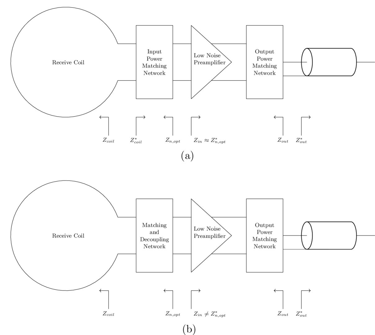
Radio-frequency receive coil array elements can couple with each other due to mutual inductance, which results in coil detuning. Preamplifier decoupling is a method used to mitigate these interactions by ensuring that the input impedance presented to a receive coil element results in reflections, which minimize the current in the receive coil 1. Input matching networks can ensure that the optimal source impedance is presented to the preamplifier input for minimal noise, while also maintaining optimal preamplifier decoupling 2,3,4 . Impedance matching for maximum power transfer is also used for receive coil configurations where preamplifier decoupling is not needed.Figure 1 presents block diagrams of receive coil networks with conventional power matching and preamplifier decoupling. Figure 1a uses a preamplifier with an input impedance of $$$Z_{in}≈Z_{n,opt}^{*}$$$, such that it can be simultaneously noise and power matched, where $$$Z_{n,opt}$$$ is its optimal source impedance for minimal noise. The network in Figure 1b has $$$Z_{in}≠Z_{n,opt}^{*}$$$ , which allows for reflections, to enable preamplifier decoupling. In both networks, an output matching network is used to ensure that the preamplifier is impedance matched with the transmission line that it is connected to.
Despite preamplifier decoupling resulting in sub-optimal power matching, equivalent signal-to-noise ratio (SNR) can be achieved with both of these configurations due to noise matching 5. This theoretical result may seem counter-intuitive, hence this work aims to elucidate this through simulations of receive coil feed circuits.
Methods
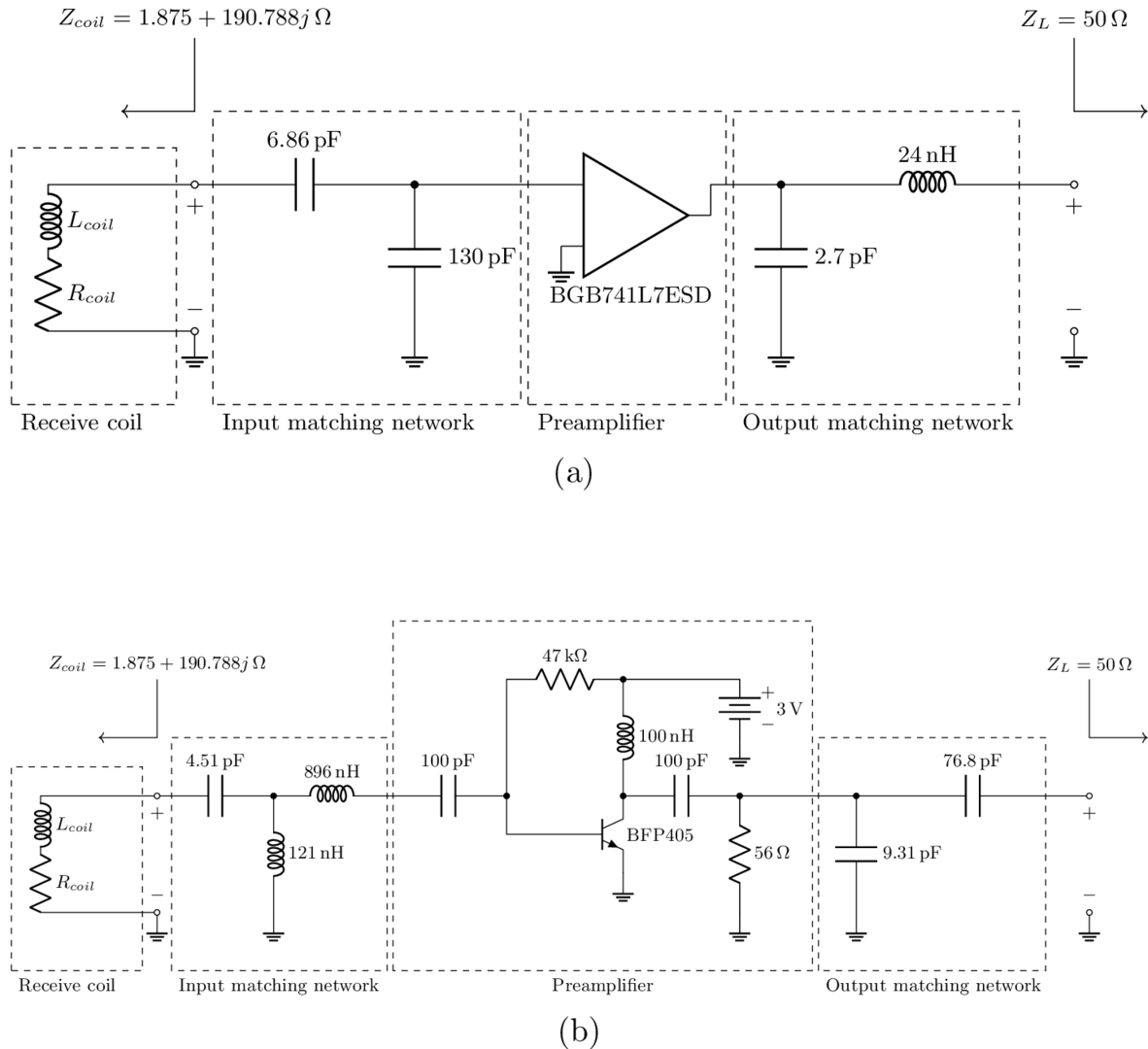
Two receive coil networks were simulated to compare the SNR from power matching and preamplifier decoupling. These networks were designed for a receive coil operating at the $$$3\text{T}$$$ proton Larmor frequency of $$$127.73\text{MHz}$$$. The simple loop coil with a diameter of $$$8\text{cm}$$$ of $$$1\text{mm}$$$ copper wire placed approximately $$$15\text{mm}$$$ from a head model was EM simulated and has an impedance of $$$Z_{coil}=1.875+190.788jΩ$$$.Figure 2 shows circuit diagrams for each coil interfacing network. The networks have input matching circuits that transform the coil impedance to the optimal source impedances for the preamplifiers for minimal noise. For the first network, this also results in power matching. The input matching network for the second network uses the concept described by Roemer et al.1 and a circuit topology from Wang et al.3 to present maximum input impedance to the coil for decoupling. Both networks have an output matching network, which matches the amplifier output impedance to a $$$50Ω$$$ transmission line.
The first network uses an Infineon BGB741L7ESD amplifier6, whereas the second network uses an amplifier with an Infineon BFP405 transistor7. The minimum noise figure at the design frequency is $$$0.966\text{dB}$$$ for the first network and $$$1.082\text{dB}$$$ for the second network. Given that both amplifiers have similar minimum noise figures and are noise matched at their inputs, the SNR at their outputs is expected to be similar.
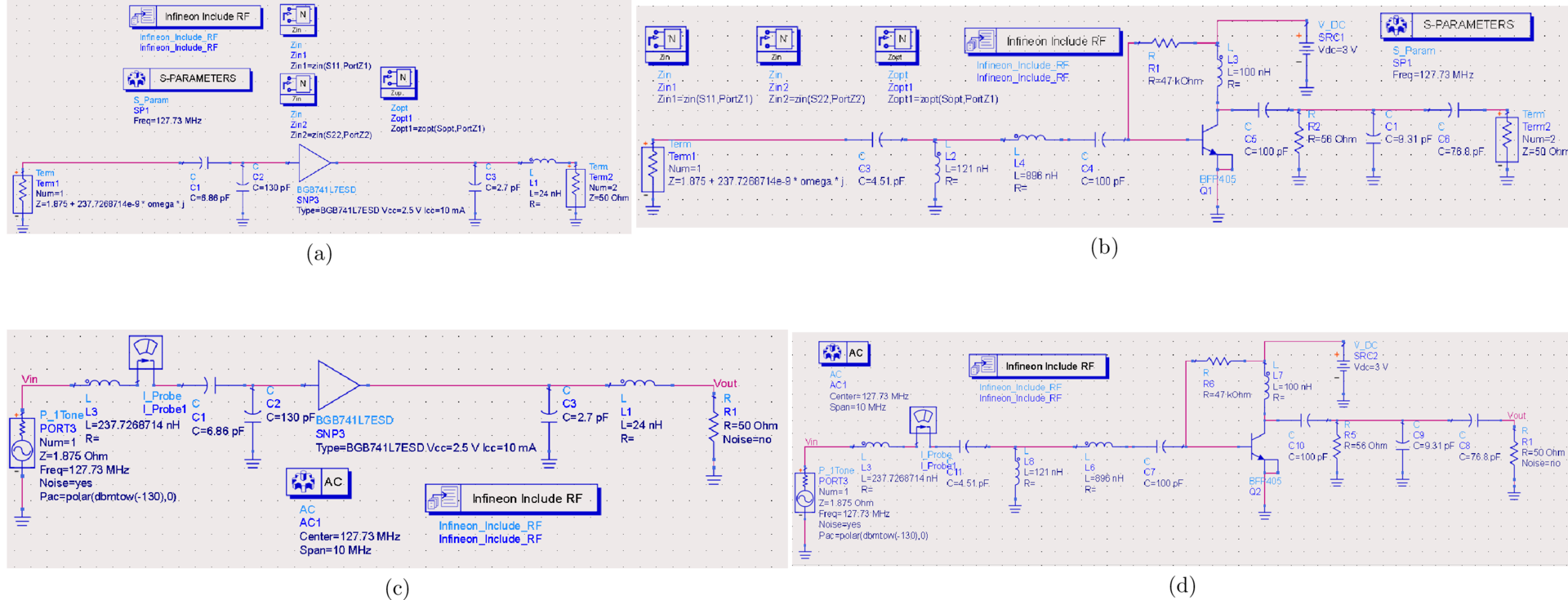
Keysight Advanced Design System (ADS) was used to simulate the networks with the schematics presented in Figure 3 8. S-parameter simulations were employed to gauge the reflection coefficients and gains of the networks. AC simulations used a $$$−130\text{dBm}$$$ power source at the coil to emulate a received MR signal. The SNR at the transmission line due to this excitation was then calculated using the following formula:
$$SNR_{dB}=20\log_{10}\left(\frac{V_{out}}{V_{n,out}}\right)$$
$$$V_{out}$$$ and $$$V_{n,out}$$$ denote the root-mean-squared (RMS) voltages for the signal and noise at the output.
Results
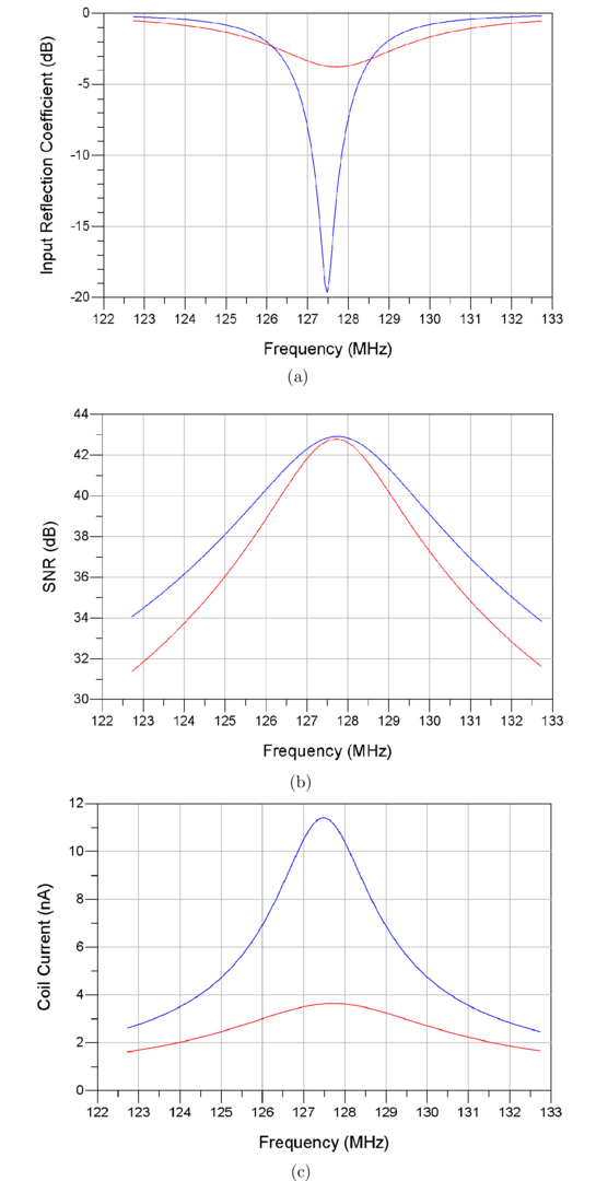
The results from the circuit simulations are displayed in Figure 4. Frequency sweeps of the power wave reflection coefficients, SNR, and coil current magnitude are presented for both configurations.Discussion
Figure 4 indicates that despite the significant discrepancy in input reflection coefficient, both networks yield similar SNR at the design frequency. The results also demonstrate that the preamplifier decoupled network has significantly reduced coil current, which provides decoupling. The small difference in SNR of $$$0.115\text{dB}$$$ between the two networks is attributed to the different noise figure for the two preamplifiers, of $$$1.082\text{dB}−0.966\text{dB}≈0.116\text{dB}$$$. This demonstrates that despite preamplifier decoupling adding reflections at the input, the noise figure can be preserved through noise matching, resulting in similar SNR.Conclusion
The SNR acquired from receive coils with preamplifier decoupling and power matching were compared. Both networks yielded nearly identical SNR, demonstrating that preamplifier decoupling is able to provide low noise, while mitigating coil detuning due to coupling between receive coil array elements.Decoupling is a vital concept in receive coil array development to ensure that image quality is not degraded due to interference. Preamplifier decoupling is versatile as it does not require restrictions on coil geometry and does not reduce SNR. Further research involving preamplifier decoupling includes implementing decoupling for multinuclear coils and alleviating loading tolerance effects on decoupling.
Acknowledgements
No acknowledgement found.References
1. Roemer P B, Edelstein W A, Hayes C E, Souza S P, Mueller O M. The NMR phased array. Magnetic Resonance in Medicine. 1990;16(2):192-225.
2. Reykowski A, Wright S M., Porter J R.. Design of Matching Networks for Low Noise Preamplifiers. Magnetic Resonance in Medicine. 1995;33(6):848-852.
3. Wang W, Zhurbenko V, Sanchez-Heredia J D, Ardenkjær-Larsen J H. Three-element matching networks for receive-only MRI coil decoupling. Magnetic Resonance in Medicine. 2021;85(1):544-550.
4. Wang W, Zhurbenko V, Sanchez-Heredia J D, Ardenkjær-Larsen J H. Trade-off between preamplifier noise figure and decoupling in MRI detectors. Magnetic Resonance in Medicine. 2023;89(2):859-871.
5. Webb A. Magnetic Resonance Technology: Hardware and System Component Design.ch. 3, :118-120. Thomas Graham House, Science Park, Milton Road, Cambridge CB4 0WF, UK: Royal Society of Chemistry 2016.
6. Infineon Technologies AG . BGB741L7ESD https://www.infineon.com/cms/en/product/rf/low-noise-amplifier-lna-ics/multi-purpose-lnas/bgb741l7esd/. Accessed: 2023-10-31; 2018.
7. Infineon Technologies AG . BFP405 https://www.infineon.com/cms/en/product/rf/rf-transistor/low-noise-rf-transistors/bfp405/. Accessed: 2023-10-31; 2016
8. Jepsen R A, Ardenkjær-Larsen J H, Zhurbenko V. Circuit Simulations for Demonstrating SNR Performance of Preamplifier Decoupled versus Power Matched Receive Coils. https://doi.org/10.5281/zenodo.10079061 . 2023.
Figures