1585
A 2-ch Wearable Elastic Adjustable Retunable (WEAR) Surface Coil at 3T with Broadband Matching1Department of Radiology, University Medical Center Utrecht, Utrecht, Netherlands, 2R&D Division, ETL Systems, Rickmansworth, United Kingdom, 3The Institute of Biomedical Enginnering, Bogazici University, Istanbul, Turkey
Synopsis
Keywords: New Devices, New Devices, flexible coils, broadband matching, elastic coils, textile coils, stretchable coils
Motivation: Fixed-volume copper coils fail to accommodate volume changes and flexing of the imaging region, therefore spoil MR signal and hamper the diagnosis.
Goal(s): To design a flexible surface coil for breast MR imaging.
Approach: A 2-ch stretchable knitted textile coil and a 2-ch reference copper coil, which were compatible with three different sized phantoms were compared in terms of their sensitivity profiles and SNR results.
Results: A three-stage broadband matching network could compensate for 15MHz of frequency shift. Although the textile coil was 31-81% more lossy compared to the copper coil, it only resulted in 10-26% SNR decrease.
Impact: Despite loss of the WEAR coil, a textile-based coil can sustain a sample-loss-dominated behavior and a broadband matching network can compensate for the frequency shift without compromising on SNR.
Introduction
Conformal and flexible coils can enable fast and simplified MR acquisitions, thus, reducing scan costs and providing patient comfort. Recent studies1–3 have demonstrated the applicability of stretchable coils in MRI. However, compensation for the frequency shift due to stretching or in the case of different loadings of copper coils still remains a challenge. This study introduces a knitted textile coil and compares it to a reference coil. A broadband-matching method4 is proposed to compensate for the frequency shift.Methods
The 2-ch Wearable Elastic Adjustable Retunable (WEAR) CoilA highly conductive silver thread (Statex, Germany) with linear resistivity of 30 W/m was knitted in a knitted machine (NSSG-122,Shima Seiki,Japan) with an elastofiber. The knitted textile had 115% of elasticity when horizontally stretched. To create each channel, three pieces of textile, 80 mm, 80 mm, and 100 mm were united via three connection circuits (Fig.1.a,b). Three phantoms, S(627 mL), M(785mL), and L(986 mL), were filled with a solution (2.5g/L NaCl, 0.5g/L CuSO4.5H2O, σ=0.56 S/m). Each channel was tuned on the M phantom at 127.7MHz for a 3T system (Ingenia-CX, Philips, Best, The Netherlands). A single-stage matching was applied to calculate Qunloaded and Qloaded by 3dB bandwidth of S11. The loss of the WEAR coil was calculated according to R=ωL/Q. A detune circuit was applied (Fig.2.a) and decoupling between the channels was satisfied via overlapping (Fig.1.a,c). The frequency shift occurring when the coil was on the S and the L phantom was recorded. Three-stage broadband-matching (Fig.2.c) was applied to compensate for the frequency shift range.
The 2-ch Reference Coil
A copper coil (Fig.1.c) having the same geometry as the WEAR coil was designed. Each channel was tuned on the M phantom at 127.7MHz. A single-stage matching was applied to calculate Qunloaded and Qloaded by 3dB bandwidth of S11. A detune circuit was used (Fig.2.b) and the decoupling between the channels was achieved as in Fig.1.d. The frequency shift occurring when the coil was loaded with the S and the L phantom was recorded. Two-stage broadband matching was applied (Fig.2.c).
Phantom Studies
The WEAR coil and the reference coil were loaded with the S, the M, and the L phantom respectively. No further tuning was applied when their broadband-matching circuits were connected. T1-weighted TSE protocol (FOV:160x160x60mm3, TE/TR= 8/461ms, voxel size=1x1.25x3mm3, flip angle=90°) was applied.
Results
Bench MeasurementsThe inductance of the WEAR coil on the S, the M, and the L were 300nH, 365nH, and 470nH, respectively. The inductance of the reference coil was 310nH. Qunloaded of the WEAR coil increased as the coil underwent more stretching, which, in turn, increased its dimensions (Fig.3). The loss of the WEAR coil on the S, the M, and the L phantom was 0.5Ω, 0.55Ω, and 0.69Ω, respectively. The loss of the reference coil was 0.38Ω. The frequency shift occurring when the WEAR coil was on the S and the L phantom was 8MHz and 7MHz, respectively. The frequency shift observed when the reference coil was on the S and the L phantom was 1MHz and 2MHz, respectively (Fig.4). the three-stage and two-stage broadband-matching circuit could compensate for 15 MHz and 3 MHz of frequency shift, respectively. Decoupling between the channels were below -10dB for both coils.
Phantom Studies
The sensitivity profile of the reference coil and the WEAR coil was similar such that the signal intensity was high at the center of the phantom and low at the top edges (Fig.5). SNR decrease in the circular areas of the WEAR coil images was 26%, 10%, and 13.5% for the S, the M, and the L phantom, respectively, compared to the reference coil images.
Discussion
This work proposed a broadband matching network to compensate for the frequency shift occurring because of either stretching elastic coils or different loadings of conventional copper coils. Increasing the number of stages from two to three widened the bandwidth 5-fold. It is observed that SNR decreases as the volume of the phantom increases, simply because the magnetic field strength decreases with the cube of the distance from the center of the coil. Although the loss of the WEAR coil on the S, the M, and the L phantom increased 31.6%, 44.7%, and 81.6%, respectively compared to that of the reference coil, the corresponding SNR decrease remained between 10-26%. This fact indicates that despite the high loss of the WEAR coil and using more than one matching stage, a textile-based coil can sustain a sample-loss-dominated behavior. The broadband-matched WEAR coil can potentially mitigate fitting or underloading problems in breast MRI.Acknowledgements
No acknowledgement found.References
1. Vincent JM, Rispoli J V. Conductive Thread-Based Stretchable and Flexible Radiofrequency Coils for Magnetic Resonance Imaging. IEEE Trans Biomed Eng. 2020;67(8). doi:10.1109/TBME.2019.2956682
2. Motovilova E, Tan ET, Taracila V, et al. Stretchable self-tuning MRI receive coils based on liquid metal technology (LiquiTune). Sci Rep. 2021;11(1). doi:10.1038/s41598-021-95335-6
3. Port A, Luechinger R, Albisetti L, et al. Detector clothes for MRI: A wearable array receiver based on liquid metal in elastic tubes. Sci Rep. 2020;10(1). doi:10.1038/s41598-020-65634-5
4. Yegin K, Martin AQ. On the design of broad-band loaded wire antennas using the simplified real frequency technique and a genetic algorithm. IEEE Trans Antennas Propag. 2003;51(2). doi:10.1109/TAP.2003.809056
Figures
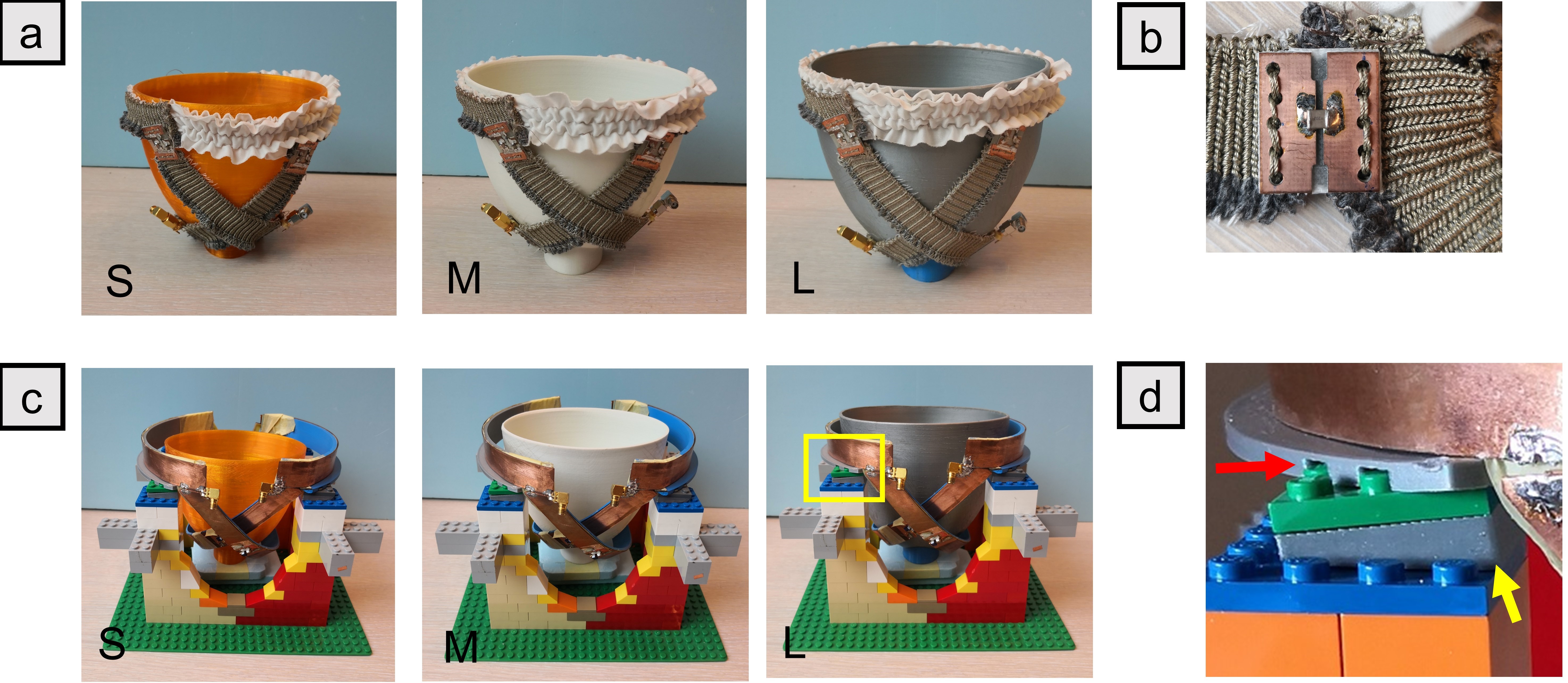
Figure 1: a: The placement of the WEAR coil on the S, the M, and the L phantom. b:The connection circuits used for soldering lump elements. c: The reference coil loaded with the S, the M, and the L phantom. d: The enlarged view of the yellow frame in (c) to show the custom-made piece to satisfy decoupling between the channels.
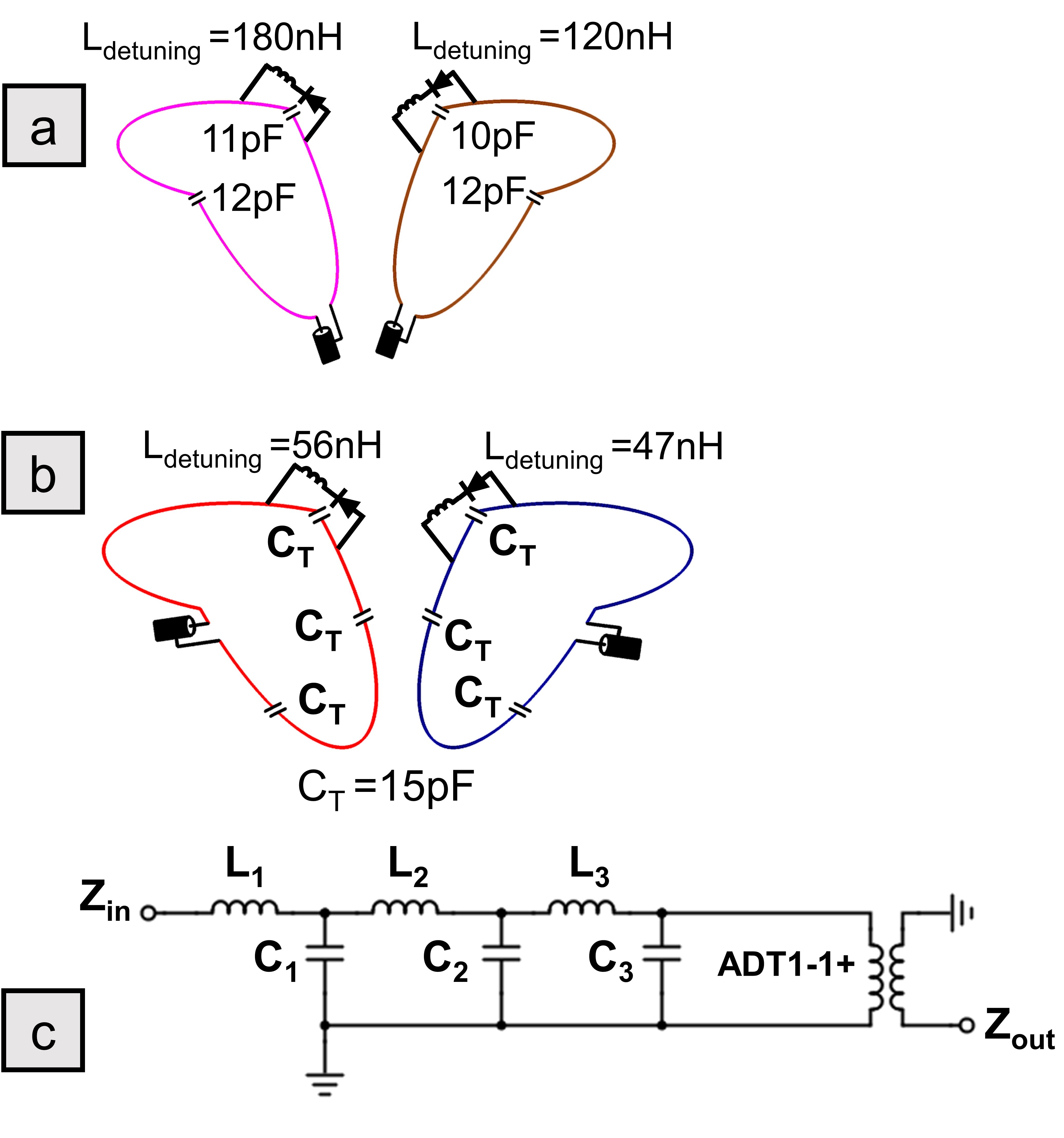
Figure 2: The schematic of (a) the WEAR coil, (b) the reference coil, and (c) the three-stage matching circuit where each LC pair indicates a stage and ADT1-1+ (Mini-Circuits, USA) was used as balun. L1, C1, L2, C2, L3, and C3 used for the matching of the WEAR coil were 22 nH, 130-160 pF tunable, 47 nH, 60-80 pF tunable, 100 nH, 30-40 pF tunable, respectively. L1, C1, L2, and C2 used for the matching of the reference coil were 47 nH, 40-70pF tunable, 47 nH, and 40-70pF tunable, respectively.
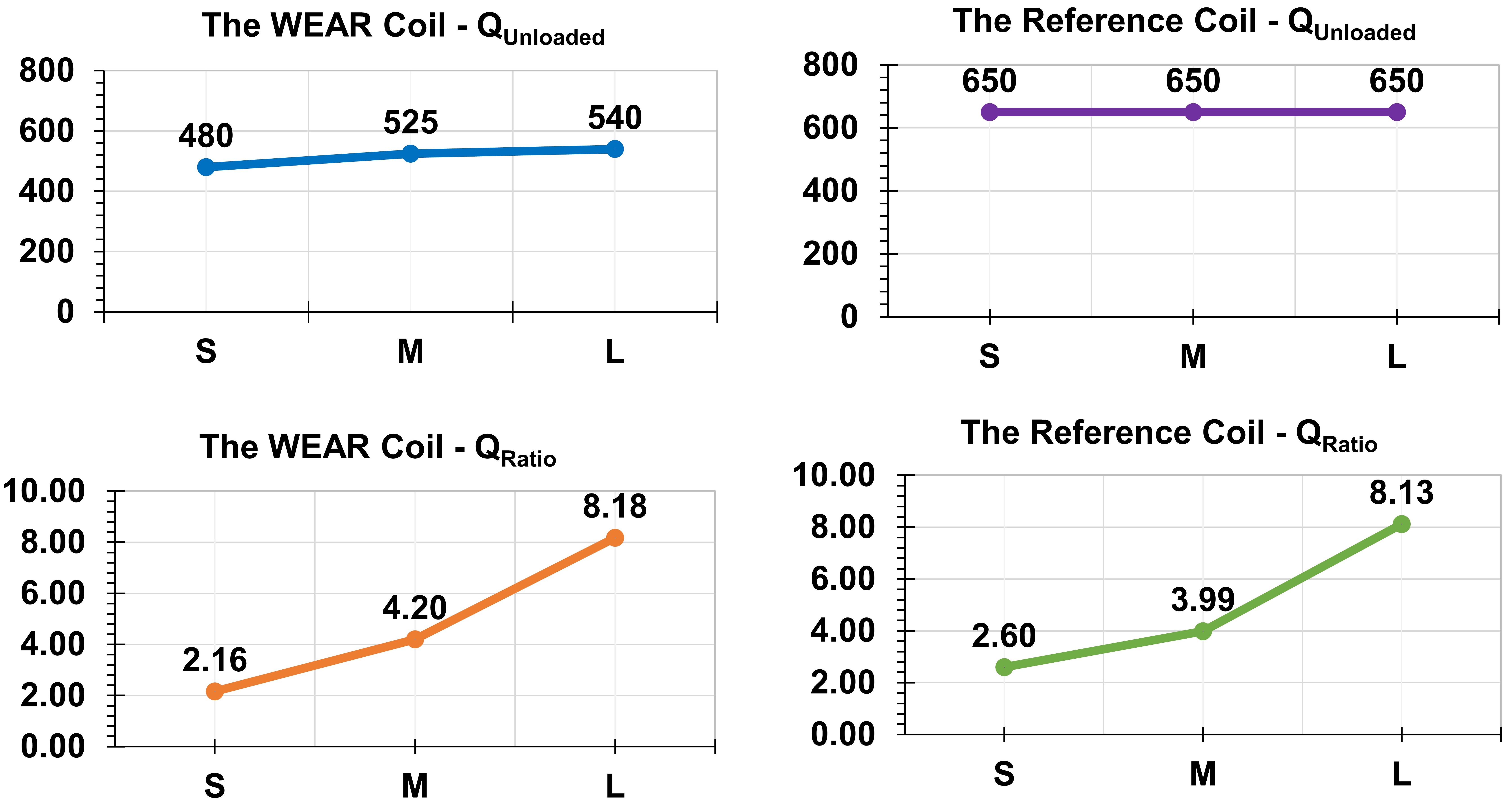
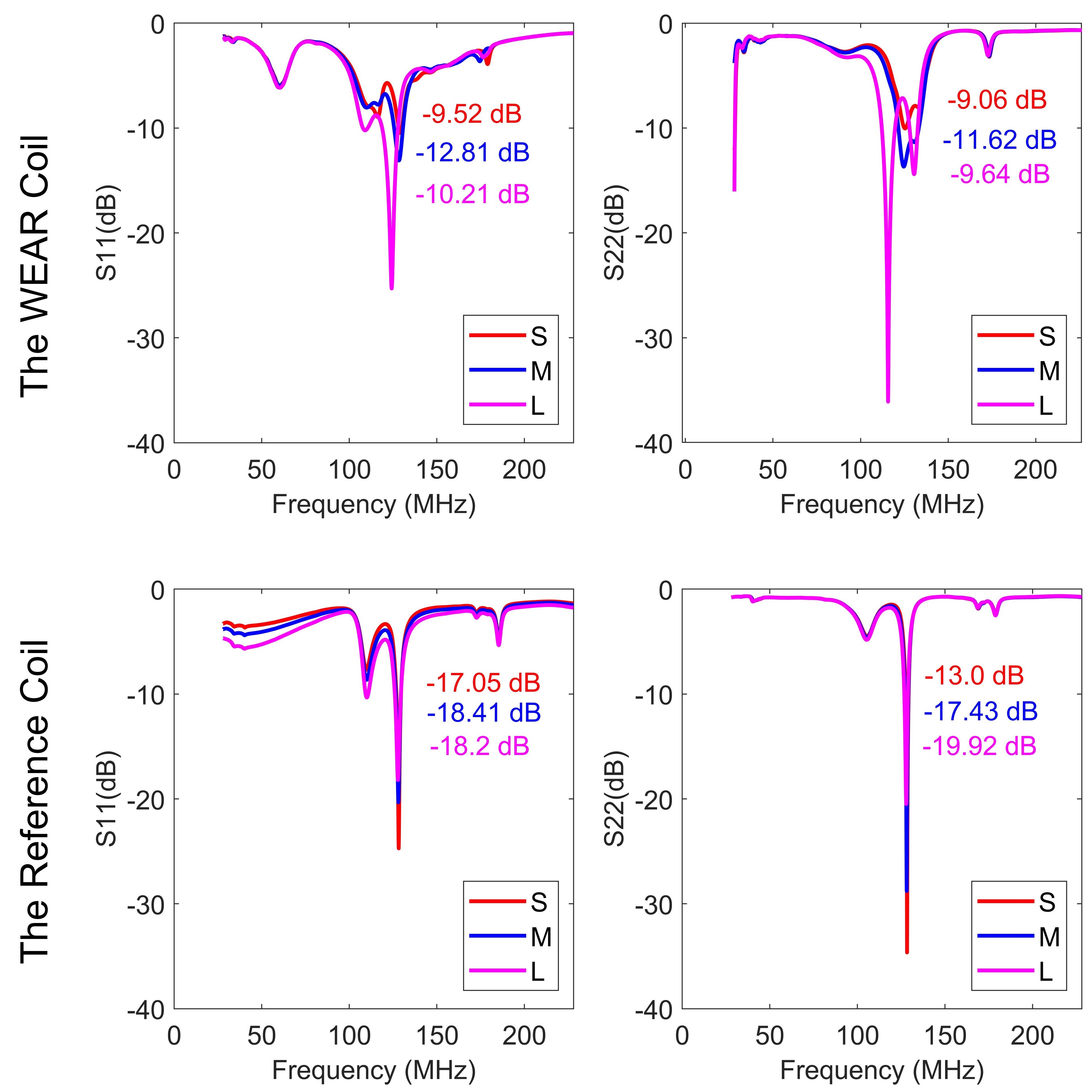
Figure 4: S11 of the WEAR coil at 127.7MHz on the S, the M, and the L phantom is -9.52dB, -12.81dB, and -10.21dB, respectively. S22 of the WEAR coil at 127.7MHz on the S, the M, and the L phantom is -9.06dB, -11.62dB, and -9.64.21dB, respectively. S11 of the reference coil at 127.7MHz on the S, the M, and the L phantom is -17.05dB, -18.41dB, and -18.2dB, respectively. S22 of the reference coil at 127.7MHz on the S, the M, and the L phantom is -13.0dB, -18.43dB, and -19.92dB, respectively.
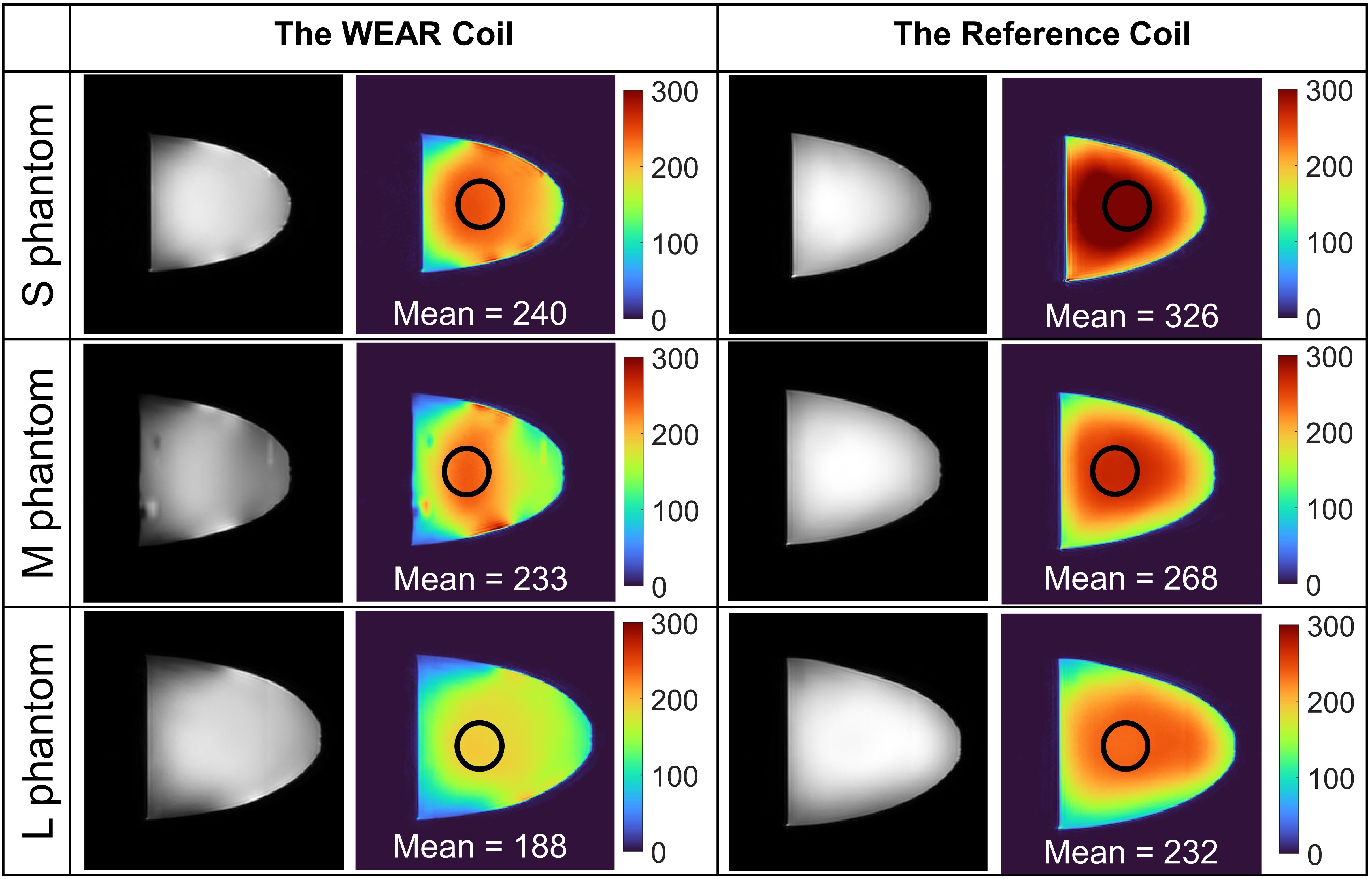
Figure 5: Phantom images of the WEAR coil and the reference coil when they were loaded with the S, the M, and the L phantoms. The mean SNR of the circular area of the WEAR coil for the S, the M, and the L phantom are 240, 233, and 188, respectively. The mean SNR of the circular area of the reference coil for the S, the M, and the L phantom are 326, 268, and 232, respectively. The SNR decrease in the WEAR coil on the S, the M, and the L phantom is 26%, 10%, and 13.5% compared to the reference coil.