1583
Expandable Transmission Line Resonators for Intraventricular 19F MRI1Division of Medical Physics, Department of Radiology, Medical Center - University of Freiburg, University of Freiburg, Freiburg, Germany
Synopsis
Keywords: Non-Array RF Coils, Antennas & Waveguides, Non-Array RF Coils, Antennas & Waveguides, Active catheter, Interventional Devices, Flexible Coils
Motivation: 19F-MRI can be used to monitor immune cell response to myocardial infarction, yet the low signal-to-noise ratio in the myocardium must be compensated by long measurement times and low spatial resolution.
Goal(s): To enable high spatial and temporal resolution 19F-MRI using an intraventricular expanding RF coil that can be introduced via a catheter.
Approach: A superelastic, self-resonant shielded-loop-resonator was developed to fit into a guiding catheter and the SNR was measured for different coil shapes.
Results: The expandable coil does not require re-tuning even at extreme shape deformations, and it can even be used as an active marker for real time 1H guidance.
Impact: Intraventricular MRI of 19F-labeled immune cells will enable effective monitoring at myocardial infarction after fluorine labeling. The expandable SLR coil can be inserted via guiding catheters and used as 1H tracking coil without tuning or additional adjustments.
Introduction
Endoluminal RF coils have been proposed to improve the signal-to-noise ratio (SNR) in intravascular and intraventricular applications [1]–[9]. Small endoluminal RF coils increase the SNR by maximizing the filling ratio; and they receive less noise from the body [10], [11]. A high SNR is especially important for X nuclear applications such as 19F MRI to overcome the long acquisition times and low spatial resolution [12], [13]. High performance RF coils can accelerate clinical translation of 19F MRI for monitoring of 19F-labeled immune cell response to myocardial infarction [14]–[20].Intravascular coils can be delivered through catheters; however, small coils that fit inside a catheter lumen are useful for tracking [21]–[24], but provide only a limited sensitive volume. To overcome this limitation, expandable loop coils were proposed [2], [9] which need to be re-tuned after expanding or have a fixed tuning which is then compromised if a different shape deformation occurs at the target. Loopless antennae can solve the size problem, but they are only sensitive in close vicinity to the antenna [6]–[8]. Here we introduce a transmission line resonator as an endoluminal RF coil which is expandable and remains tuned independent of its shape.
Methods
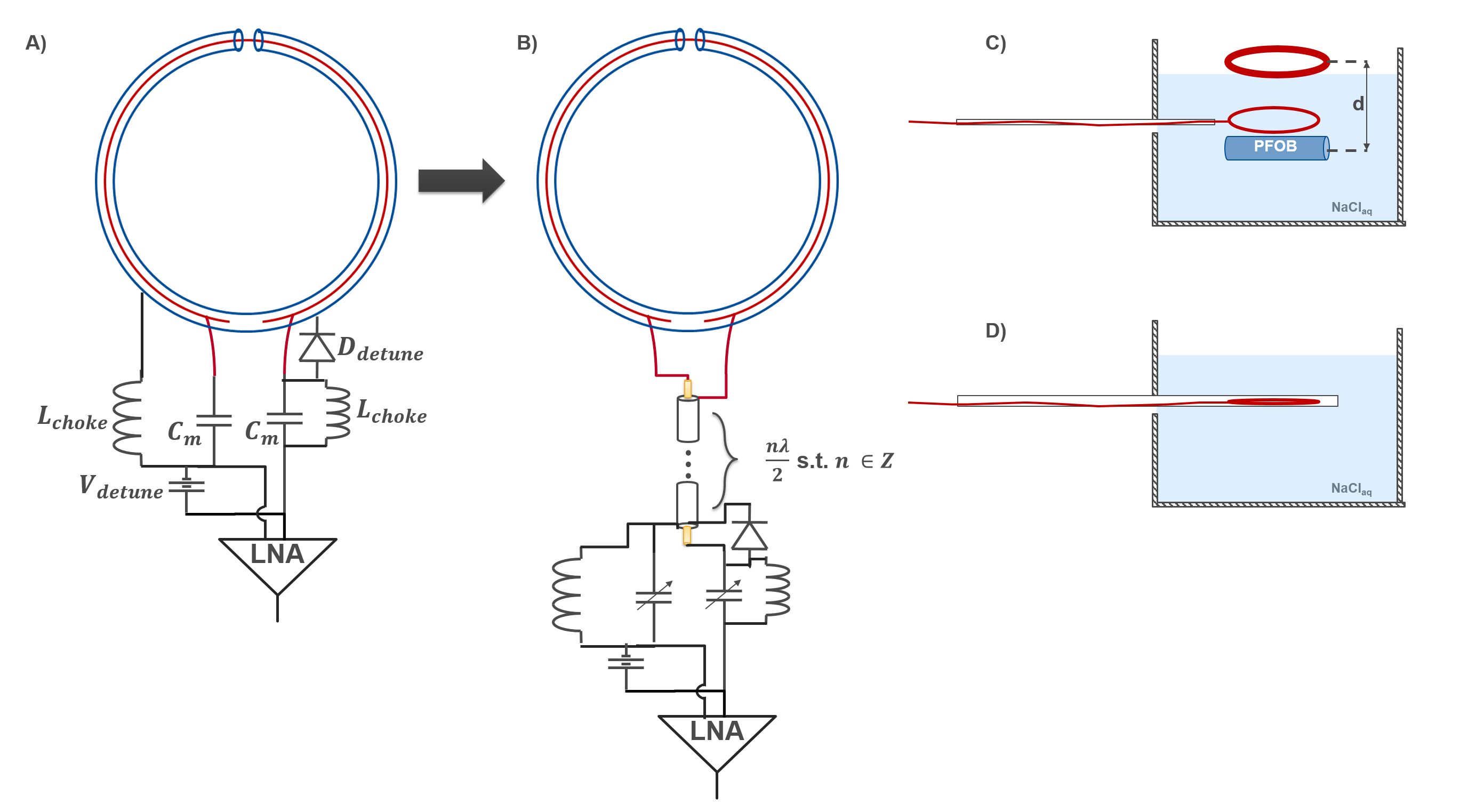
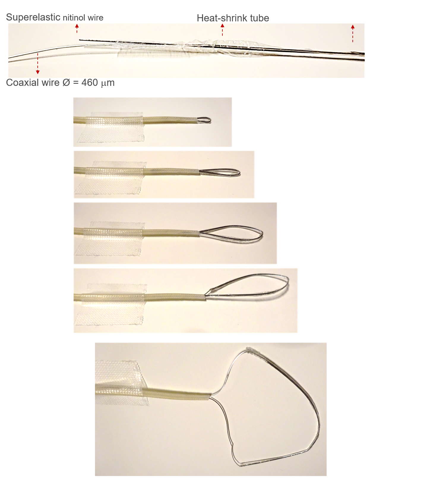
Resonance of an SLR depends on coaxial cable dimensions, length, and electromagnetic properties of the dielectric between inner and outer conductors [25]–[31]. Although capacitive or inductive tuning is possible, we designed self-resonant SLRs as they provide higher SNR, and use less lumped elements making it easier to fit them into a catheter [29]. As a proof of principle, an SLR of 75mm loop diameter was constructed using a coaxial cable with 1.2 mm outer diameter. Conventional and remote-matched SLRs were used for measurements (Fig. 1). In the guiding catheter, the SLR is streched to a straight shape (Fig. 2). Ideally, inner conductor of the coaxial cable is made of a superelastic alloy which recover its original loop shape outside the catheter for MR imaging. In this work, a nitinol wire was attached to the coil using a heat-shrink tube (Fig. 2), to provide elasticity to the coil form as a proof of principle. Another coil using a coaxial cable (Ø = 460 mm) was also constructed to fit inside a 8F guiding catheter.Intraventricular coil (ivSLR) was tuned to the 19F Larmor frequency at 3T (115.9 MHz). Because this frequency is close to 1H Larmor frequency, its utility for visual guidance during MR-guided interventions was also tested at a clinical 3T MRI system (PrismaFit, Siemens). SNR of the ivSLR was compared to an external loop coil at 3T (Fig. 1). For 1H tracking, a real-time trueFISP sequence was used (TR/TE= 3/1.5ms, FoV=280x280mm2, Res=176; a=20°, BW=977Hz/px). For SNR comparison, a 3D FLASH sequence was used (TR/TE=8.4/4ms,a=30°,FOV=256x256mm2,Res=128,Voxel size=2x2x2mm3,BW=280Hz/px) to image a 15 ml-Falcon tube filled with perfluor-polyether (Fomblin©), immersed in a container with saline solution.
Results
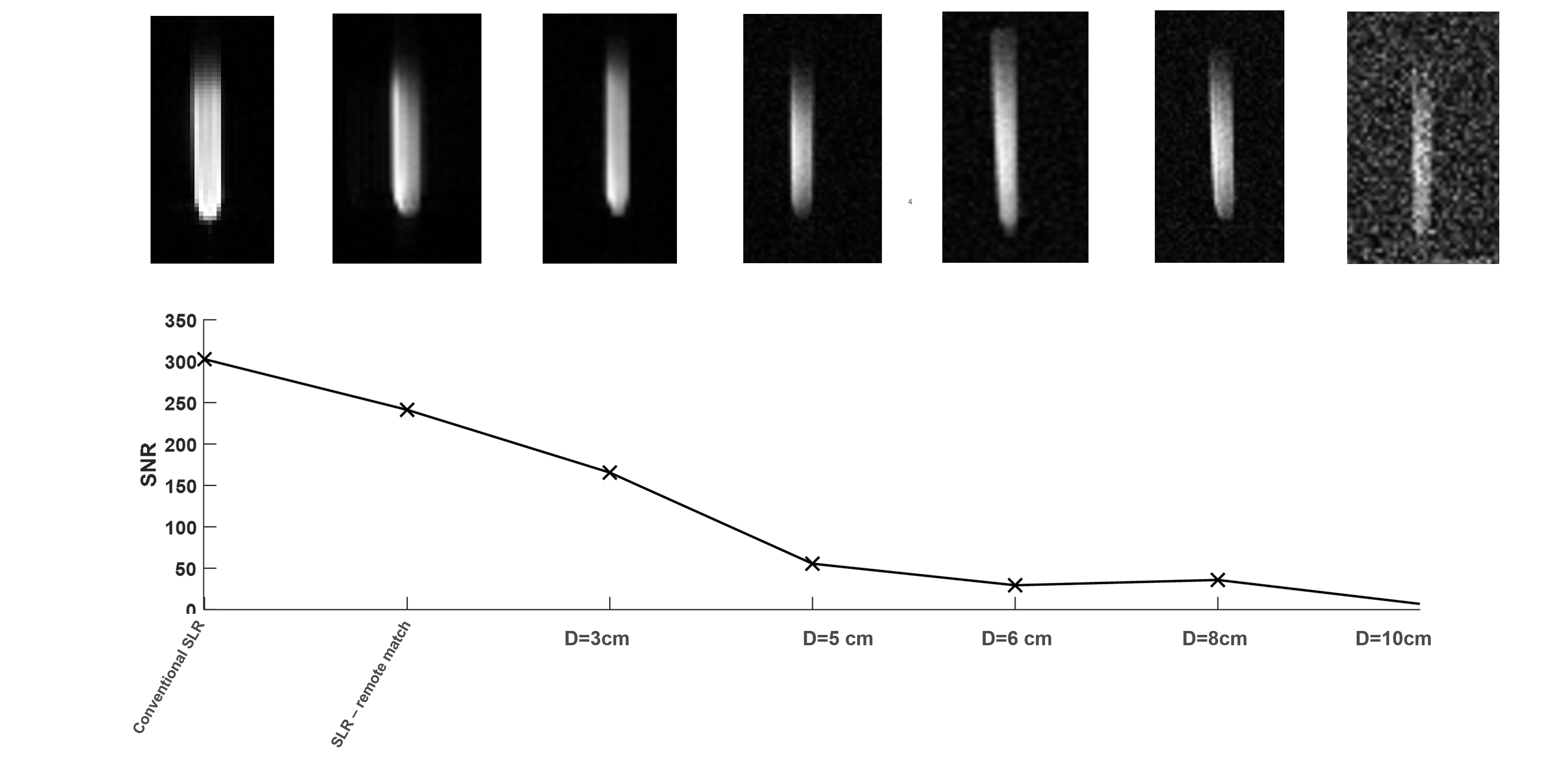
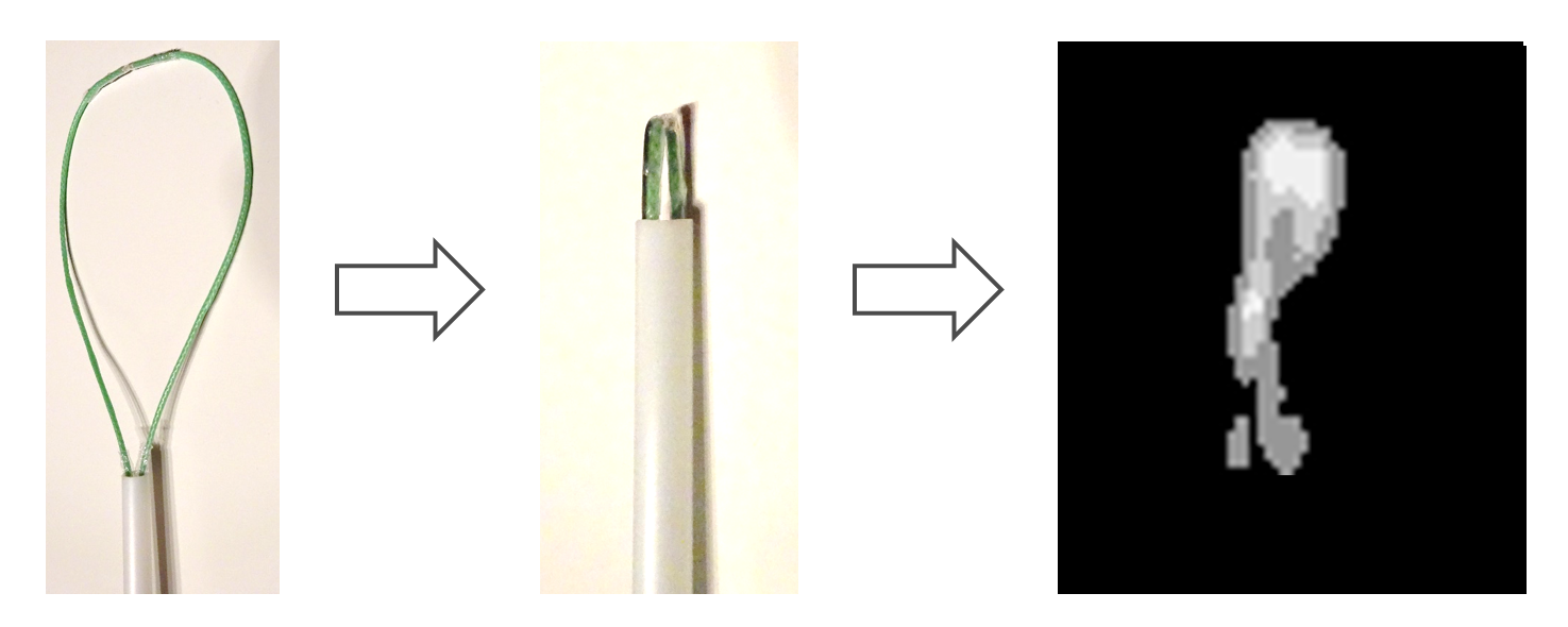
Larmor frequency shift of ivSLR for fully expanded and collapsed forms is below 0.2 MHz without any readjustments of the matching network, when fully immersed in water. Mean SNR of the 19F compound is plotted in Fig. 3 for increasing distance to the external surface coil and for on-coil matched and remote-matched ivSLRs (distance = 0). ivSLR provides over 80% SNR gain even for an external surface coil that is 3 cm away from the target region. Compared to on-coil matching, remote-matched SLR provides 20% lower SNR, but still outperforms external coils by at least 45%. 1H MRI with the ivSLR inside the guiding catheter shows that the same coil can also be used as active marker at the 1H frequency for visual guidance during real-time MRI (Fig. 4).Discussion
The proposed ivSLR can be used for high resolution intraventricular 19F MRI and for active tracking at the 1H frequency. Depending on the body size, the myocardial tissue can be located at 3 to 10cm in depth from the skin, where an ivSLR can provide up to 40-fold higher SNR than an external surface coil. Current prototype can be improved by use of custom-made coaxial wires with the inner conductor made of a superelastic alloy. Further animal experiments are needed to test the imaging performance and the safety of ivSLRs.SNR for 1H tracking images was lower than 10, which might be difficult to detect when underlying anatomy has high contrast. A low profile PIN diode based switch can be used to implement detuning to 1H Larmor frequency to improve visual guidance.
Acknowledgements
This study is funded by the Deutsche Forschungsgemeinschaft (DFG) as part of the SFB1425 (#422681845) project P15 and through an individual grant (#492563001).References
[1] E. Atalar et al., “High resolution intravascular MRI and MRS by using a catheter receiver coil,” Magn. Reson. Med., vol. 36, no. 4, pp. 596–605, 1996, doi: 10.1002/mrm.1910360415.
[2] H. H. Quick et al., “Single-loop coil concepts for intravascular magnetic resonance imaging,” Magn. Reson. Med., vol. 41, no. 4, pp. 751–758, 1999, doi: 10.1002/(SICI)1522-2594(199904)41:4<751::AID-MRM14>3.0.CO;2-V.
[3] G. C. Hurst, J. Hua, J. L. Duerk, and A. M. Cohen, “Intravascular (catheter) NMR receiver probe: Preliminary design analysis and application to canine iliofemoral imaging,” Magn. Reson. Med., vol. 24, no. 2, pp. 343–357, 1992, doi: 10.1002/mrm.1910240215.
[4] C. M. Hillenbrand et al., “Active device tracking and high-resolution intravascular MRI using a novel catheter-based, opposed-solenoid phased array coil,” Magn. Reson. Med., vol. 51, no. 4, pp. 668–675, Apr. 2004, doi: 10.1002/mrm.20050.
[5] B. Qiu et al., “Development of a 0.014-inch magnetic resonance imaging guidewire,” Magn. Reson. Med., vol. 53, no. 4, pp. 986–990, 2005, doi: 10.1002/mrm.20384.
[6] D. Qian, A. E. M. M. El-Sharkawy, E. Atalar, and P. A. Bottomley, “Interventional MRI: Tapering improves the distal sensitivity of the loopless antenna,” Magn. Reson. Med., vol. 63, no. 3, pp. 797–802, 2010, doi: 10.1002/mrm.22152.
[7] H. Çelik, Y. Eryaman, A. Altintaş, I. A. Abdel-Hafez, and E. Atalar, “Evaluation of internal MRI coils using ultimate intrinsic SNR,” Magn. Reson. Med., vol. 52, no. 3, pp. 640–649, 2004, doi: 10.1002/mrm.20200.
[8] R. C. Susil, C. J. Yeung, and E. Atalar, “Intravascular extended sensitivity (IVES) MRI antennas,” Magn. Reson. Med., vol. 50, no. 2, pp. 383–390, 2003, doi: 10.1002/mrm.10506.
[9] A. Homagk et al., “An expandable catheter loop coil for intravascular MRI in larger blood vessels,” Magn. Reson. Med., vol. 63, no. 2, pp. 517–523, Feb. 2010, doi: 10.1002/mrm.22228.
[10] A. Macovski, “Noise in MRI,” Magn. Reson. Med., vol. 36, no. 3, pp. 494–497, Sep. 1996, doi: 10.1002/mrm.1910360327.
[11] D. I. Hoult and R. E. Richards, “The signal-to-noise ratio of the nuclear magnetic resonance experiment,” J. Magn. Reson., vol. 213, no. 2, pp. 329–343, Dec. 2011, doi: 10.1016/j.jmr.2011.09.018.
[12] R. Hu, D. Kleimaier, M. Malzacher, M. A. U. Hoesl, N. K. Paschke, and L. R. Schad, “X‐nuclei imaging: Current state, technical challenges, and future directions,” J. Magn. Reson. Imaging, vol. 51, no. 2, pp. 355–376, Feb. 2020, doi: 10.1002/jmri.26780.
[13] C. H. Choi, S. M. Hong, J. Felder, and N. J. Shah, “The state-of-the-art and emerging design approaches of double-tuned RF coils for X-nuclei, brain MR imaging and spectroscopy: A review,” Magn. Reson. Imaging, vol. 72, no. April, pp. 103–116, 2020, doi: 10.1016/j.mri.2020.07.003.
[14] M. Rothe et al., “In vivo 19F MR inflammation imaging after myocardial infarction in a large animal model at 3 T,” Magn. Reson. Mater. Physics, Biol. Med., vol. 32, no. 1, pp. 5–13, Feb. 2019, doi: 10.1007/s10334-018-0714-8.
[15] F. Bönner et al., “Regional analysis of inflammation and contractile function in reperfused acute myocardial infarction by in vivo 19F cardiovascular magnetic resonance in pigs,” Basic Res. Cardiol., vol. 117, no. 1, p. 21, Dec. 2022, doi: 10.1007/s00395-022-00928-5.
[16] A. Maunder, M. Rao, F. Robb, and J. M. Wild, “Comparison of MEMS switches and PIN diodes for switched dual tuned RF coils,” Magn. Reson. Med., vol. 80, no. 4, pp. 1746–1753, 2018, doi: 10.1002/mrm.27156.
[17] L. Hu et al., “A generalized strategy for designing 19F/1H dual-frequency MRI coil for small animal imaging at 4.7 Tesla,” J. Magn. Reson. Imaging, vol. 34, no. 1, pp. 245–252, Jul. 2011, doi: 10.1002/jmri.22516.
[18] C. H. Choi, S. M. Hong, Y. H. Ha, and N. J. Shah, “Design and construction of a novel 1H/19F double-tuned coil system using PIN-diode switches at 9.4 T,” J. Magn. Reson., vol. 279, pp. 11–15, 2017, doi: 10.1016/j.jmr.2017.04.005.
[19] A. C. Özen et al., “Scalable and modular <scp>8‐channel</scp> transmit and <scp>8‐channel</scp> flexible receive coil array for <scp> 19 F MRI </scp> of large animals,” Magn. Reson. Med., vol. 89, no. 3, pp. 1237–1250, Mar. 2023, doi: 10.1002/mrm.29490.
[20] Y. Ji et al., “Eight-channel transceiver RF coil array tailored for 1H/19F MR of the human knee and fluorinated drugs at 7.0 T,” NMR Biomed., vol. 28, no. 6, pp. 726–737, 2015, doi: 10.1002/nbm.3300.
[21] C. L. Dumoulin, R. P. Mallozzi, R. D. Darrow, and E. J. Schmidt, “Phase-field dithering for active catheter tracking,” Magn. Reson. Med., vol. 63, no. 5, pp. 1398–1403, 2010, doi: 10.1002/mrm.22297.
[22] O. Kocaturk et al., “Whole shaft visibility and mechanical performance for active MR catheters using copper-nitinol braided polymer tubes,” J. Cardiovasc. Magn. Reson., vol. 11, no. 1, p. 29, Dec. 2009, doi: 10.1186/1532-429X-11-29.
[23] M. Bock et al., “Active catheter tracking using parallel MRI and real-time image reconstruction,” Magn. Reson. Med., vol. 55, no. 6, pp. 1454–1459, Jun. 2006, doi: 10.1002/mrm.20902.
[24] A. Alipour et al., “Mri conditional actively tracked metallic electrophysiology catheters and guidewires with miniature tethered radio-frequency traps: Theory, design, and validation,” IEEE Trans. Biomed. Eng., vol. 67, no. 6, pp. 1616–1627, 2020, doi: 10.1109/TBME.2019.2941460.
[25] H. J. Zabel, R. Bader, J. Gehrig, and W. J. Lorenz, “High-quality MR imaging with flexible transmission line resonators.,” Radiology, vol. 165, no. 3, pp. 857–859, Dec. 1987, doi: 10.1148/radiology.165.3.3685365.
[26] M. D. Harpen, “The Theory of Shielded Loop Resonators,” Magn. Reson. Med., vol. 32, pp. 785–788, 1994.
[27] A. Stensgaard, “Optimized design of the shielded-loop resonator,” J. Magn. Reson. - Ser. A, vol. 122, no. 2, pp. 120–125, 1996, doi: 10.1006/jmra.1996.0187.
[28] T. Ruytenberg, A. Webb, and I. Zivkovic, “Shielded‐coaxial‐cable coils as receive and transceive array elements for 7T human MRI,” Magn. Reson. Med., vol. 83, no. 3, pp. 1135–1146, Mar. 2020, doi: 10.1002/mrm.27964.
[29] M. Sreereddy, M. Bock, and A. C. Özen, “Optimization and Analysis of Shielded Loop Resonators towards Modular Coil Arrays,” in Proc. Intl. Soc. Mag. Reson. Med. 30, 2022, p. 47.
[30] L. Nohava et al., “Flexible Multi-Turn Multi-Gap Coaxial RF Coils: Design Concept and Implementation for Magnetic Resonance Imaging at 3 and 7 Tesla,” IEEE Trans. Med. Imaging, vol. 40, no. 4, pp. 1267–1278, Apr. 2021, doi: 10.1109/TMI.2021.3051390.
[31] B. Zhang, D. K. Sodickson, and M. A. Cloos, “A high-impedance detector-array glove for magnetic resonance imaging of the hand,” Nat. Biomed. Eng., vol. 2, no. 8, pp. 570–577, Aug. 2018, doi: 10.1038/s41551-018-0233-y.
Figures