1582
Active Shielding of RF Traps1Skope MRT, Zurich, Switzerland
Synopsis
Keywords: RF Arrays & Systems, RF Arrays & Systems, Balun and RF traps
Motivation: Baluns and RF traps are resonant structures and coupling among each other, as well as to receive and transmit coils must be avoided. This is a particular challenge for the efficient and compact class of wound inductor traps.
Goal(s): Wound inductor trap that is isolated from external fields, does not require metallic shielding surfaces and can be wound compactly also for cables with limited bending radius.
Approach: Employing the method of active shielding known from gradient coil design to RF trap inductors.
Results: RF traps with shielding properties comparable to metal sheath shielded versions with very low eddy current profile.
Impact: Compact and efficient RF traps can help to design better and safer RF coils. Requiring no metal sheath for shielding of the trap can help to reduce gradient-switching-induced vibrations and heating.
Introduction
Common-mode-currents or RF sheath-waves on cabling in the bore can lead to RF burns in tissue close to the cabling and the RF coil conductor, eventually harm system components or lead to performance degradation of RF coils and other systems entering the magnet bore. Their suppression is therefore of paramount importance for safe and efficient operation of MRI compatible devices and is a major concern in MRI coil building. Correspondingly, a large variety of RF traps and baluns exist such as coiled traps [1], sleeve baluns [2], or floating traps [3, 4]. The sheath-waves are thereby suppressed by parallel resonance in the trap generating a large effective series common-mode-impedance. However, this resonance in the trap tends to detrimentally couple to other RF traps or coils in particular for coiled geometries. Coiled RF traps are mostly applied for their compact formfactor and efficiency. To avoid coupling to other traps or circuits they have either a self-shielding-winding such as toroidal or figure-8, or an external conductive shield surface. However, the former leads typically to substantially larger formfactors often limited by the minimum bending radius of the cable, the latter has a tendency to generate gradient eddy currents and concomitantly vibrations in the systems.Methods
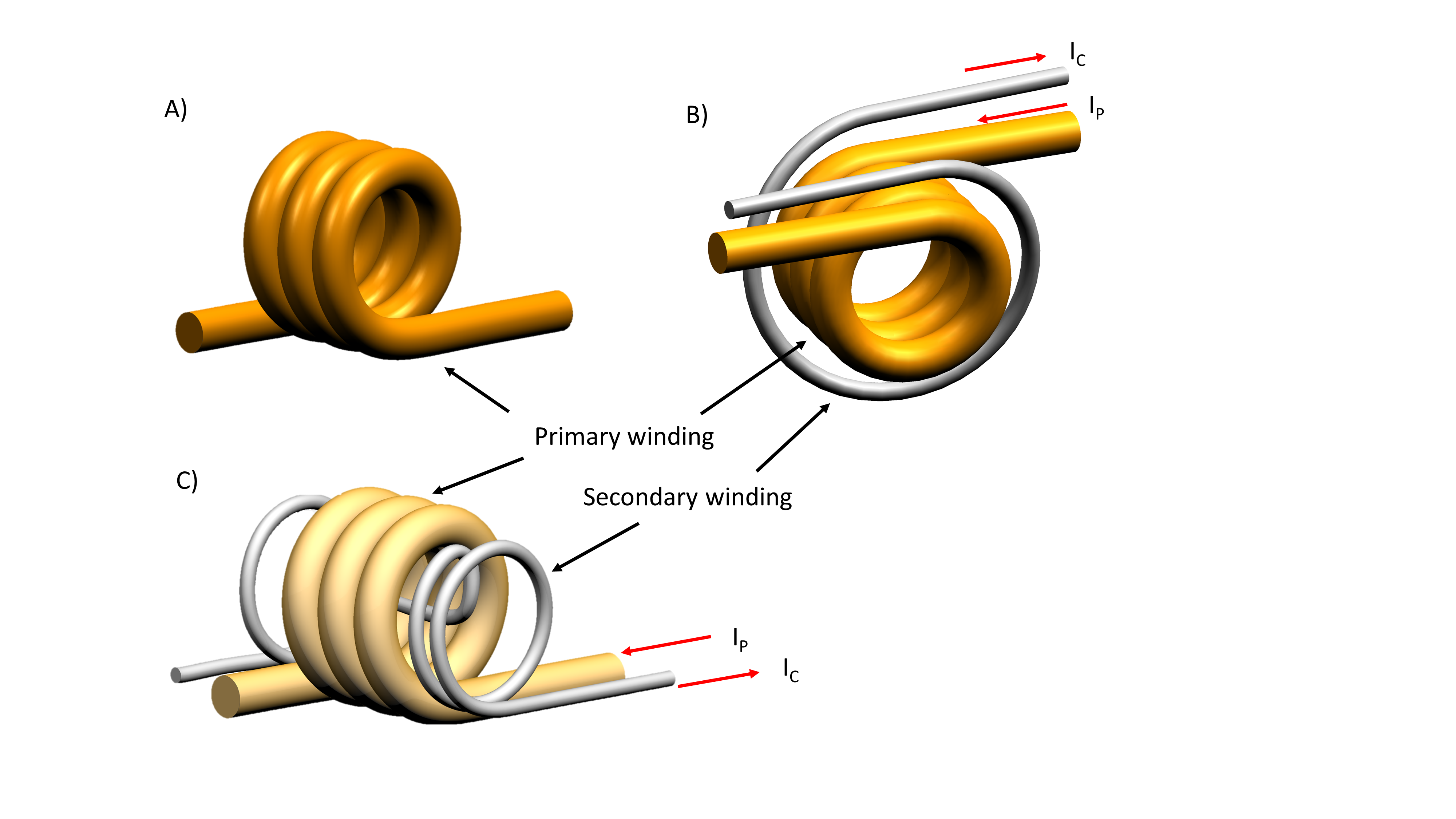
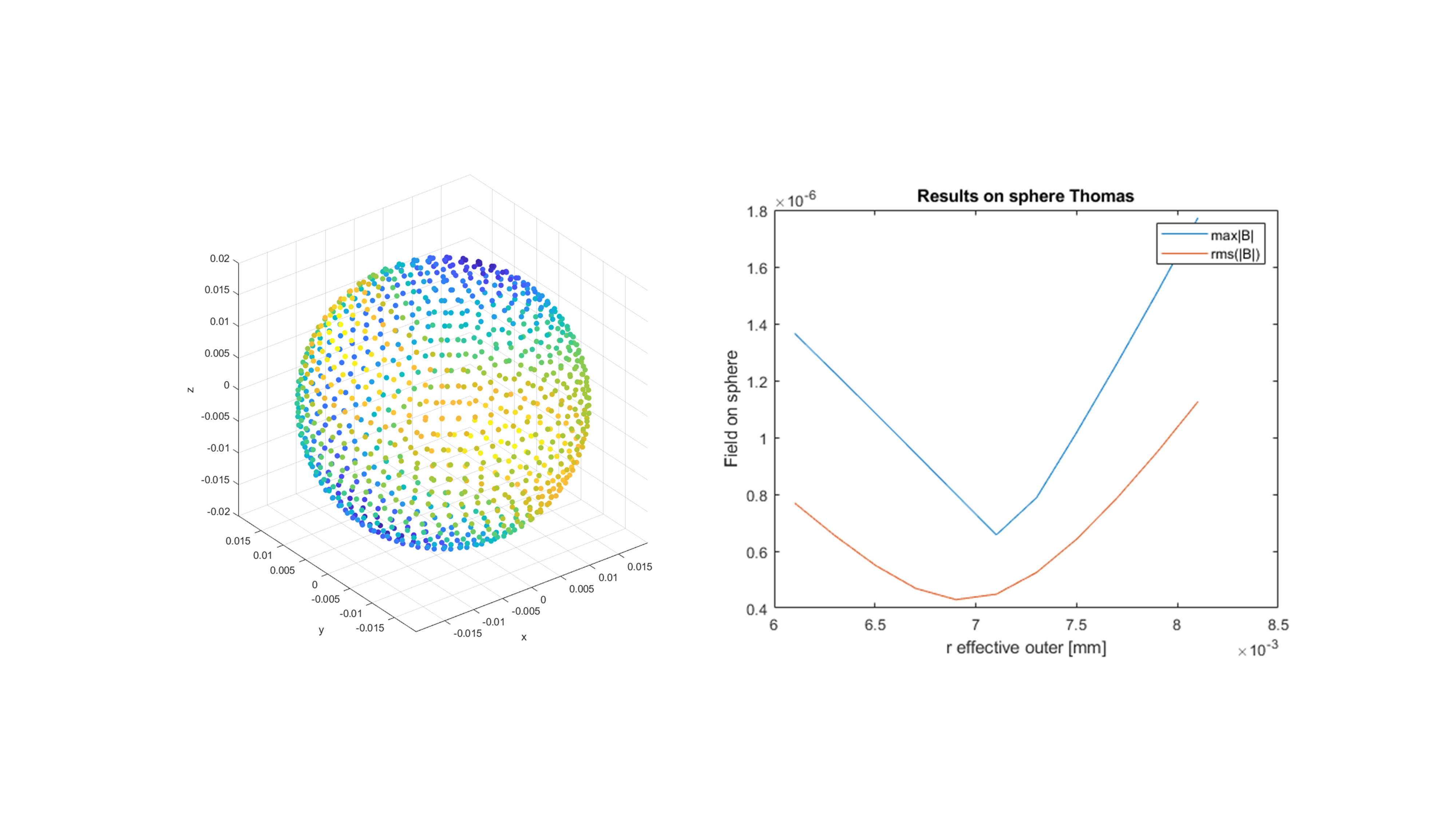
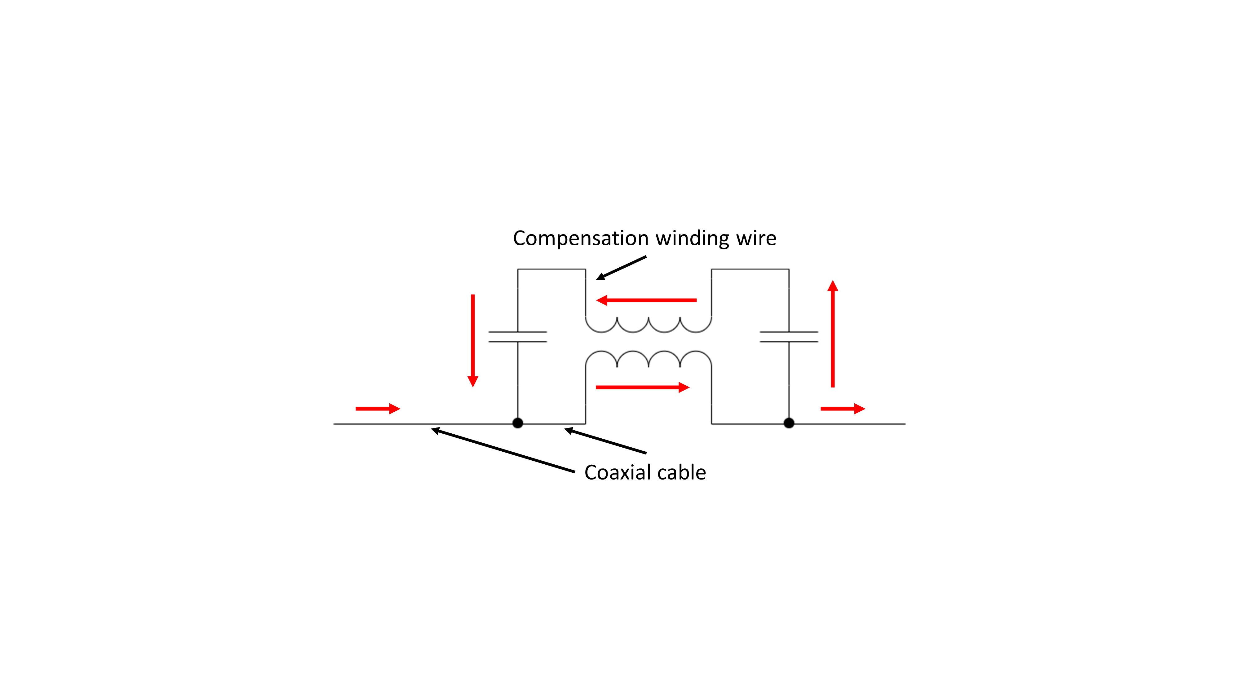
We propose an approach [5] inspired by active shielding [6] commonly employed in magnet and gradient coil design. A secondary winding is designed to suppress the field of the primary winding outside the coil assembly. The secondary winding is then driven either by the return current of the primary winding (shown here) or an active source. The geometry of the compensation current pattern can in principle be determined and implemented by analogous methods as in the case of gradient coils such as stream-function based target-field methods and inlaid wires or structured plane conductors. However, often heuristic geometrical parametrizations can lead to good suppression of the outside field produced by the trap. Figure 1 shows two examples of compensated trap configurations. In B) and external counter winding along the trap is used and in C) the counter windings are joining the primary solenoid. In both geometries, the compensation winding produce magnetic fields in the opposite longitudinal direction with respect to the primary coil. A suppression of external fields produced by the trap is expected to reduce coupling to outer fields and circuits by reciprocity. At high frequencies, the current is not equally distributed on the conductors gains relevance. Estimations based on approximations for the effective diameter of RF solenoid [e.g. 7] can be employed. The optimal parameters can also be refined by approximative or full-wave field simulations as shown in Figure 2. The primary and the secondary winding are resonated as shown in Figure 3. The circuit thereby provides the current to the compensation winding by the resonance at the frequency of operation. For demonstration, RF traps for 7T have been implement using 0.086’’-diameter, hand-formable cables which are comparably thick and have a large bending radius. The inner diameter of the winding was 7mm, the resulting in a form factor of 13.5mmx12mm for B). Primary and secondary windings were inlaid around 3D-printed formers from flame retardant materials and high temperature resistance. This process delivered a high reproducibility and efficient manufacturing.Results
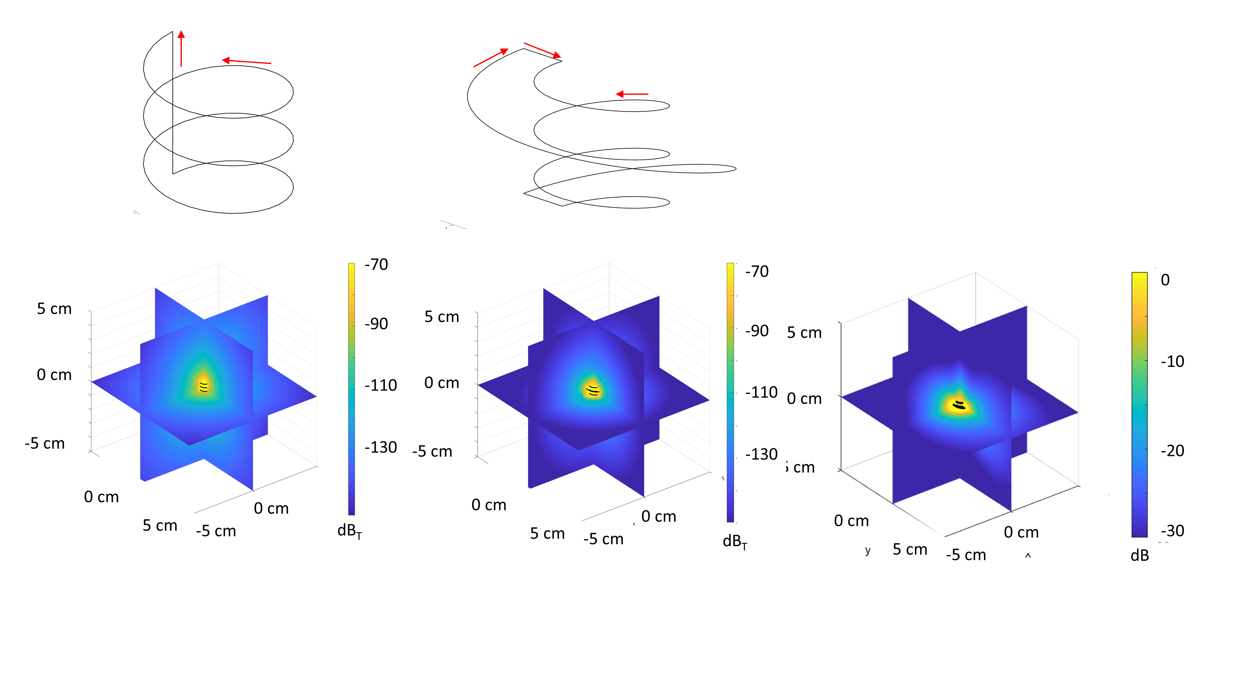
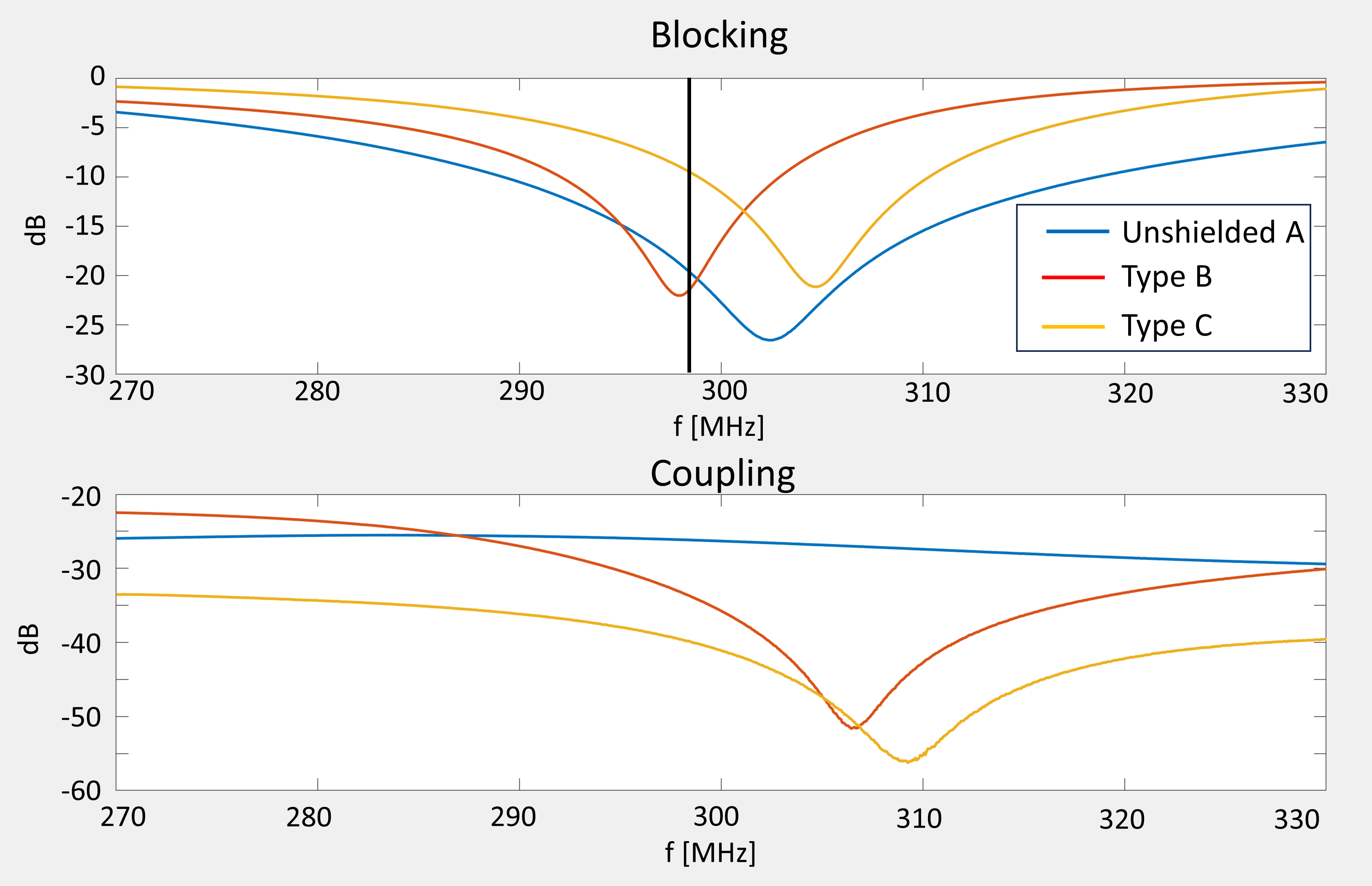
The field simulations show (Figure 4) a suppression of the external field of about 30dB even comparably close to the trap. This is expected to suppress coupling to neighboring traps and RF coils. Blocking was measured along with the coupling to an external field produced by a pick-up loop into the trap using a network analyzer and test cable. As seen in Figure 5, the active compensation winding induces a reduction in efficiency of the RF trap mainly due to a reduction in inductance. However, the resonant behavior with respect to external fields is suppressed as seen by the very low coupling to the external pick-up loop.Discussion
The present approach allows to design compact, coiled RF traps with low coupling to external fields and other resonant circuits. The compensation windings can be made of various conductor types and can thereby be very freely shaped as opposed to employing the coaxial cable itself for compensation. The presented model B) and C) for instance would each require very sharp bends of the cable for entering or in the compensation winding.Acknowledgements
No acknowledgement found.References
1) Harrison et al. RF COIL COUPLING FOR MRI WITH TUNED RF REJECTION CIRCUIT USING COAX SHIELD CHOKE, Patent US 4 682 125, 1987 2) H.O. Roosenstein, Shielded Antenna Feeder Lead or Line, Patent, US 2 322 971, 1940 3) D. Seeber, J. Jevtic, A Menon, Floating Radio Frequency Balun for Suppression of Shield Currents, Conc. Magn Reson B, 2004 4) E Karasan,et al. Caterpillar traps: A highly flexible, distributed system of toroidal cable traps, Magn. Reson. Med, 2023 5) T. Schmid, D.O. Brunner, patent WO2019243274A1, 2019 6) R. Turner, Gradient coil design: A review of methods, MRI 1993 7) D. W. Knight, An introduction to the art of Solenoid Inductance Calculation With emphasis on radio-frequency applications, 2016Figures