1581
A Single-Solenoid Double-Resonance Radiofrequency Coil for 1H-31P Solid State MRI at 1.5 T1Radiology, Massachusetts General Hospital, Charlestown, MA, United States, 2Harvard Medical School, Boston, MA, United States, 3Worcester Polytechnic Institute, Worcester, MA, United States, 4Ansys Inc., Waltham, MA, United States
Synopsis
Keywords: Non-Array RF Coils, Antennas & Waveguides, Non-Array RF Coils, Antennas & Waveguides, Double-resonance coil, non-proton, skeletal and simulations
Motivation: Metabolic bone disease is a prevalent health concern affecting more than 200 million individuals worldwide. MRI has the potential to noninvasively characterize bone quality.
Goal(s): The goal was to custom-build a double-resonance RF coil capable of proton and phosphorus solid state MRI on a 1.5 T extremity scanner intended for arms, legs, and tissue specimen imaging.
Approach: A double-resonance RF coil was constructed based on a double-tuning single solenoid configuration, employing quarter-wave transmission lines to isolate the two channels.
Results: ZTE 1H and 31P MRI of bone specimens demonstrated the feasibility and effectiveness of this coil.
Impact: The constructed single-solenoid double-resonance RF coil is capable of acquiring solid state 1H and 31P MRI of bone specimens. With this coil, MR information on the organic matrix (1H) and mineral (31P) can be obtained to assess metabolic bone diseases.
Introduction
While typically used to image soft tissues, MRI is capable of directly scanning the mineral and organic matrix of solid bone. We custom-built a double-resonance RF coil for use in a 1.5 T extremity scanner, dedicated to measuring bone mineral density through both 1H and 31P imaging of ex vivo bone specimens.One typical strategy for designing a double-resonance RF coil employs a cross-coil configuration where two separate coils are positioned orthogonally for geometric decoupling1,2. This yields a zero mutual inductance between the two coils and therefore excellent isolation. However, the RF fields from the separate coils have different field distributions and reduced effectiveness for precise tracking between each other which is required in specialized solid state pulse sequences such as cross-polarization. In this work, a double-resonance RF coil is implemented by double-tuning a single inductor.
Coil Design and Construction
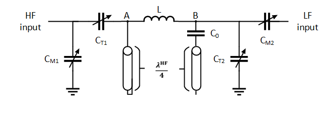
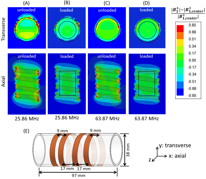
This double-resonance RF coil (Fig. 1) utilizes lumped elements and quarter-wave transmission lines to isolate the two channels3. Two 50Ω semirigid coax stubs with polyethylene foam dielectric (Andrew Microwave/CommScope Heliax FSJ1-50A), one short terminated and the other open terminated, are each 96 cm long, equivalent to the 1H quarter wavelength at 1.5 T, given a velocity factor of 0.82. Four ceramic non-magnetic high voltage trimmer capacitors (Sprague-Goodman SGNMNC3708) were used to adjust the resonant frequency and to minimize reactance losses via impedance matching, and a high-performance chip capacitor (American Technical Ceramics Corp, Fountain Inn, SC) was used to reduce the net capacitance of the open stub on the low-frequency side. The connections to the scanner were Teflon coaxial cables (Belden 88240) that contain no proton content to interfere with 1H solid state images. The proton content of the stubs is low because of the low density of the foam dielectric. The single-layer solenoid has 4 non-uniformly spaced turns with an inductance of 280 nH.To optimize the B1 field homogeneity, the spacings between turns at the ends of the solenoid were configured to be smaller than the central turn spacing. The end turn spacing (9 mm) of the solenoid was about half that of the central turn spacing (17 mm). Fig. 2 (A)-(D) shows the section plots of magnetic field deviation derived from simulations using the Ansys HFSS software. Overall, the solenoid exhibits a reasonable B1 uniformity, especially within the cylindrical region where the most intense RF field exists.
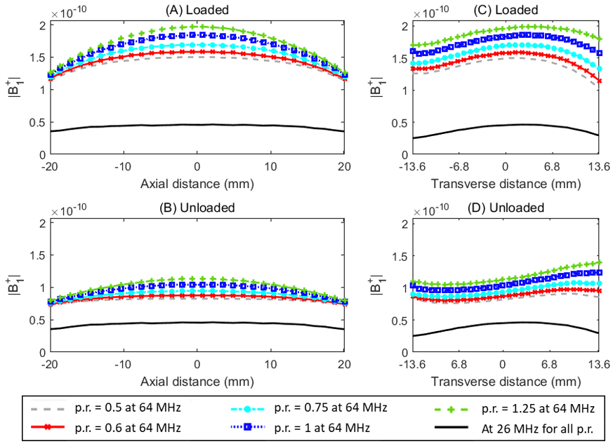
We further validated the B1 homogeneity by comparing field distribution of solenoid with pitch ratios (p.r., end-turn spacing divided by central turn spacing) of 0.5, 0.6, 0.75, 1 and 1.25 while the overall length and diameter held constant (Fig. 3). The best pitch ratio was 0.5, corresponding to our design of 9 mm outer spacing and 17 mm inner spacing. A pitch ratio smaller than 0.5 will create an overlap of adjacent turns.
Bench Tests and MRI Experiments
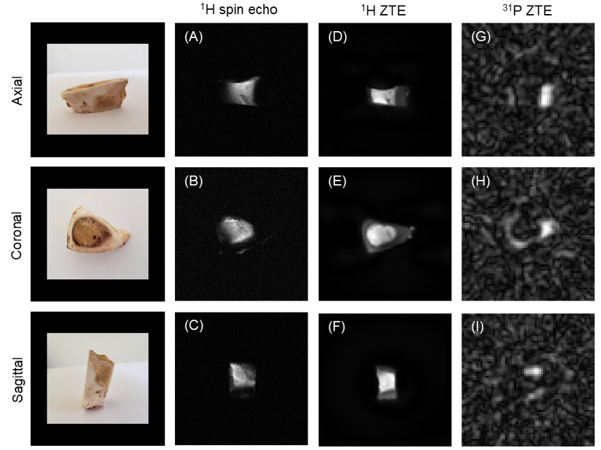
The double resonance coil showed sufficiently low reflected power <−30 dB for both nuclei (Table 1). The coil efficiency measured as the Q factor is reasonably high for 1H but relatively low for 31P. The Q-factor of 1H channel was reduced by 39% when loaded and by 35% for the 31P channel. The Q-ratios (QUL/QL) of both channels are comparable. MR images of a bone specimen were acquired using 1H spin echo, 1H zero echo time (ZTE) and 31P ZTE imaging sequences (Fig. 4). The single-slice 1H spin echo images were obtained with TR/TE = 200/77.11 ms, matrix size of 3842, FoV at 14.52 cm2, and NEX = 32 over 12 kHz bandwidth. The 1H ZTE images were acquired with TR = 5.63 ms, FoV = 19.02 cm2, receiver recovery time (end of the RF pulse to start of sampling) = 10 μs, flip angle = 13°, RF power = 26 W, number of spokes = 67k, number of complex points per spoke = 125, number of excitation (NEX) = 4, bandwidth = 195 kHz, no fat suppression. The 31P ZTE images were acquired with TR = 29 ms, FoV = 19.02 cm2, receiver recovery time = 10 μs, flip angle = 4°, RF power = 108 W, number of spokes = 15k, number of complex points per spoke = 50, NEX = 60, bandwidth = 91 kHz.Discussion and Conclusion
The 1H ZTE images show excellent SNR and contrast, whereas 31P ZTE images are noisy but still provide an adequate signal from mineral content that can be extracted with postprocessing algorithms using co-registered 1H images. This single-layer air-core solenoid is far larger than any double-tuned single-solenoid previously used for solid state MRI.Acknowledgements
This work is supported by U.S. National Institutes of Health grant R01AR075077. The magnet was developed by Superconducting Systems, Inc., Billerica, MA under NIH grant 4R44AR065903 (MRI scanner development subcontracted to MGH).References
- Kim, E.J., D. Kim, S. Lee, D. Heo, Y.H. Lee, and J.-S. Suh, Development of 1H-31P Animal RF Coil for pH Measurement Using a Clinical MR Scanner. J Korean Soc Magn Reson Med, 2014. 18(1): p. 52-58.
- Yan, X., R. Xue, and X. Zhang, A monopole/loop dual-tuned RF coil for ultrahigh field MRI. Quant Imaging Med Surg, 2014. 4(4): p. 225-31.
- Cross, V.R., R.K. Hester, and J.S. Waugh, Single coil probe with transmission‐line tuning for nuclear magnetic double resonance. Review of Scientific Instruments, 1976. 47(12): p. 1486-1488.
- Baltzis, K.B., The finite element method magnetics (FEMM) freeware package: May it serve as an educational tool in teaching electromagnetics? Education and Information Technologies, 2010. 15(1): p. 19-36.
Figures