1578
Triple-tunable birdcage coil for frequency selection in PET/MRI systems1Department of Health Sciences and Technology, GAIHST, Gachon University, Incheon, Korea, Republic of, 2Neuroscience Research Institute, Gachon University, Incheon, Korea, Republic of, 3Department of Nuclear Medicine, Seoul National Univeristy College of Medicine, Seoul, Korea, Republic of, 4Department of Biomedical Engineering, Gachon University, Seoungnam, Korea, Republic of
Synopsis
Keywords: Non-Array RF Coils, Antennas & Waveguides, Non-Array RF Coils, Antennas & Waveguides, Tirple-tunable, Stacked end-ring, Birdcage coil, Uniformity
Motivation: The PET insert can be used with MRI systems of different magnetic field strengths; however, a radio frequency(RF) coil cannot be used with different tesla.
Goal(s): Our goal is to generate uniform RF transmit magnetic fields at 3T, 7T and 11.74T MRI system using single RF coil.
Approach: Based on electromagnetic(EM) simulation, we proposed a new geometry of birdcage coil, which has 6 end-rings and 4 legs for triple resonance frequencies.
Results: In EM simulation, the proposed coil showed higher than 90% uniformity in the central axial plane. In bench measurement, proposed coil clearly showed triple resonance frequencies at 123.2, 297.2 and 500MHz.
Impact: Our proposed RF coil, named triple tunable birdcage coil, can generate uniform RF transmitted magnetic fields in 3T, 7T and 11.74T MRI systems. Therefore, it can be used for frequency selection in PET/MRI systems.
Introduction
The combination of imaging modalities that MRI and PET can provide simultaneous acquisition of high-resolution anatomical information and high-sensitivity metabolic information. Therefore, the PET inserts suitable for MRI have recently been developed1. However, in this PET/MRI configuration, the PET inserts were used in various frequency MRI system, however, the MR image acquisition has been limited to single-tuned radiofrequency(RF) coils. In recent years, a various multiple tuning technique has been proposed in RF coil2-4. Therefore, it became possible to acquire anatomical images using hydrogen and metabolic images using non-hydrogen. The birdcage coil, which can generate uniform transmit magnetic field(B1+), is also used for dual-tuned operation5. However, the dual-tuned birdcage coil with four end-rings has disadvantage of increased size and reduced B1+-intensity. In this study, we propose triple-tunable birdcage coil(TTBC), which minimized size increase and B1+-intensity degradation, for frequency selection in PET/MRI systems.Methods
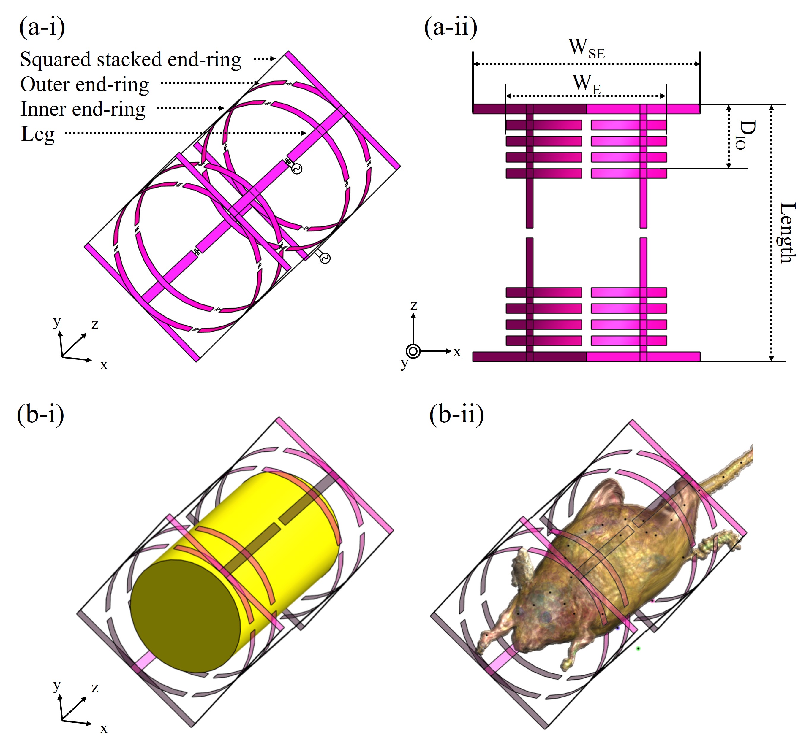
The TTBC(Fig.1(a)) was modeled using electromagnetic(EM) simulation(Sim4life by ZMT, www.zmt.swiss) and constructed by 4 shared legs and 6 end-rings. The length(z-axis) and diameter(x- and y-axis) of the TTBC was set to 80mm and 50mm, respectively. All conductors were set as perfect electric conductor and had a width of 3mm. the 6 end-rings(Fig.1(a-i)) can be distributed by outer end-ring, inner end-ring, and stacked end-ring. The outer end-rings were located at the edge of legs with circular shape, and the squared stacked end-rings were stacked on outer end-rings for minimized size increase in the z-axis direction. Finally, |B1+|-field distribution according to the position of the circular inner end-rings were compared. The widths of circular end-ring(WE) and squared stacked end-ring(WSE) were set to 50mm and 70.71mm, respectively. The two RF input ports were located on the legs with 90° difference for quadrature excitation, and the RF input power was normalized to 1W. The distance between inner and outer end-ring(DIO in Fig.1(a-ii)) was set from 5 to 20mm with 5mm intervals. For the comparison, the cylindrical phantom(Fig.1(b-i)), which has electrical properties of muscle tissue, with a diameter of 38mm and a length of 70mm, and the mouse phantom(Fig.1(b-ii)) were used. the electrical properties of each phantom were set to the values at the 123, 300 and 500MHz provided by IT’IS database. The TTBC with different DIO was tuned to 123, 300 and 500MHz using lumped capacitors. The |B1+|-intensity and |B1+|-uniformity calculated as normalized absolute average deviation6 were compared in the central axial and central coronal plane. The TTBC of the same size with EM simulation was manufactured, and the scattering(S-) parameters were measured by network analyzer.Results
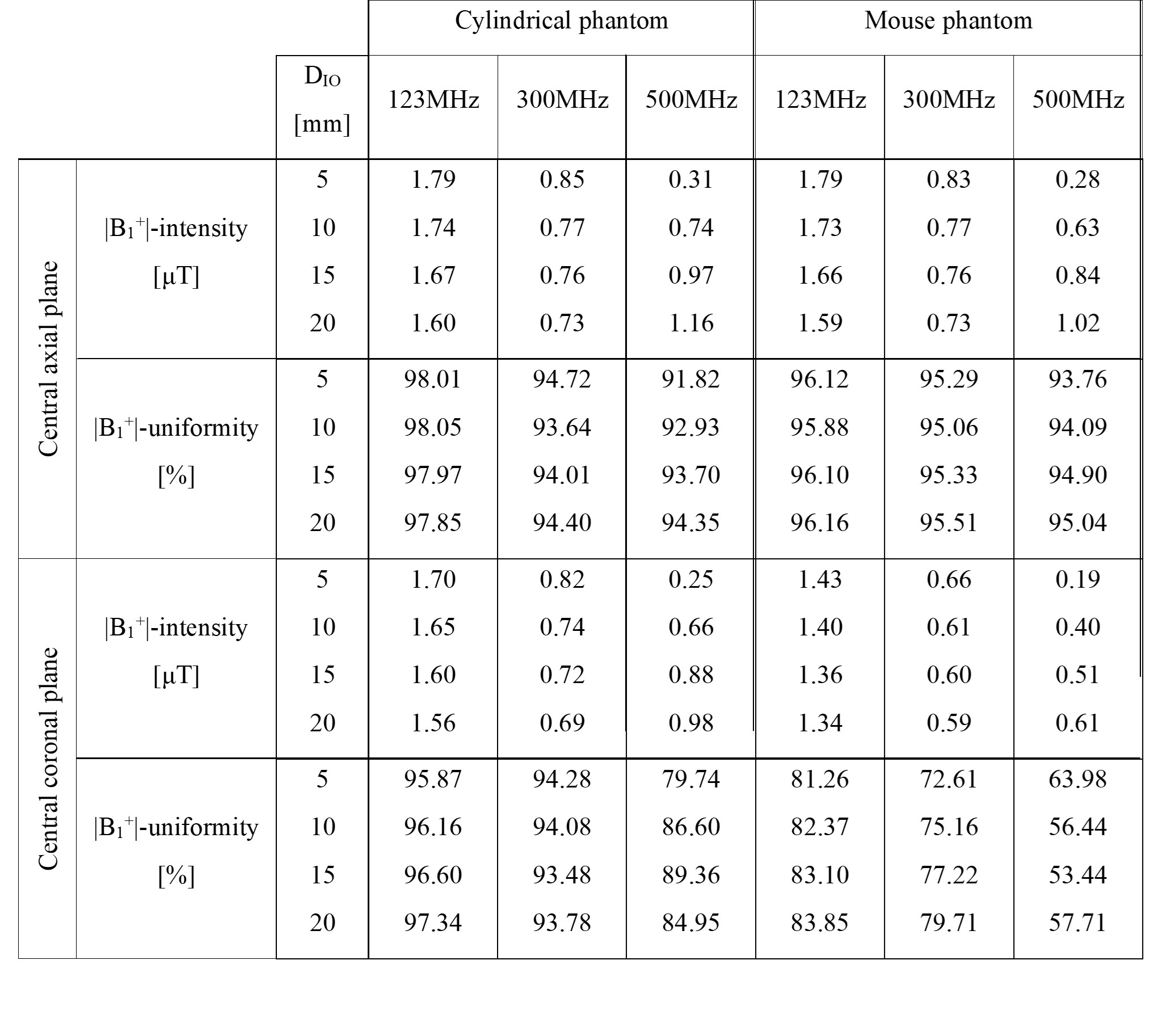
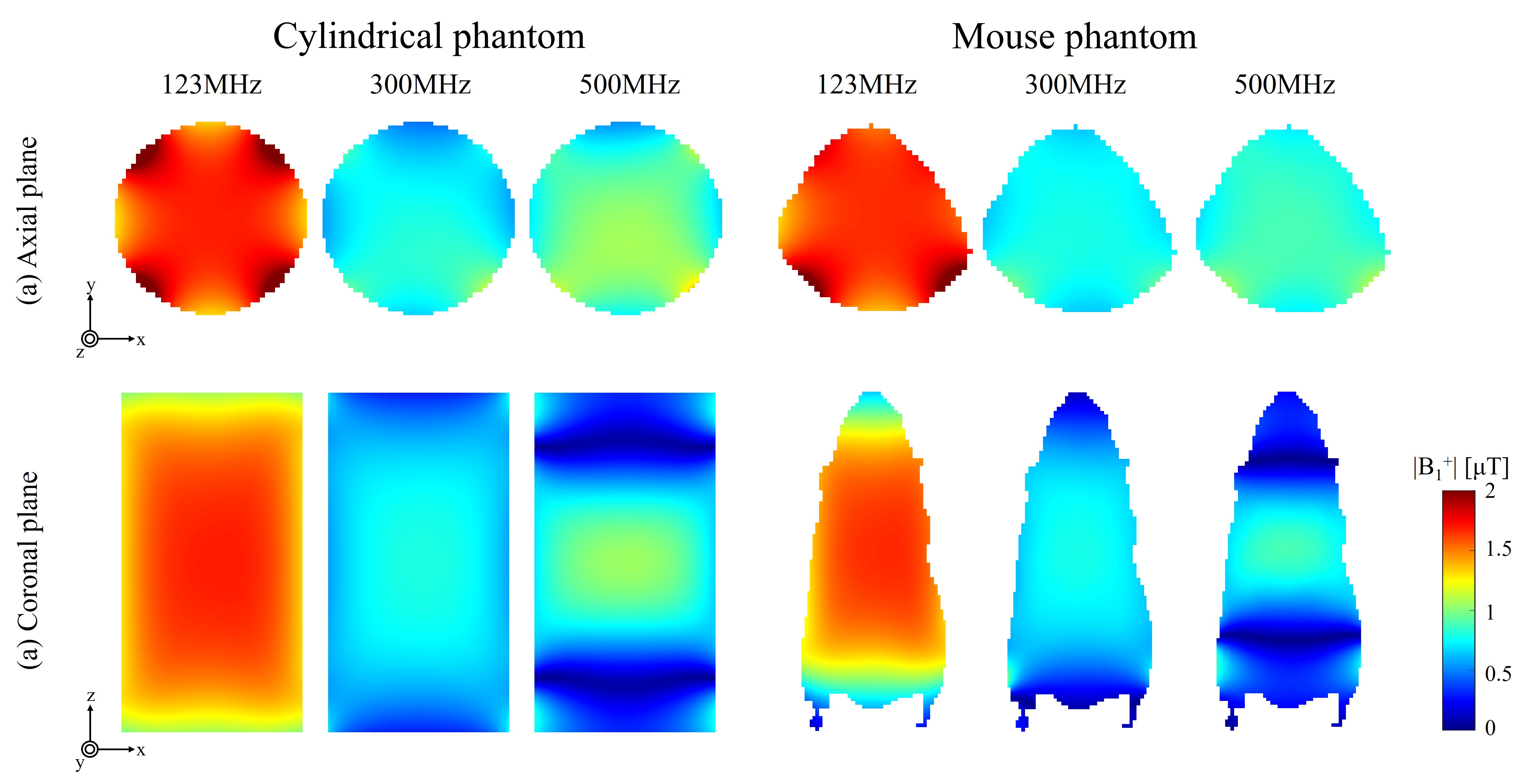
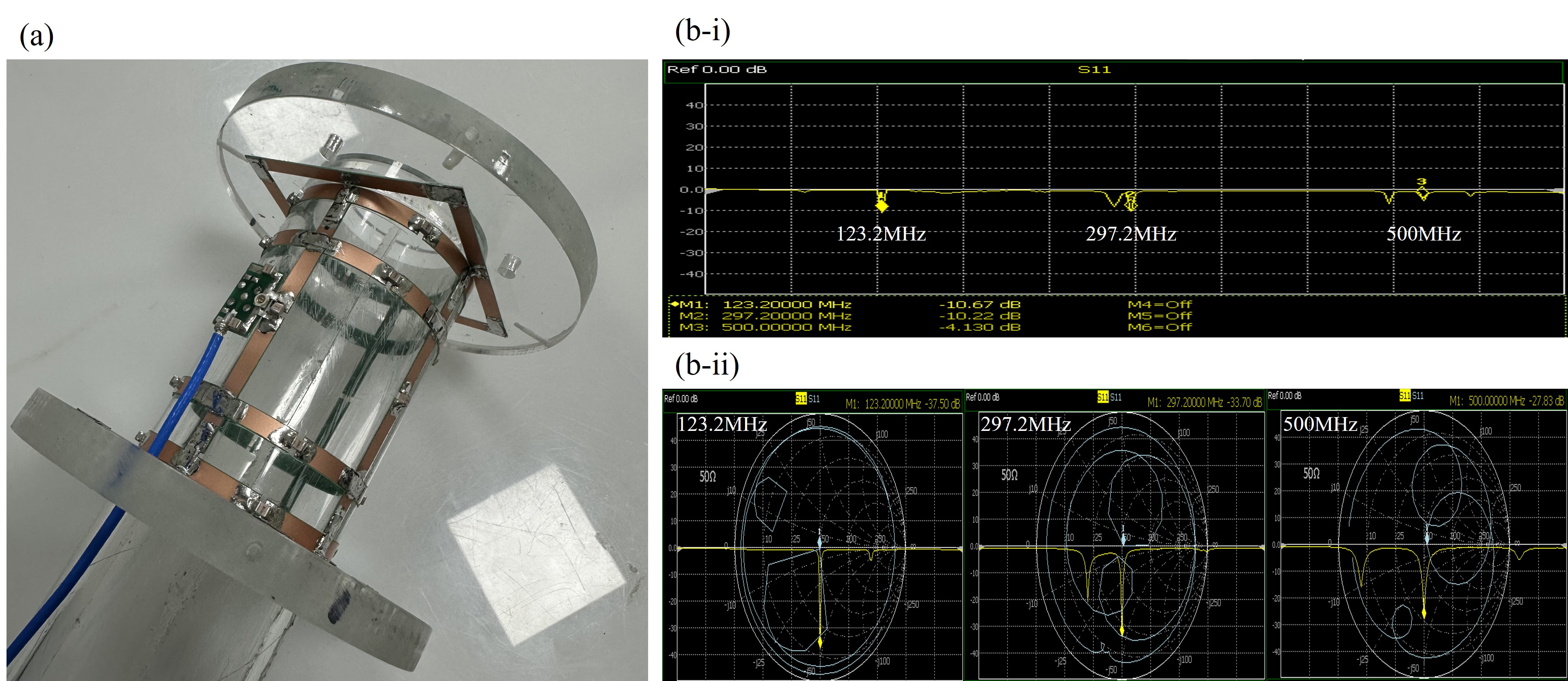
The TTBC is consist of two band-pass birdcage coils and a low-pass birdcage coil. In each configuration, the dominant modes were tuned to 123, 300 and 500MHz, and the corresponding capacitor values of capacitor on leg(CL), capacitor on inner end-ring(CIE) and capacitor on outer end-ring(COE) are summarized in Table.1. In the Table.2, the |B1+|-intensity and |B1+|-uniformity values according to change of DIO are summarized. In EM simulation, each configuration of TTBC showed more than 90% |B1+|-uniformity in central axial plane. However, when the DIO was less than 10mm, the TTBC suffered from severe |B1+|-intensity degradation at 500MHz. On the contrary, when the DIO was longer than 10mm, the |B1+|-intensity at 500MHz was higher than 300MHz. In the case of central coronal plane, the |B1+|-fields at 123 and 300MHz showed more than 72% |B1+|-uniformity. However, |B1+|-uniformity at 500MHz showed less than 64% in the mouse model. For 500MHz, TTBC with DIO of 15mm showed highest |B1+|-uniformity in central coronal plane. In addition, to secure an imaging area of 50mm or more, TTBC with DIO of 15mm was selected for manufacturing, and the corresponding |B1+|-field distribution is shown in Fig.2. The 16, 3.3 and 13pF of capacitors were used for legs, inner and outer end-rings, respectively. For the fine tuning, 2-10pF of variable capacitor was used for inner end-ring and 8-40pF of variable capacitors were used for leg and outer end-ring. The reflection coefficient(Sii) of the TTBC without applying the matching circuit for bench measurements is shown in Fig.3(b-i). When the matching circuit was applied(Fig.3(b-ii)), the Sii was -37.50, -33.70, and -27.83dB at 123.2, 297.2 and 500MHz, respectively.Discussion and Conclusion
In this study, we proposed a new configuration of birdcage coil for frequency selection in PET/MRI system. The TTBC, consisting of two squared stacked end-rings and four circular end-rings, can generate uniform |B1+|-field at triple resonance frequencies. The feasibility of TTBC was confirmed based on EM simulations and bench measurements. After designing and optimizing of additional circuitries, we plan to apply the TTBC to PET/MRI systems for 3T, 7T and 11.74T.Acknowledgements
This research was supported by the K-Brain Project of the National Research Foundation (NRF) funded by the Korean government (MSIT) (No. RS-2023-00264160)References
1. Seo M, Ko GB, Kim KY, et al. Performance evaluation of SimPET-L and SimPET-XL: MRI-compatible small-animal PET systems with rat-body imaging capability. EJNMMI Physics. 2023;10(1).
2. Hernandez D, Seo M, Han Y, Kim KN. Simulation-Driven Triple-Tuned Array for 1H, 31P and 23Na Using Composite Right- and Left-Handed Transmission Line for Rat Brain at 9.4T MRI. IEEE Access. 2022;10:104429-104435.
3. Han SD, Heo P, Kim HJ, et al. Double-layered dual-tuned RF coil using frequency-selectable PIN-diode control at 7-T MRI. Concepts in Magnetic Resonance Part B-magnetic Resonance Engineering. 2017;47B(4):e21363-e21363.
4. Hong SI, Wieland Alexander Worthoff, N. Jon Shah, Felder J. Design of a Folded, Double-Tuned Loop Coil for 1H/X-Nuclei MRI Applications. IEEE Transactions on Medical Imaging. 2023;42(5):1424-1430.
5. Ha Y, Choi CH, Worthoff WA, et al. Design and use of a folded four-ring double-tuned birdcage coil for rat brain sodium imaging at 9.4 T. Journal of Magnetic Resonance. 2018;286:110-114. 6. National Electrical Manufacturers Association. NEMA Standards Publication MS 3-2008: Determination of Image Uniformity in Diagnostic Magnetic Resonance images, 2008. Virginia, USA; 2008
Figures