1574
Designs of dielectric pad to improve B1 homogeneity and reduce SAR for the fetal imaging at 3T1Laboratory of Biophysics, School of Medicine, South China University of Technology, Guangzhou, China, 2Departments of Neurosurgery and Radiology, Pennsylvania State College of Medicine, Hershey, PA, United States
Synopsis
Keywords: Non-Array RF Coils, Antennas & Waveguides, Simulations, High Permittivity Materials, Fetal, RF shimming, Specific Absorption Rate
Motivation: Performing MRI on fetus at 3T can be clinically valuable but often encounters difficulties in transmit field inhomogeneity and SAR increase.
Goal(s): Determine dominant designing factors for optimal dielectric pad configurations to improve B1 homogeneity and reduce SAR for fetus imaging at 3T.
Approach: B1 field distributions of transmit body coil with dielectric pads of various designs in different positions around a pregnant woman model were evaluated using computer simulations.
Results: The placement of dielectric pad could significantly improve B1 field homogeneity (up to 84%) in the fetus brain. A generalizable routine can be developed for optimization of B1 shimming using dielectric pads.
Impact: Passive RF shimming with HPM is a viable ancillary approach for reduction of transmit field inhomogeneity artifacts for body imaging in high field MRI (≥3T), which affect the quality and safety of fetal MRI at 3T.
Introduction
$$$\quad\quad$$$While 3T MRI provides a greater image quality and faster scan time1, fetal MRI is predominantly conducted at 1.5T to avoid potential issues in increased Specific Absorption Rate (SAR) and transmission field inhomogeneity. To address these issue attempts have been made in utilization of high dielectric materials (HPM) to improve RF field inhomogeneity while simultaneously reducing SAR2-6. However, a systematic analysis of how the design and placement of dielectric pads affect the quality and safety of fetal MRI imaging at 3T remains lacking, which is the aim of this investigation.Method
$$$\quad\quad$$$All simulations were conducted using CST software with the 24-week pregnant virtual model, Katja7. Dielectric pads in different shapes and sizes and permittivity were placed on the back, at the side of waist, and above the stomach of the model. To assess the uniformity of the RF field, Relative Standard Deviation (RSD) was calculated as5: $$RSD=\frac{SD}{A}\times100\%$$where SD is the standard deviation of B1+, A is the mean of B1+ within ROI. The simulation conducted without the dielectric pad was served as the baseline. All simulated values were compared to the baseline and normalized by the average B1+ in the ROI for comparisons.Result
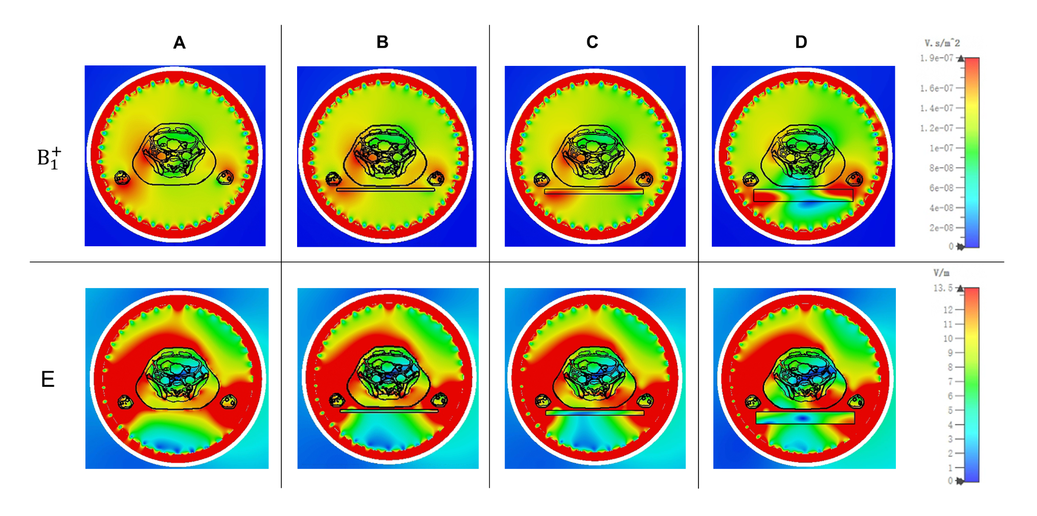
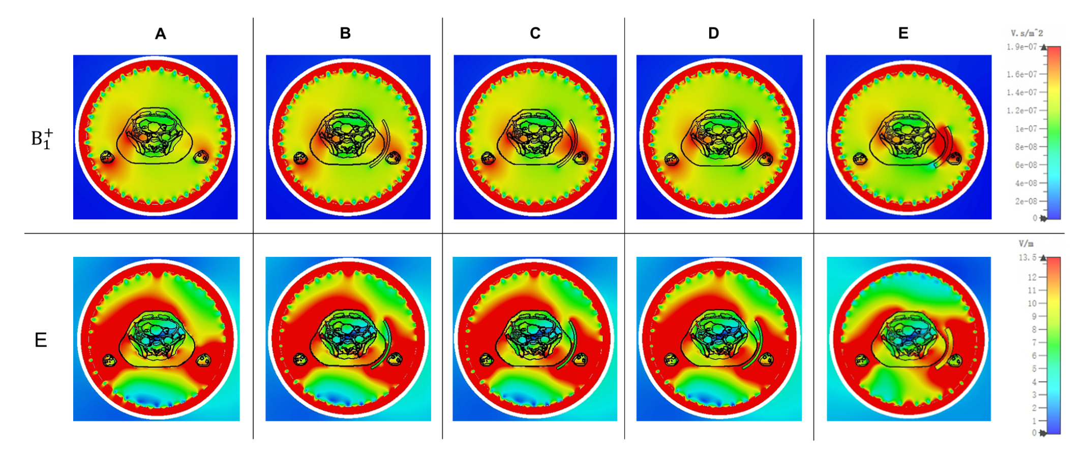
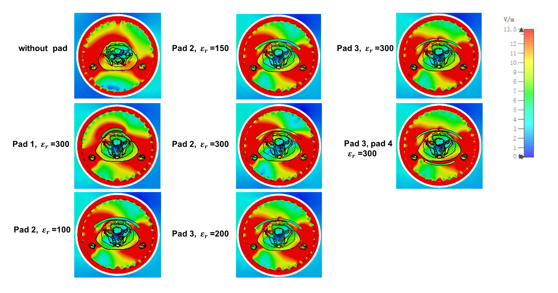
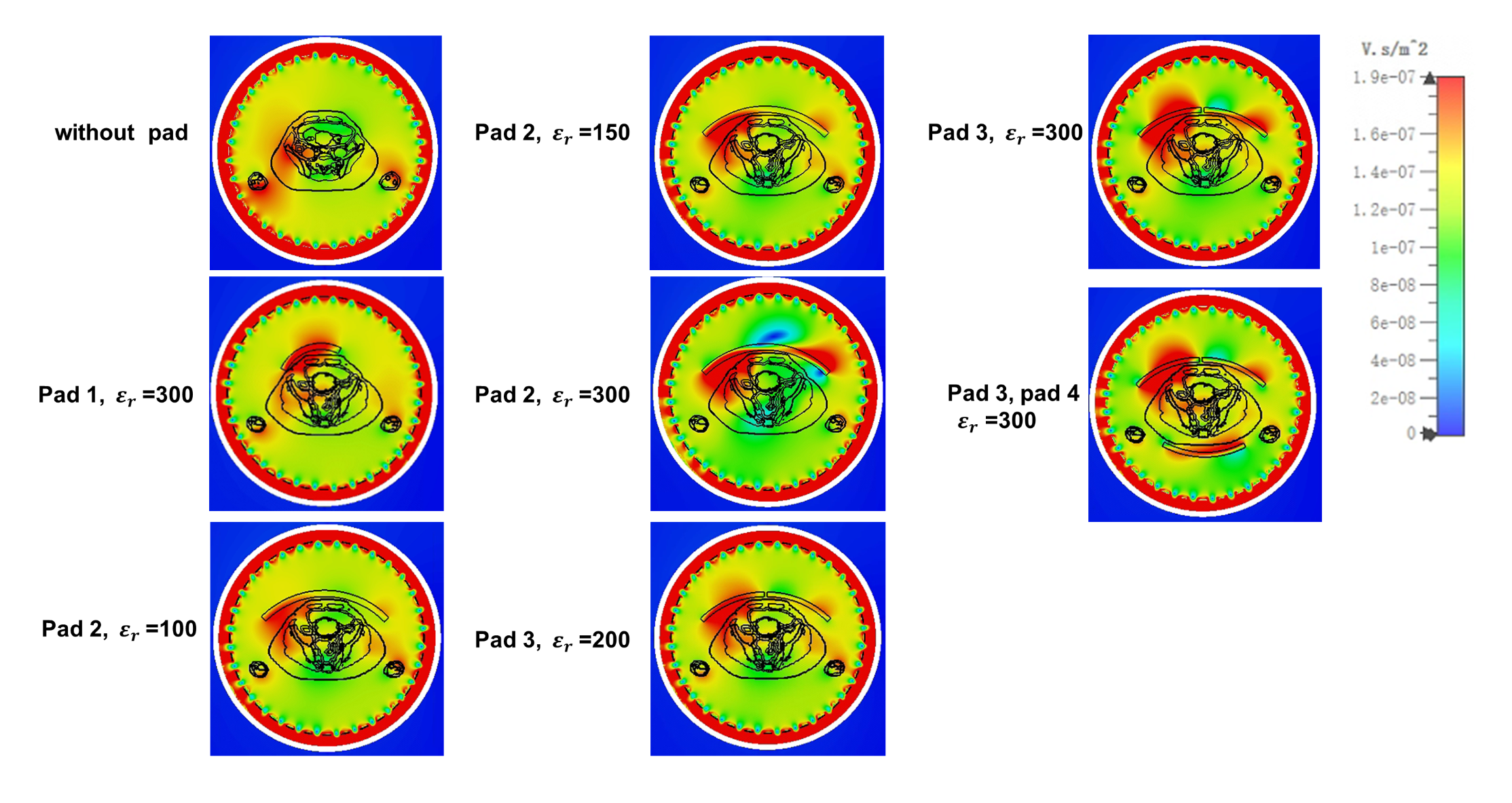
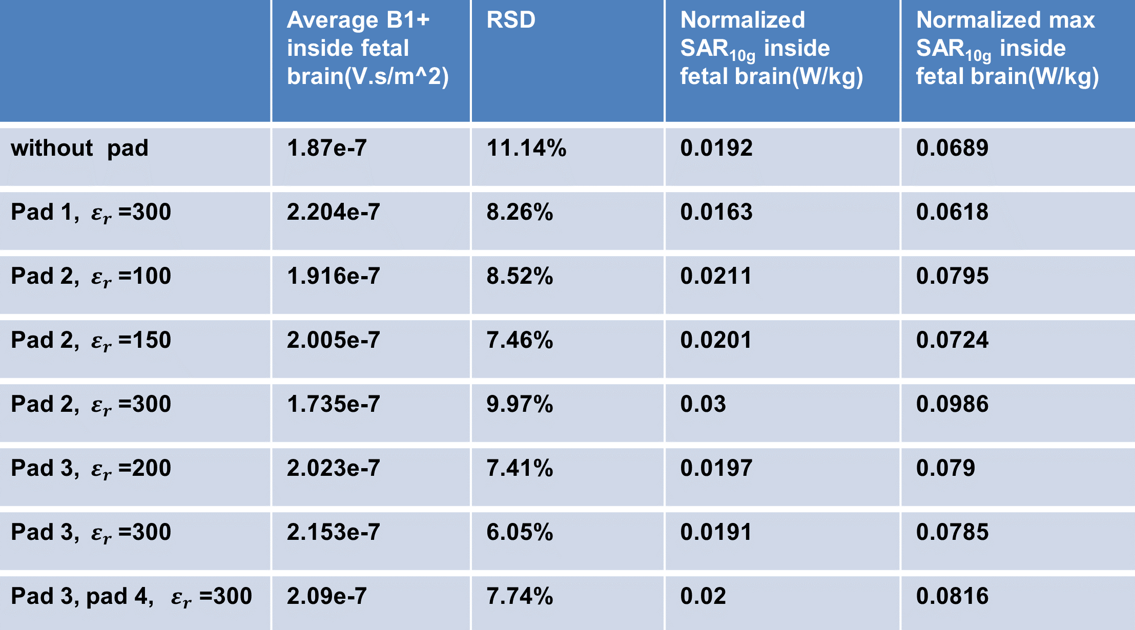
$$$\quad\quad$$$Figure 1 illustrates the strong influences of B1+ and E field distribution with the dielectric pad positioned on the back for the human model. Varying the thickness of the dielectric pad in this case, however, did not alter the RF field in the fetal brain. Similarly, a dielectric pad conformal to the side of her body (Figure 2), did not improve the inhomogeneity of RF field within the fetal brain, although changed the RF field strongly in the vicinity.$$$\quad\quad$$$Figures 3 and 4 show the E and B1+ field distribution when different dielectric pads were placed on the stomach of Katja, respectively. For all cases for this configuration, significant improvements in RF field uniformity were observed. As indicated in the Table 1, Pad 1 and Pad 3 ($$$\varepsilon_{r}=300$$$) improved the RSD to 35% and 84% within the fetal brain, respectively, with no increase of SAR.
Discussion
$$$\quad\quad$$$Although the modern 3T systems are usually equipped with dual transmit RF coil system, which allow for adjust RF field homogeneity in given ROIs for general clinical applications, it is ineffective for some special case such as fetal imaging at later stage for pregnancy. Thus, passive RF shimming with HPM remains a viable ancillary approach for increasing the utilization of high field MRI (≥3T). In addition, proper placement of HPM can also effectively reduces the over RF transmission power and local SAR, which is particularly important for the safety for imaging of fetus.$$$\quad\quad$$$Although only limited HPM pad configurations were examined in this study, we demonstrated that the overall homogeneity RF transmission field in the targeted ROI can be improved significantly (up to 84%) and that further systematic investigation is needed to evaluate how the HPM pads can be best used for the pregnant woman at various gestation stage and fetal positions in combination with active RF shimming. In addition, it has been demonstrated that HPM can also be used with receive array coils for enhancing SNR. Thus, it is possible to integrate HPM into RF coil design to improve performances of both transmission and reception coils. With recent advances in material development, the permittivity range of HPM can be achieved from a few hundred to several thousands, which provides the necessary flexibility for passive shimming of RF field with HPM.
Conclusion
$$$\quad\quad$$$Placing dielectric pad can significantly alter the overall RF transmission field and SAR distributions. A systematic study is underway for developing an automatic passive shimming routine for general clinical applications.Acknowledgements
This study was partially supported by the National Natural Science Foundation of China (No. 61929101, 61671229), National Key Research and Development Program of China (No. 2016YFC0100800, 2016YFC0100801), Science and Technology Program of Guangzhou, China (No.201704020091), and Science and Technology Program of Guangdong, China (No. 2017B020229004).References
1. Nagaraj, Usha D., et al. Utilization of 3-T fetal magnetic resonance imaging in clinical practice: a single-institution experience. Pediatric Radiology. 2021;51(10):1798-1808.
2. Yang, Qing X., et al. Reducing SAR and enhancing cerebral signal‐to‐noise ratio with high permittivity padding at 3 T. Magnetic resonance in medicine. 2011;65(2):358-362.
3. Brink, Wyger M., Johan S. van den Brink, and Andrew G. Webb. The effect of high-permittivity pads on specific absorption rate in radiofrequency-shimmed dual-transmit cardiovascular magnetic resonance at 3T. Journal of Cardiovascular Magnetic Resonance. 2015;17(1):1-8.
4. Koolstra, Kirsten, et al. Improved image quality and reduced power deposition in the spine at 3 T using extremely high permittivity materials. Magnetic resonance in medicine. 2018;79(2):1192-1199.
5. Luo M, Hu C, Zhuang Y, et al. Numerical assessment of the reduction of specific absorption rate by adding high dielectric materials for fetus MRI at 3 T. Biomedical Engineering / Biomedizinische Technik. 2016;61(4):455-461.
6. van Gemert J, Brink W, Remis R, et al. A simulation study on the effect of optimized high permittivity materials on fetal imaging at 3T. Magnetic resonance in medicine. 2019;82(5):1822-1831.
7. Becker J, Zankl M, Fill U, et al. Katja—the 24 week of virtual pregnancy for dosimetric calculations. Polish Journal of Medical Physics and Engineering. 2008;14(1):13-20.
Figures