1573
A Simulation-based Study of the Cycloid Dipole as an RF Coil Element for 7T MRI1Kuwait University, Kuwait, Kuwait, 2Department of Biomedical Engineering, Texas A&M University, College Station, TX, United States, 3Department of Electrical and Computer Engineering, Texas A&M University, College Station, TX, United States
Synopsis
Keywords: Non-Array RF Coils, Antennas & Waveguides, Non-Array RF Coils, Antennas & Waveguides
Motivation: The demand for improving RF coil designs to maximize the potential of high-field MRI continues to grow. Exploring innovative RF coil elements holds the potential to improve RF coil performance and diagnostic image quality.
Goal(s): Our goal is to investigate the performance of a cycloid dipole antenna as a possible RF coil element for high-field MRI.
Approach: FDTD simulations were performed to compare the performance of a standard half-wavelength dipole at 7 T with two variations of the cycloid dipole.
Results: Cycloid dipole exhibits a shorter resonance structure, higher B1+ and B1+/√SAR10g_max efficiencies when compared to the standard dipole antenna.
Impact: The study introduces cycloid dipoles as potential MRI coil elements. This opens opportunities for future investigations to optimize cycloid antennas within specific MRI coil designs, improving clinical imaging quality.
Introduction:
The half-wavelength dipole has a significant presence as an RF coil element for high-field magnetic resonance imaging (MRI)[1, 2] as it provides a high penetration depth and a relatively uniform and symmetric transmit field [3]. Many researchers are investigating modifications of the standard dipole for application in high-field MRI. Among these are the bent dipole [4], the bumped dipole [5], the meander dipole [6], and dipoles with high dielectric material [7]. These can achieve improved SAR efficiency and shorter effective lengths than the standard dipole. One dipole variation that has not been examined is the so-called “cycloid” dipole, a hybrid loop-dipole. Though there is little formal literature [8], this element is included in the MATLAB Antenna toolbox [9]. Here we investigate this element as a possible element for high-field MR.Methods:
To investigate the performance of the cycloid dipole as an RF coil element at 7T, three dipole antennas were simulated. A standard half-wavelength dipole (Figure 1A) served as the baseline, while two variations of cycloid dipoles (Figure 1B and Figure 1C) were simulated for comparative analysis: standard cycloid dipole, characterized vertical linear segment and horizontal loop, and the twisted cycloid dipole featuring a twisted loop adjusted to a vertical orientation while retaining the linear segment. A commercial FDTD simulation software (XFdtd 7.4, Remcom, State College, PA, USA) was employed alongside MATLAB (The Mathworks, Inc., Natick, MA, USA) for data processing during the simulations. A rectangular block phantom with very approximate body equivalent dielectric properties [10] was modeled away from the dipoles. With the aim of tuning the dipoles to 298 MHz, geometrical adjustments were made: the standard half-wavelength dipole was optimized to a length of 42 cm, the cycloid dipoles were designed to be 36 cm long, featuring a 5 cm diameter loop segments. The conductive material was modeled aswide PEC, all dipoles were excited using , source through 1 cm feed gap.Results:
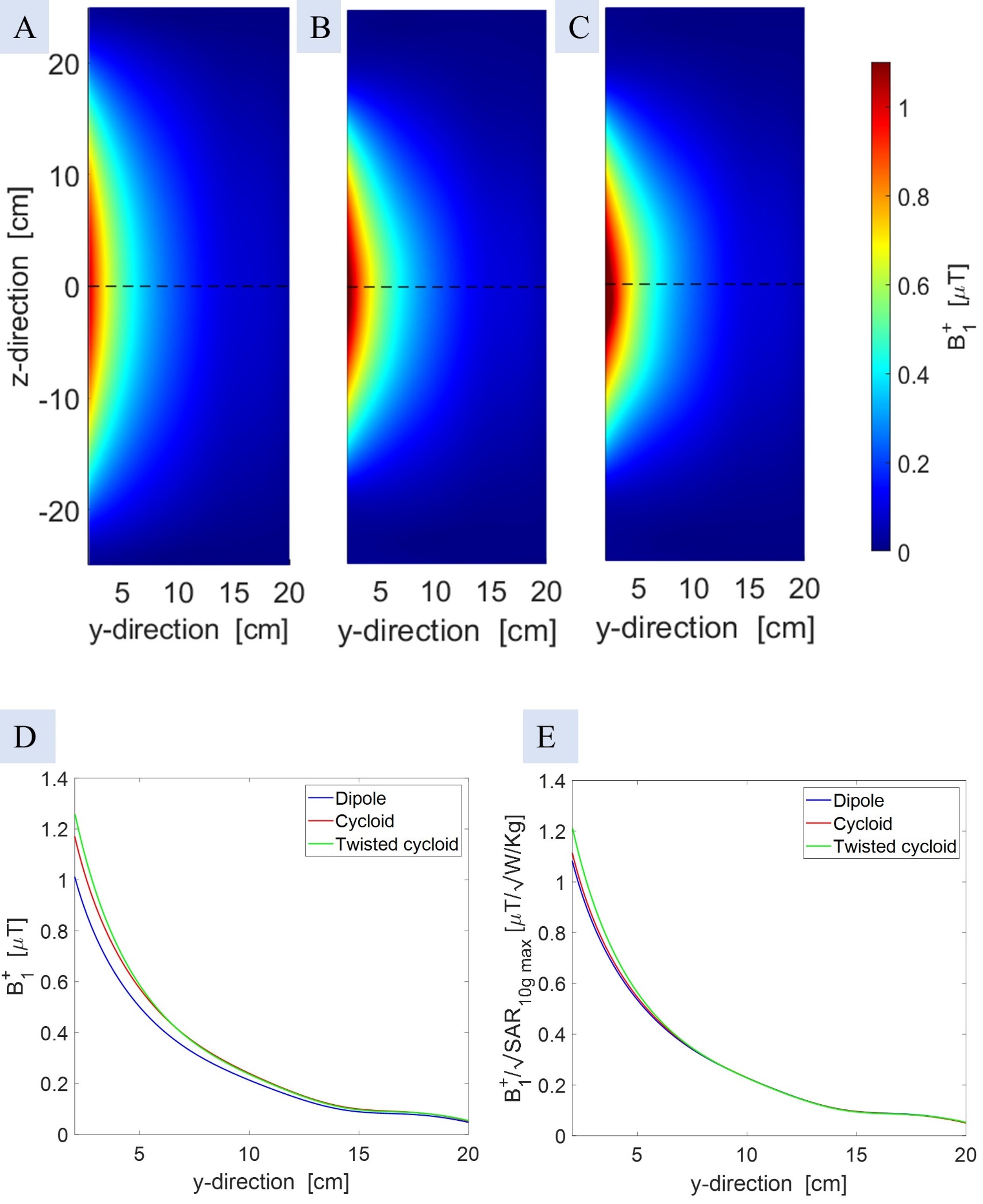
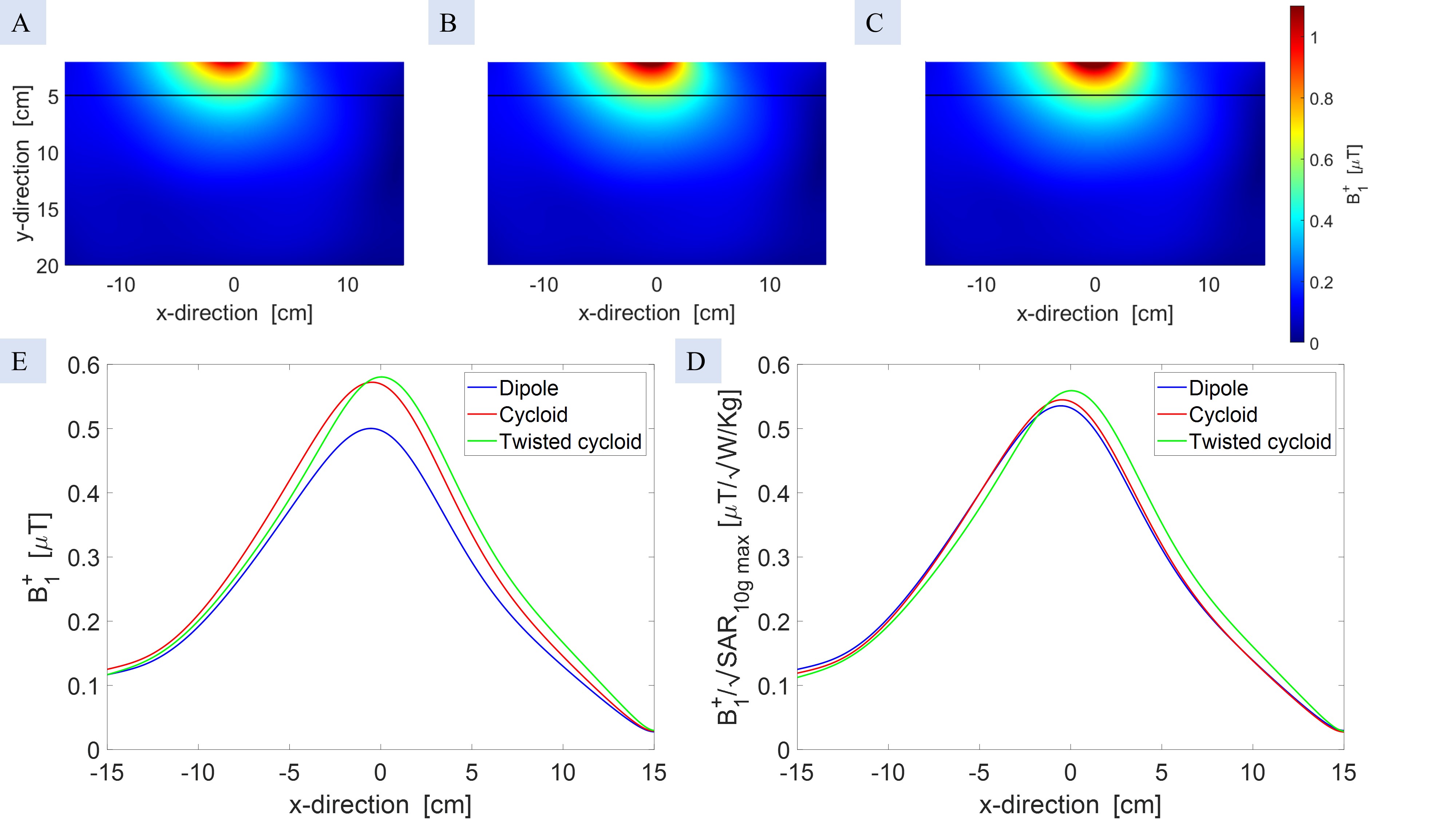
In Figures 2 and 3, B₁⁺ maps representing transverse and sagittal planes are displayed in the three simulated antennas, each normalized to 1 W input power. The maps illustrate anticipated narrower sagittal fields for the cycloid dipole elements, attributed to the reduction in the antenna length along the z-axis. Analysis of B₁⁺ efficiency profiles, as represented in (Figure 2D), demonstrates the superior performance of both cycloid dipoles over the standard dipole. Notably, the twisted dipole excels over the standard cycloid, showcasing higher B₁⁺ efficiency up to 6 cm into the phantom, after which both cycloids display comparable efficiency, both outperforming the standard dipole. A similar trend is noted in Figure 3D. However, a slight variation is observed in the pattern when comparing the standard cycloid to the twisted cycloid. The simulated maximum SAR10g was measured as 0.8726, 1.103, and 1.078 W/Kg for the standard dipole, standard cycloid, and twisted cycloid respectively. Despite elevated maximum SAR10g values in the cycloid dipoles, the B₁⁺ /√SAR10g_max profiles in (Figure 2E and Figure 3E) illustrate their superiority over the standard dipole in efficiency.Discussion and Conclusion:
This study investigated the performance of cycloid dipole antenna as an RF coil element for 7 T MRI. The introduction of the twisted cycloid variant was intended to explore the impact of the loop's orientation while seeking the added benefit of reducing the depth of the cycloid dipole. This alteration aims to enable a more practical integration into a variety of MRI coil setups, such as those requiring compact dimensions. The results presented in this study indicate superior B₁⁺ efficiency for the cycloid dipoles, notably the difference in the profile and efficiency between the two cycloids, indicates that the loop's purpose extends beyond shortening the dipole antenna, contributing to improved field penetration and B₁⁺ efficiency. Further refinement and optimization of the linear segment and loop dimensions of the cycloid dipoles are essential to ensure optimal performance and compatibility within specific MRI coil designs. This initial investigation presents a promising direction for future studies to refine the cycloid antenna design, enabling its integration into standard MRI coil configurations.Acknowledgements
No acknowledgement found.References
[1]G. Solomakha, D. Bosch, K. Scheffler, and N. Avdievich, "Evaluation of Coaxial Dipole Antennas as "Transceiver Elements of Human Head Array for Ultra-High Field MRI at 9.4 T," 2023.
[2]J. K. Stelter, M. E. Ladd, and T. M. Fiedler, "Numerical comparison of local transceiver arrays of fractionated dipoles and microstrip antennas for body imaging at 7 T," NMR in Biomedicine, vol. 35, no. 8, p. e4722, 2022.
[3] A. J. E. Raaijmakers et al., "Design of a radiative surface coil array element at 7 T: The single-side adapted dipole antenna," Magnetic Resonance in Medicine, vol. 66, no. 5, pp. 1488-1497, 2011, doi: https://doi.org/10.1002/mrm.22886.
[4] N. I. Avdievich, G. Solomakha, L. Ruhm, J. Bause, K. Scheffler, and A. Henning, "Bent folded‐end dipole head array for ultrahigh‐field MRI turns “dielectric resonance” from an enemy to a friend," Magnetic resonance in medicine, vol. 84, no. 6, pp. 3453-3467, 2020.
[5] A. Sadeghi-Tarakameh et al., "Improving radiofrequency power and specific absorption rate management with bumped transmit elements in ultra-high field MRI," Magnetic Resonance in Medicine, vol. 84, no. 6, pp. 3485-3493, 2020, doi: https://doi.org/10.1002/mrm.28382.
[6] I. Zivkovic, C. A. de Castro, and A. Webb, "Design and characterization of an eight-element passively fed meander-dipole array with improved specific absorption rate efficiency for 7 T body imaging," NMR in Biomedicine, vol. 32, no. 8, p. e4106, 2019, doi: https://doi.org/10.1002/nbm.4106.
[7] A. A. Bhosale, D. Gawande, and X. Zhang, "B1 field flattening and length control of half-wave dipole antenna with discrete dielectric coating," in Proceedings of the International Society for Magnetic Resonance in Medicine... Scientific Meeting and Exhibition. International Society for Magnetic Resonance in Medicine. Scientific Meeting and Exhibition, 2022, vol. 30: NIH Public Access.
[8] T. Abbott. "A very quick look at WA7X cycloid antenna." http://www.wa7x.com/cycloid_info.html (accessed 4. Nov 2023).
[9] I. The MathWorks. "Antenna Toolbox." https://www.mathworks.com/help/antenna/ref/dipolecycloid.html (accessed 5. Nov 2023).
[10] B. van den
Bergen, C. A. T. van den Berg, D. W. J. Klomp, and J. J. W. Lagendijk,
"SAR and power implications of different RF shimming strategies in the
pelvis for 7T MRI," Journal of Magnetic Resonance Imaging, vol. 30, no. 1,
pp. 194-202, 2009, doi: https://doi.org/10.1002/jmri.21806.
Figures