1571
Enabling Wide-Area Imaging in MR Microscopy with a Double Helix Dipole Coil1Graduate School of Science and Technology, University of Tsukuba, Tsukuba, Japan
Synopsis
Keywords: Non-Array RF Coils, Antennas & Waveguides, Non-Array RF Coils, Antennas & Waveguides
Motivation: The DHD coil in the previous study had a narrow sensitivity region. We developed a DHD coil with improved sensitivity region and B1 uniformity to image large samples while maintaining SNR.
Goal(s): Imaging of all organs, especially the brain of a human embryo, using a coil with a wider sensitivity region.
Approach: We performed electromagnetic field simulations to find the shape that would give the best performance, and fabricated the coil.
Results: The imageable area was widened by 30% and the insensitive area was reduced. Not only the brain of a human embryo, but also organs could be imaged at the same time.
Impact: The DHD coil's geometry was determined by electromagnetic field simulation, which allows a 30% wider range in the z-axis than conventional coils. The human embryonic brain and organs such as the heart could be simultaneously imaged with sufficient SNR.
Introduction
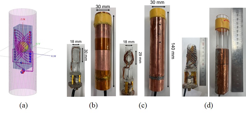
Saddle and birdcage coils have a low signal-to-noise ratio (SNR) and are not suitable for MR microscopy. Double helix design (DHD) RF coils are combination of two inclined solenoid coils as shown in figure 1(a) and has been shown to have a higher SNR than the saddle coil and demonstrated only for low-field MRI1.We then proposed a prototype DHD RF coil for 7T MRI with appropriate coil splitting to accommodate higher frequencies2. In this study, we optimized the geometry of the RF DHD coil and experimentally validated an improved DHD coil that can image a wider field of view while maintaining a high SNR.Method
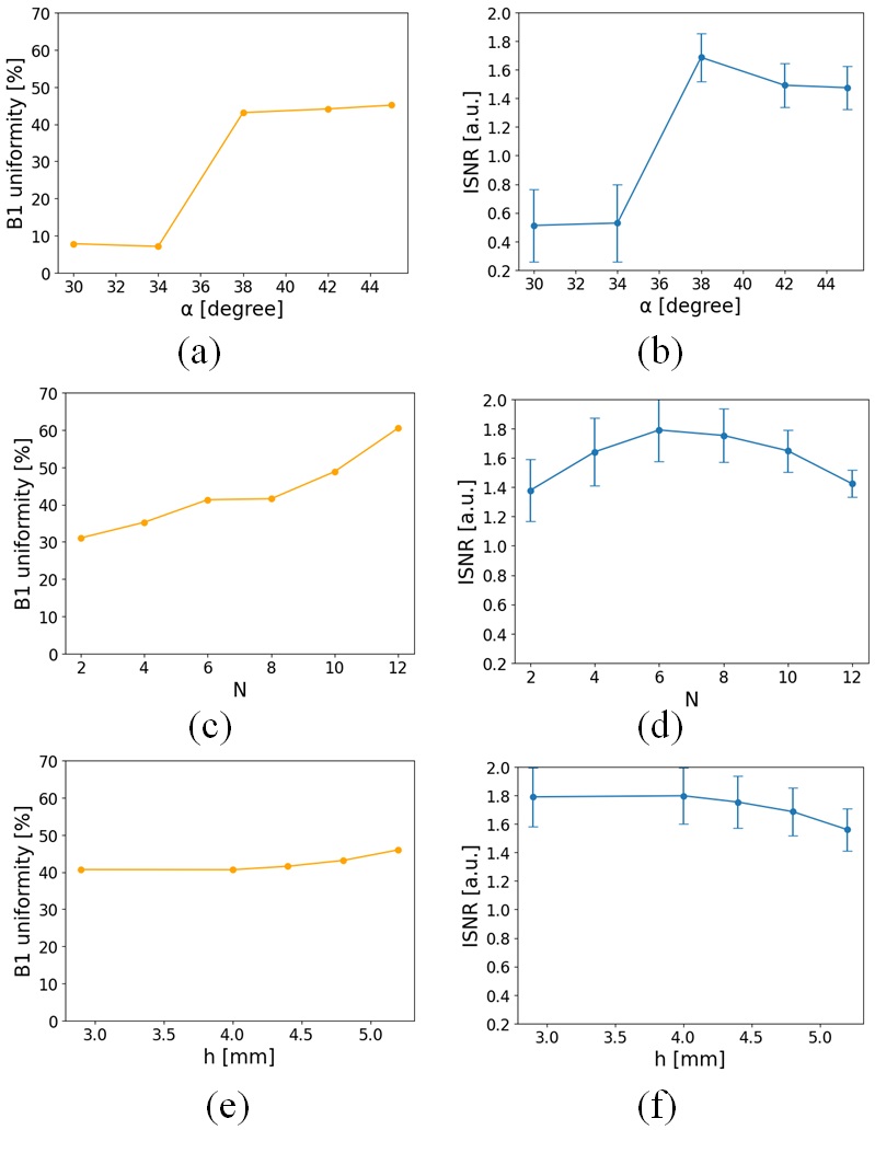
SimulationThe pitch spacing h, the winding angle α, and the number of coils N were used as parameters of the geometry. The electromagnetic field calculation software FEKO (www.feko.info) was used to calculate the intrinsic SNR (ISNR) and the B1 distribution. The diameter was 18 mm and the height was 44 mm(h=4.4 mm, α=38° and N=10). The calculation area was 4.608 × 1.5362 cm3 and the matrix size was 384 × 1282. The target volume was set at a 12 mm sphere. The B1 uniformity was defined as the percentage of deviation from the average B1 intensity within 5% in the target volume. The ISNR was the average value within the target volume normalized by the value of the saddle coil. We focused on the values of B1 uniformity and ISNR to determine the geometry.
Experiment
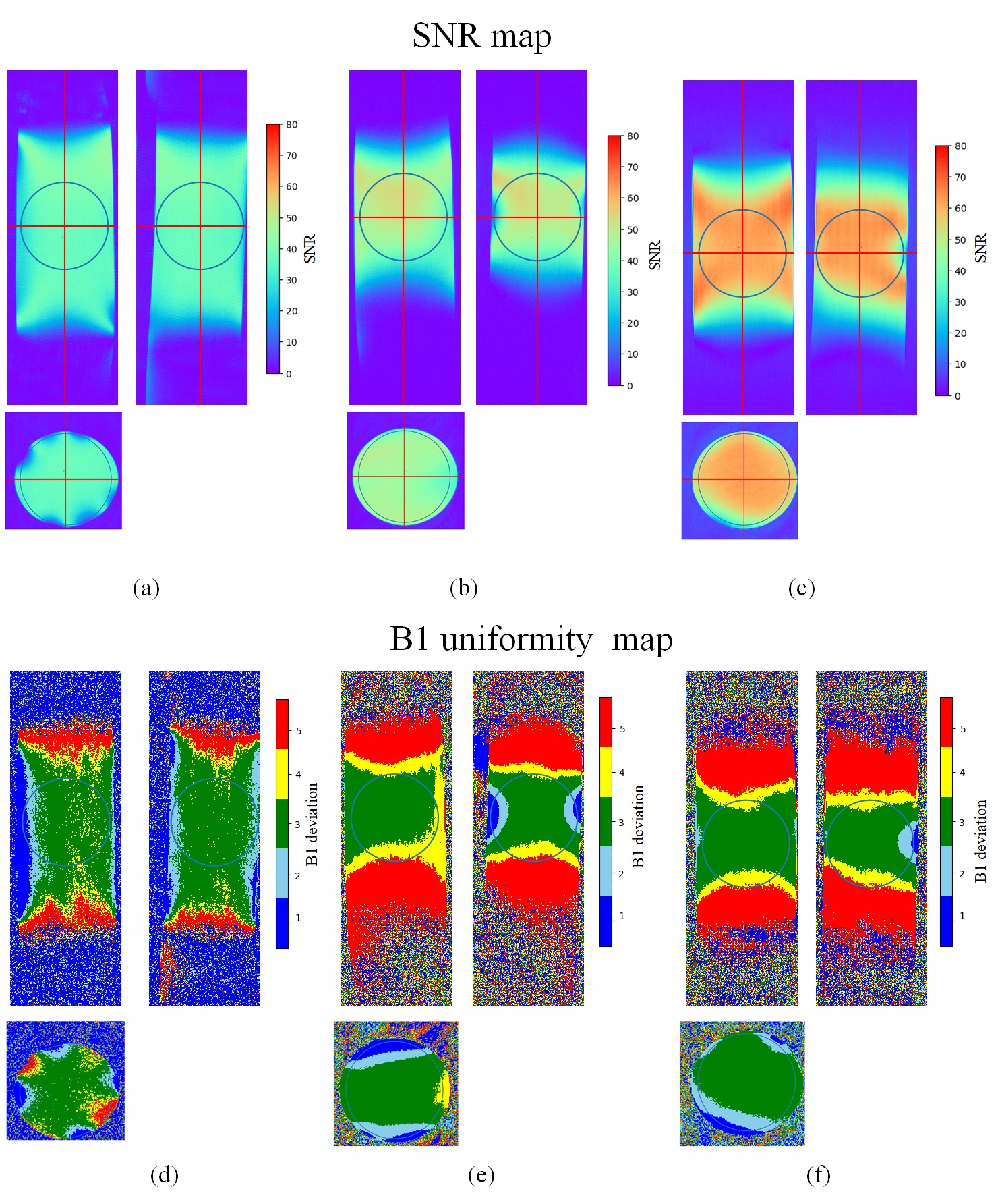
RF coils with shapes optimized by simulation were constructed and used for experimental validation. The DHD coil was divided into 20 sections with a 6.2 pF chip capacitor in the loop section to achieve 301.5 MHz. A cylindrical shield box with a diameter of 30 mm and a height of 59 mm was fabricated wound with 0.1 mm thick copper foil. Baby oil containing mineral oil and tocopherol acetate (Johnson's) and a human embryo specimen at Carnegie stage 23 preserved in 10% formalin were each placed in a 15 mm outer diameter NMR tube. A double flip angle method with a gradient echo sequence was used for measuring B1 uniformity3. The FOV was 4.608 ×1.5362 cm3, the voxel size was (120 µm)3, and TR/TE=1200/6 ms. Here, FA was 60° and 120°. The number of excitations (NEX) was 1. For SNR measurements, we used the spin echo method for baby oil with TR/TE set to 400/10 ms. For human embryo, the gradient echo method was used with a voxel size of (60 µm)3, TR/TE of 400/4.6 ms, FA was 90°, NEX of 1.
Results
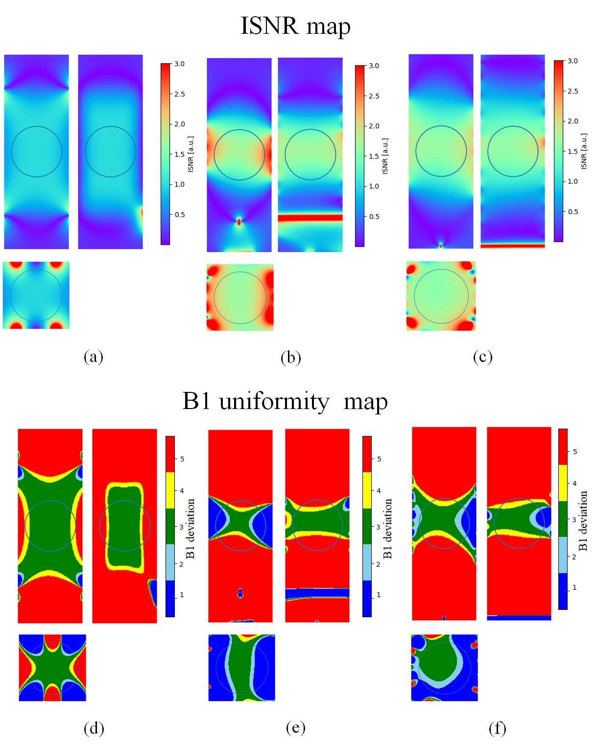
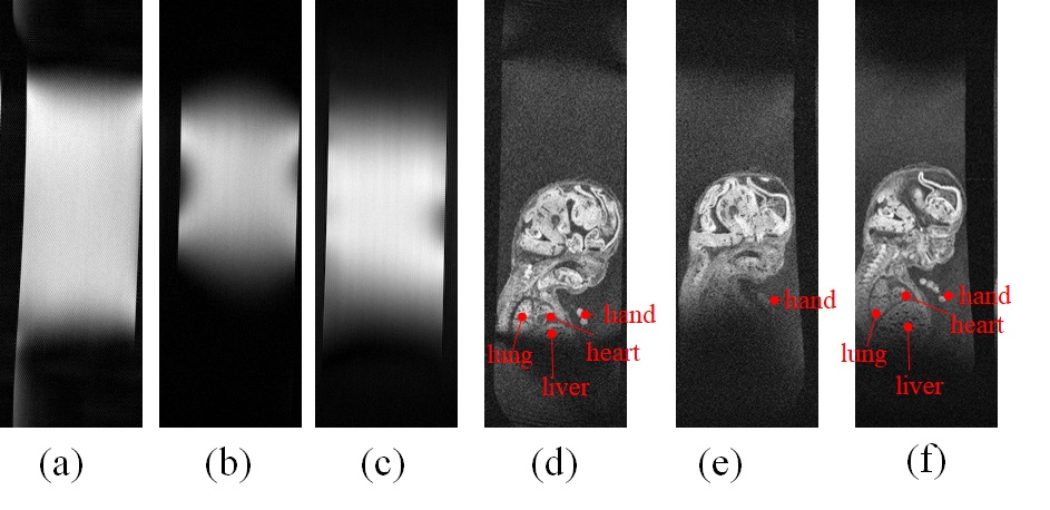
Figures 1(b,c) show the DHD coil (h = 3.9 mm, α = 45°, and N = 6) and the saddle coil (1 loop, the opening angle was 120°) used in the previous study2. Figure 1(d) shows the newly created DHD coil (h = 4.4 mm, α = 38°, and N = 10).In Figures 2(a,b), with fixed values of N=8 and h=4.8, the B1 uniformity and the ISNR increases at α = 38°. In Figures 2(c,d), the B1 uniformity monotonically increases with N. However, we set N=10, as exceeding N=12 would result in overlap between the upper and lower parts of the coil windings (α = 38°, h = 4.4). In Figures 2(e,f), the B1 uniformity increases monotonically, while the ISNR decreases monotonically with respect to h. Therefore, h = 4.4 mm was selected to avoid overlap as well as N(α = 38°, N=10).The B1 uniformity and the ISNR of a 10-turn DHD coil were 48% and 1.64 respectively, compared with 40% and 1.73 for a 6-turn DHD coil.Figure 3 shows the ISNR map and B1 uniformity map obtained by simulation for each coil. In Figure 4, the B1 uniformity and SNR for the 10-turn DHD coil were 46% and 59.7, respectively, while those for the 6-turn DHD coil were 45%,46.5. The 10-turn DHD coil had a 30% wider region in the z-axis direction than the 6-turn DHD coil, while satisfying Rose's criterion (SNR>4)4. As shown in Figure 5(d,f), the saddle coil and the newly developed 10-turn DHD coil can simultaneously depict the lung, heart, and liver.Discussion
The geometry parameter α is optimal at 38° for B1 uniformity according to Biot-Savart's law1. The values of N and h were limited by the coil overlap, but by choosing the maximum B1 uniformity, a 30% wider area could be imaged in the z-axis.The developed DHD coil which has a wider image area, are useful for imaging samples that are longitudinal and cannot be cut, such as human embryos.Acknowledgements
No acknowledgement found.References
1. Alonso J, Soleilhavoup A, Wong A, Guiga A, Sakellariou D. Double helix dipole design applied to magnetic resonance: a novel NMR coil. J Magn Reson 2013; 235:32–41.
2. Yuto Murakami and Yasuhiko Terada.Development of a multi-turn double helix dipole coil for magnetic resonance microimaging of chemically-fixed human embryos at 7T.15-20 May 2021, ISMRM & SMRT Annual Meeting & Exhibition. (2514)
3. E. K. Insko, L. Bolinger, Mapping of the Radiofrequency Field, Journal of Magnetic Resonance 103, 82-85 (1993)
4. Rose A. Vision: human and electronic. (Optical physics and engineering.) New York: Plenum; 1973
Figures