1570
High Temperature Superconducting (HTS) Multi Loop Transmission Line Resonator for Magnetic Resonance Imaging1Université Paris-Saclay, Laboratoire Biomaps, ORSAY, France, Metropolitan, 2Thales Research & Technology, Palaiseau, France, Metropolitan, 3Université Paris-Saclay, CEA, NeuroSpin, Gif-sur-Yvette, France, Metropolitan, 4GEPI – Observatoire de Paris, Université PSL, Paris, France, Metropolitan, 5Unité Mixte de Physique, CNRS, Thales, Université Paris-Saclay, Palaiseau, France, Metropolitan
Synopsis
Keywords: Non-Array RF Coils, Antennas & Waveguides, Non-Array RF Coils, Antennas & Waveguides, High Temperature Superconductor
Motivation: Multi-Loop Coils (MLCs) allow to reduce the sample-induced noise while achieving a large Field Of View. Their sensitivity would be improved with the use of superconducting materials.
Goal(s): We aim to develop a superconducting MLC achieving both a large Field Of View and high quality factor.
Approach: An initial design is modified to render a MLC self-resonant and optimized using electromagnetic simulations.
Results: The HTS Multi Loop Transmission Line Resonator coil characterizations are presented. Q-factor and resonance frequency decline in presence of the static magnetic field or of a conductive sample but the coil still exhibits higher performances than copper MLCs.
Impact: Multi Loop Transmission Line Resonator represents a promising design strategy to increase the Field Of View of HTS reception coils without compromising with the coil sensitivity.
Purpose
High-temperature superconducting (HTS) surface coils for Magnetic Resonance Imaging (MRI) have been studied for decades and their interest is well established [1]. Their use is only relevant if the coil-noise is the dominant noise source. This condition sets a maximum coil diameter and therefore a limited Field Of View (FOV) which reduces their applicability. In this context, the development of HTS coils arrays to achieve an extended FOV, calls for small-sized elements operated in parallel and poses strong challenges for mutual elements decoupling [2] since standard strategies, using lumped elements are inappropriate. Multi-Loop Coil (MLC) design [3] allows to reduce the sample-induced noise while achieving a large FOV and, by nature, avoids peak-splitting induced by inductive coupling between loops as they are operated in series. Up to now, MLCs have been designed using the standard coil principle based on discrete components for tuning and matching. In order to avoid discrete components and preserve their quality factor, HTS coils must be based on self-resonant principles, such as transmission line design [4]. To develop a monolithic version of an MLC matching the requirements of superconducting coils, the original design has to be modified to render the MCL self-resonant. Using design optimization by electromagnetic simulations a HTS Multi Loop Transmission Line Resonator (MLTLR) for proton MRI at 3 T is manufactured [5]. It is characterized on a bench and in imaging conditions : the impact of cooling conditions and of a conductive sample on the resonance frequency and Q-factor are studied.Methods
The initial 19-loop design [3] has been modified as proposed by Dubuc et al. [5]. Designs have been evaluated and simulated using a finite element method solver (HFSS Ansys). The number of gaps (2 opposite gaps per side) and final size of the coil (41 mm outer diameter) were chosen so that the resonance frequency $$$f_0$$$ is close to 127.73 MHz (Larmor frequency at 3T). The HTS MLTLR has thus 19 loops of diameter 6.74 mm and 0.66 mm width etched on a 330 μm thick sapphire (r-cut) substrate as shown on fig.1. Bench characterizations of the HTS MLTLR were performed in liquid nitrogen (LN2). Q-factor and $$$f_0$$$ measurements were systematically performed using $$$S_{21}$$$-parameters in field (coil cooled inside the static field) or zero-field(coil cooled in the Earth field) cooling conditions as in [6]. To study the effect of the static field, the cooled coil was oriented so that the substrate plane was parallel to $$$B_0$$$ field and placed either in the bore or in the fringe field of a 3 T GE Signa MRI magnet, so as to produce static field amplitudes ranging from the Earth’s field to 3 T. The field strength was measured using a Hall effect probe (F.W. Bell Hand-Held Gauss/Tesla Meter Model 4048with axial probe A-4048-002).Results
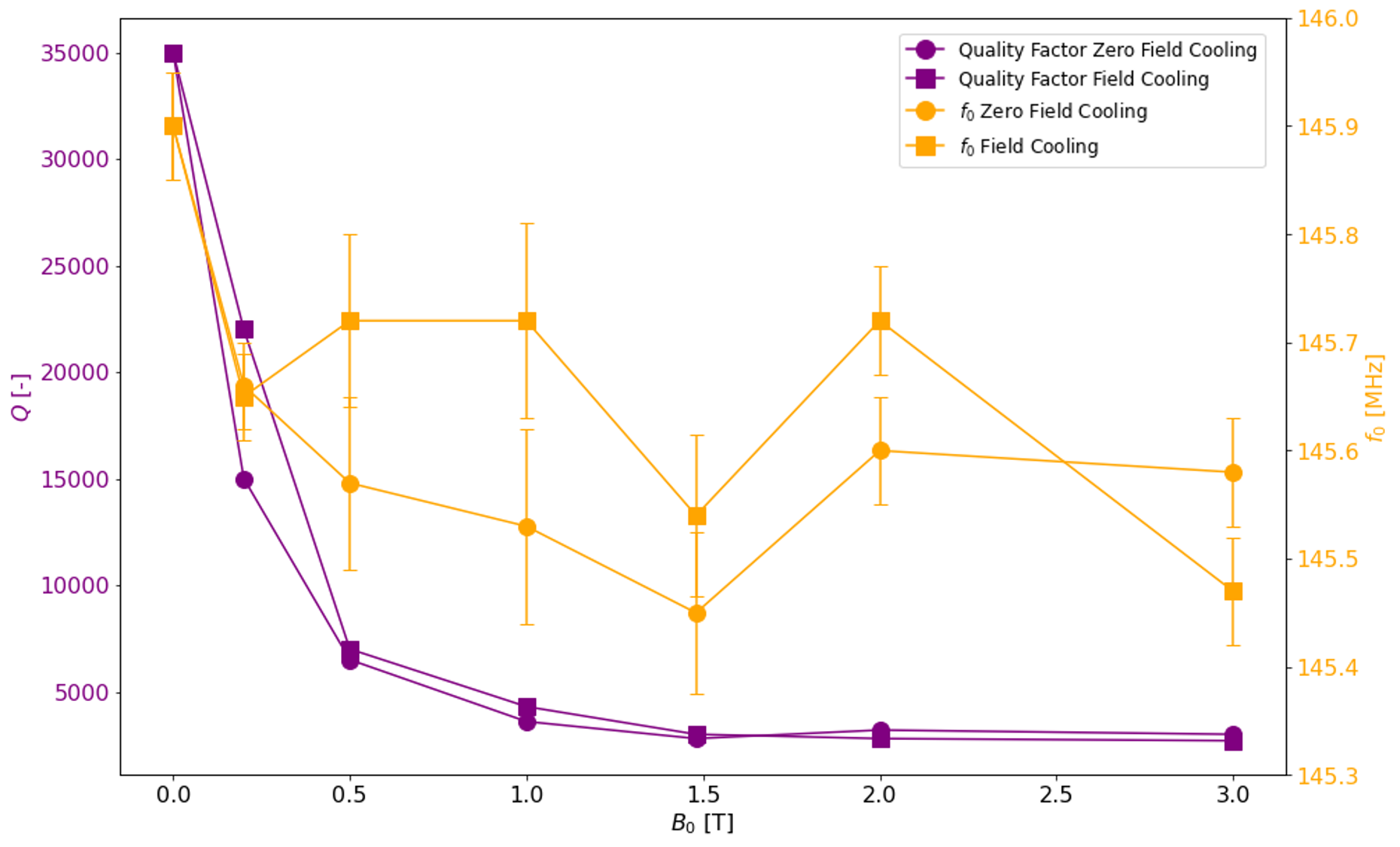
The simulated resonance frequency of the HTS MLTLR is 137.9 MHz and the one measured in Earth field, at 80 K, is 145.85 MHz. In such conditions Q ≈ 40,000. Q-factor and $$$f_0$$$, as a function of $$$B_0$$$ and the cooling history are presented fig.2. Q values drop rapidly with increasing $$$B_0$$$ until a saturation at higher fields. At ambient pressure and LN2 temperature, Q was reduced by 92% at 3T compared to zero-field, corresponding to a $$$f_0$$$ shift of -380 kHz.Q values did not seem to depend on how the RF coil is cooled whereas $$$f_0$$$ shifts seems to be stronger when the coil is cooled outside $$$B_0$$$ than when the coil is cooled inside the static field.The Q-factor decreased drastically, of about 95%, when the coil is loaded by the sample, as presented in the following table.| Experimental conditions | HTS MLTLR alone | HTS MLTLR with conductive sample ( σsample = 0.7 S/m; εr = 75 ) |
| Quality factor Q [-] | 38,000 | 1,700 |
| Resonance frequency $$$f_0$$$ | 145.90 | 145.90 |
Discussion & Conclusion
Based on the MLC principle, a new design of self-resonant superconducting reception surface coil for proton MRI at 3T has been simulated, manufactured and bench-characterized. The effects of the static $$$B_0$$$ field and cooling condition (field-cooling versus zero-field cooling) on both quality factor and resonance frequency of the HTS MLTLR coil have been investigated. $$$f_0$$$ shifts are comparable to the ones observed in the litterature [7]. The Q-factor decline in presence of $$$B_0$$$ was expected but is stronger than the ones reported in [7]. In presence of a conductive sample, the $$$f_0$$$ shift is negligible but the coupling with the sample induces a strong decrease of the Q-factor. Q still remains dozen times higher than copper MLCs [3], promising an interesting SNR gain.Acknowledgements
No acknowledgement found.References
[1] L. Darrasse and J.-C. Ginefri. Perspectives with cryogenic rf probes in biomedical mri. Biochimie, 85(9):915–937, 2003. Metabolic NMR.
[2] Zhoujian Li, Luc Darrasse, and Jean-Christophe Ginefri. Preliminary investigation on shielding-ring based technique for miniature monolithic rf coil decoupling. In Proceedings ISMRM, page 559, 2015.
[3] Roberta Frass-Kriegl, Sajad Hosseinnezhadian, Marie Poirier-Quinot, Elmar Laistler, and Jean-Christophe Ginefri. Multi-loop radio frequency coil elements for magnetic resonance imaging: Theory, simulation, and experimental investigation. Frontiers in Physics, 7, 2020.
[4] Patrick Gonord, S. K. Kan, Anne Leroy-Willig, and Claire Wary. Multigap parallel-plate bracelet resonator frequency determination and applications.Review of Scientific Instruments, 65:3363–3366, 1994.
[5] Camille Dubuc, Clément Thibault, Faouzi Boussaha, Jean-Christophe Ginefri, and Marie Poirier-Quinot. Proof of concept for auto-resonant structure to increase the field of view of surface coils. Proc. Intl. Soc. Mag. Reson.Med. 31, 2023.
[6] Aimé Labbé, Rose-Marie Dubuisson, Jean-Christophe Ginefri, Cornelis J.van der Beek, Luc Darrasse, and Marie Poirier-Quinot. Static field homogeneity artifacts due to magnetic flux expulsion by HTS coils for high-resolution magnetic resonance imaging. Applied Physics Letters,117(25):254101, 12 2020.
[7] Simon Lambert, Jean-Christophe Ginefri, Marie Poirier-Quinot, and Luc Darrasse. High-temperature superconducting radiofrequency probe for magnetic resonance imaging applications operated below ambient pressure in a simple liquid-nitrogen cryostat. Review of Scientific Instruments,84(5):054701, 05 2013.
Figures
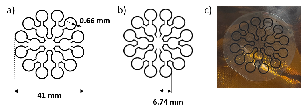
Figure 1 : Studied HTS Multi Loop Transmission Line Resonator (MLTLR) coil.
a) Design of the top superconducting track (300 nm YBaCuO) of the HTS coil.
b) Design of the bottom superconducting track (300 nm YBaCuO) of the HTS coil. 2 gaps of opposite phases are present on each track. The substrate is a 330 µm r-cut sapphire.
c) Picture of the coil (manufactured by Ceraco Ceramic Coating GmbH).