1567
A maze-like metasurface design as an efficient resonator for 7T MRI1Department of Brain Sciences, Weizmann Institute of Science, Rehovot, Israel, 2Life Sciences Core Facilities, Weizmann Institute of Science, Rehovot, Israel
Synopsis
Keywords: Non-Array RF Coils, Antennas & Waveguides, Non-Array RF Coils, Antennas & Waveguides
Motivation: Metamaterial-based designs have the potential to locally increase the RF field and to serve as resonators in MRI. However, many of the structure either include a high dielectric layer substrate or require large amount of lumped elements.
Goal(s): Our goal was to design a metamaterial without the need for either.
Approach: A novel metasurface was constructed from concentric split-rings alternatingly rotated by 90° - generating a maze-like configuration - which allowed to lower the resonant frequency.
Results: The novel maze-like metasurface achieved an RF field increase in the range of x1.5-2 compared to using a surface-coil of the same dimensions.
Impact: We demonstrated a new metasurface geometry that provides an efficient resonator at 298 MHz for 7T MRI. This design does not require high dielectric or lumped elements, which offers a simple implementation, a flexible setup and a high efficiency resonator.
Introduction
There is a growing interest in metamaterial-based designs for MRI to achieve local signal increase and improve efficiency of the RF coils1-8. Previous studies have demonstrated the potential of metamaterial-based designs to locally increase the RF field5-7 and to serve as alternative resonators1-4. However, many of the structure either include a high dielectric layer substrate or require large amount of lumped elements, both of which may reduce the efficiency and increase the complexity of the design. In this study, a new design was developed without the need for either (high dielectric and lumped elements); and merely uses copper strips. Instead of using a split-ring as the small sub-unit, here the structure was constructed from a set of concentric split-rings (each having two gaps) with alternating split-rings rotated by 90° - generating a maze-like configuration. This geometry was useful for both lowering the resonant frequency and increasing the efficiency of the RF field. The design was characterized in electromagnetic simulations and tested on a phantom in a 7T MRI. It was compared to a surface-loop of the same dimensions.Methods
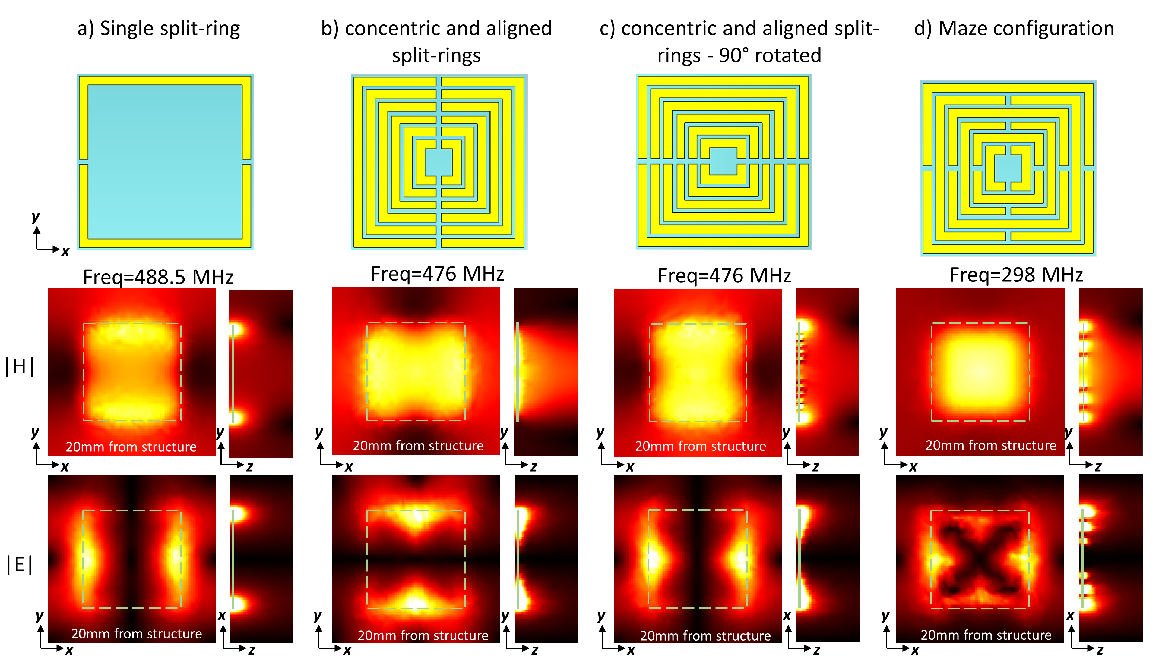
The new 6 split-ring metasurface structure (see Fig.1d) was designed to provide its lowest TE-mode — having the deepest penetration depth — at 298MHz. The final dimensions of the structure was set to 14x14x0.08 cm3. To achieve 298 MHz in simulations the copper strips were simulated attached to a thin 0.4 mm thick dielectric layer of just 2.6 relative permittivity. However, no dielectric was necessary in the actual setup (probably because the actual copper strips properties were different).EM simulations of the B1+ field were performed using CST Microwave Studio, Darmstadt, Germany. The simulations included both an eigen-mode solver to characterize the resonant mode (shown in Fig.1) and full EM simulations. The setup in both simulations and MRI measurements included a metasurface structure placed on top of a rectangular-shaped phantom consisting of sucrose, agarose and water (in simulation having relative permittivity of 53 and conductivity of 0.3 S/m). Virtual human model simulation used the Duke model and the metasurface structure was curved to best fit the head.
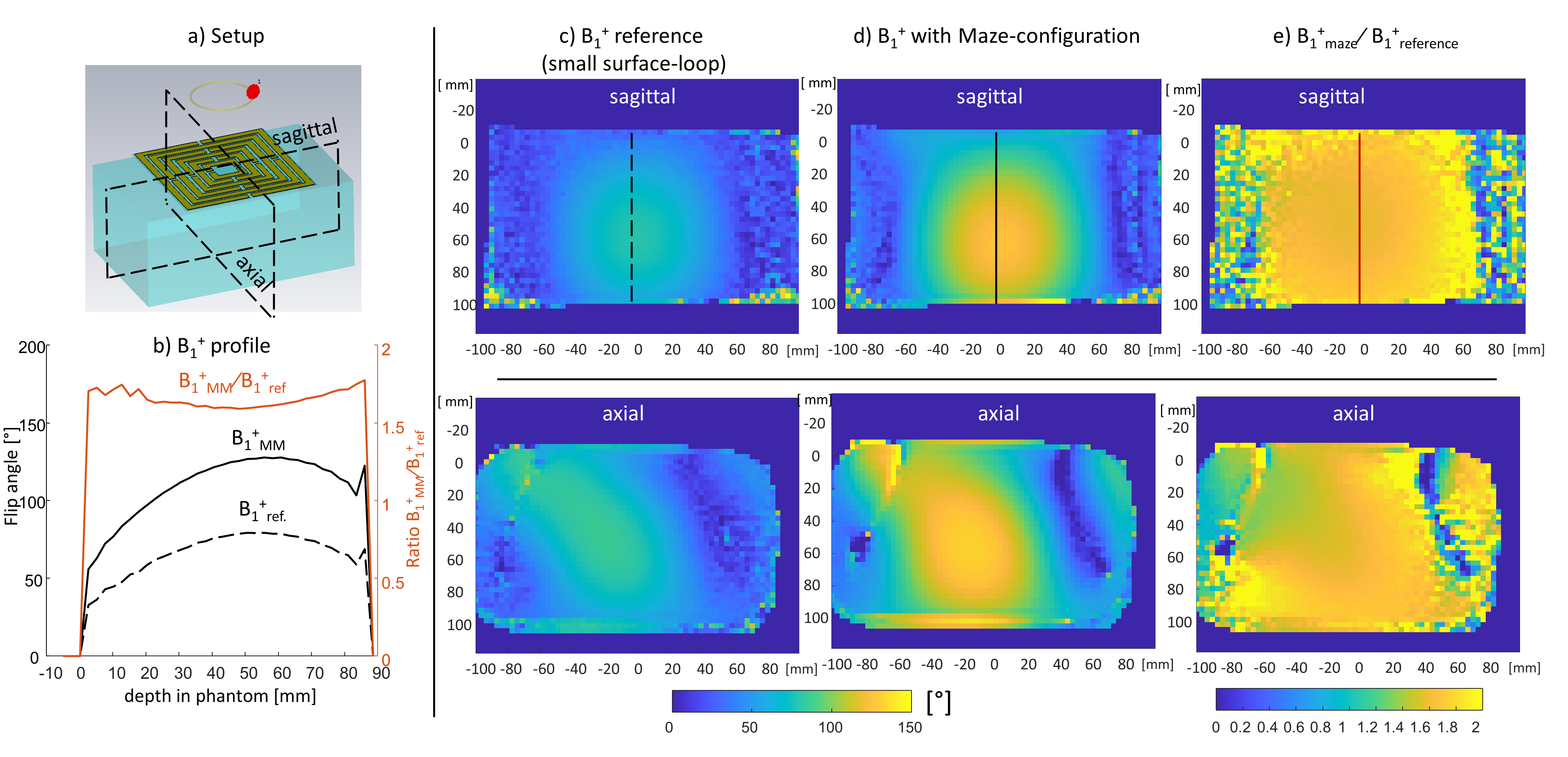
B1 maps were acquired with the vendor’s small surface-loop on a 7T Terra scanner (Siemens) which was placed above the metasurface structure (similar to shown in Fig. 2). B1+ map from the vendor’s sequence were collected using a 20x20 cm2 FOV and 2.5 x 2.5 x 3.5 mm3 resolution.
Results
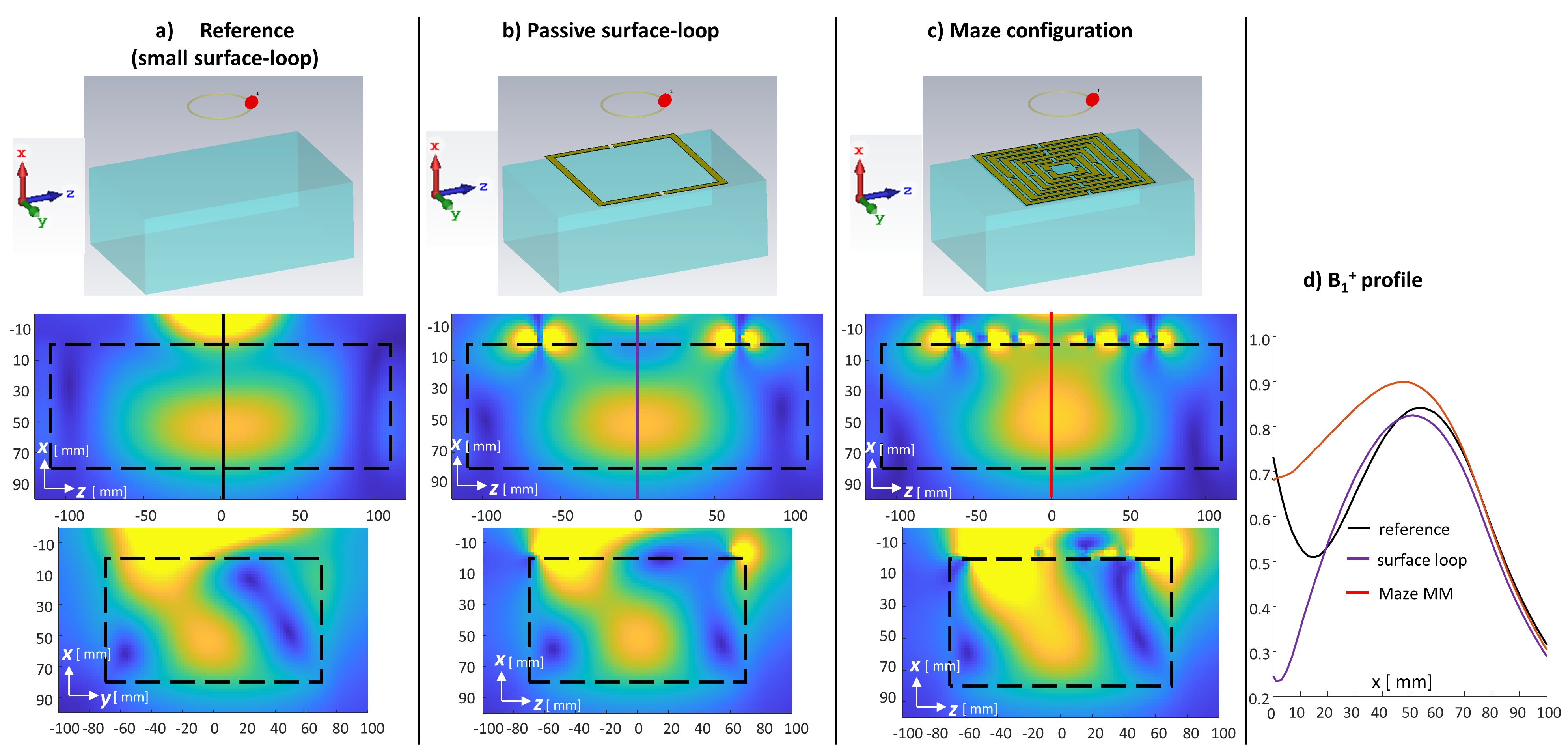
Fig. 1 compares eigen-mode |H| and |E| fields for different steps towards the maze-like structure. Fig.1a shows the RF fields due to a single outer split-ring, behaving similarly to those of a surface-loop with peak intensities close to the copper strips. Fig.1b) and c) show the fields with concentric split-rings which are not alternatingly rotated, improving the XY plane field homogeneity. Fig.1d shows the final maze-like configuration, achieving symmetric and “dense” field distributions. Note that alternatingly rotating the split-rings is fundamental to reducing the RF frequency to 298MHz.Fig.2 compared simulated B1+ distributions in setups with either a passive maze-like metasurface or a same-size passive surface-loop. Both setups were driven by a small surface-loop and included the rectangular phantom described in Methods. The maximal increase in RF field with the metasurface was x1.5 compared to the reference (no passive component), with a similar increase compared to the passive surface-loop.
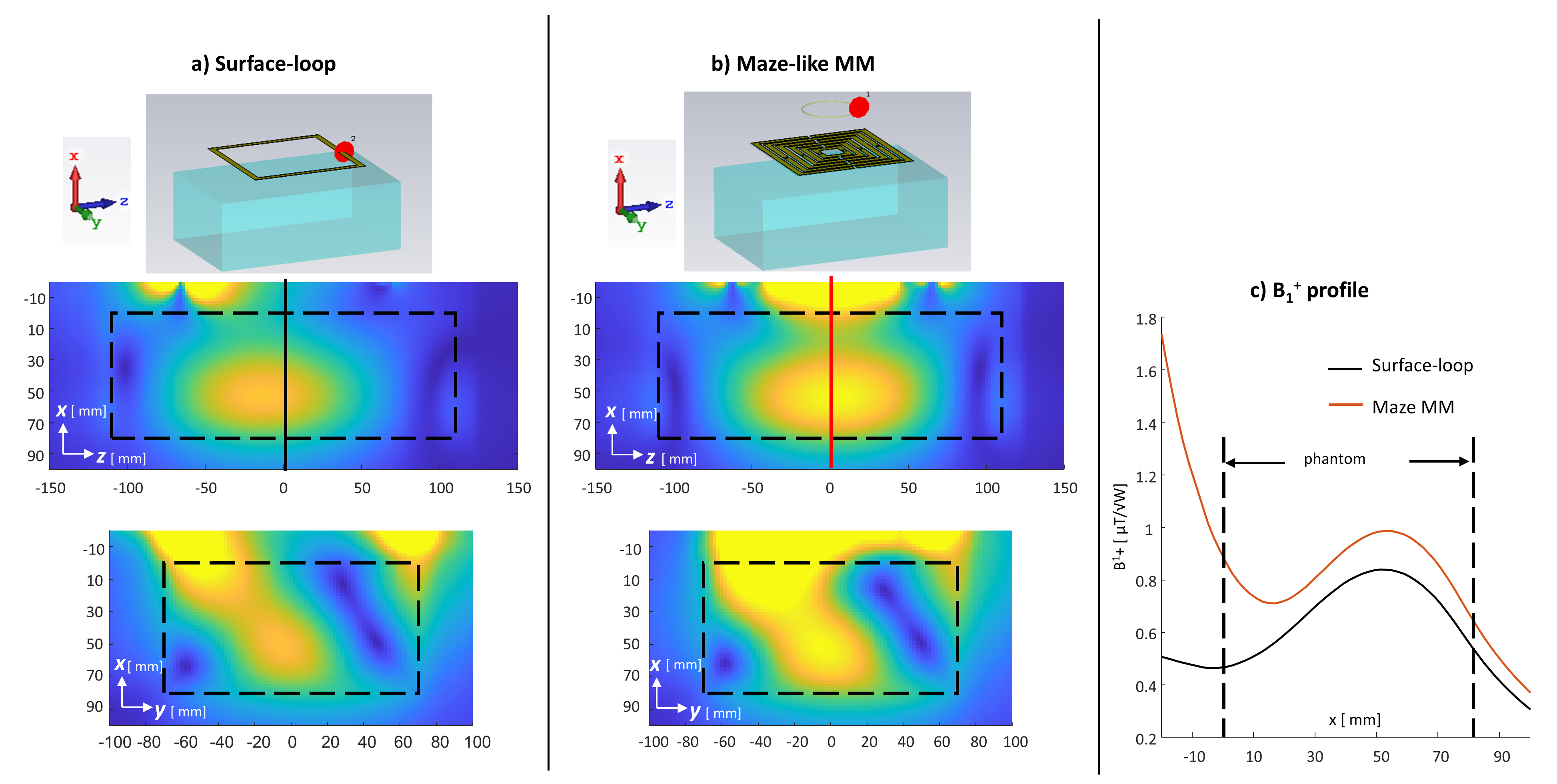
Fig.3 compared the simulated B1+ distribution between a setup driven by a surface-coil and one with the maze-like metasurface (same dimensions). The maximal increase in RF field with the metasurface was x1.9 compared to the surface coil with the same size.
Fig.4 shows measured B1+ maps of actual setups implementing those of Fig.2a and Fig.2c. An increase of ~x1.7 at the phantom’s center enables to reduce the reference amplitude.
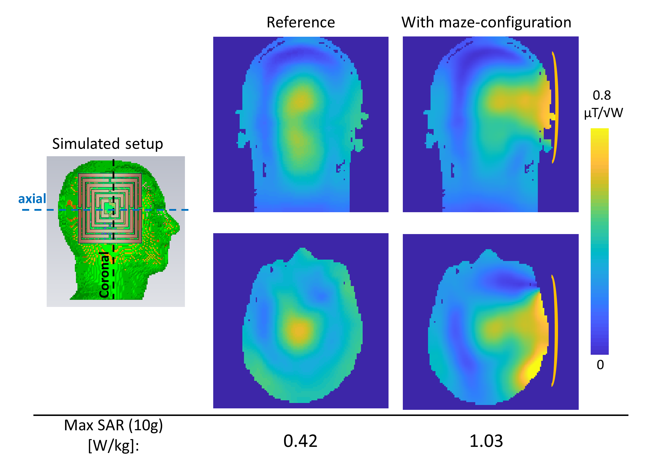
Finally, Fig. 5 shows a simulation of a human model for brain imaging, where the metasurface is added to increase the RF field locally. It showed a x1.9 increase in B1+ resulting in a transmit efficiency (B1+/√(Max SAR)) increase of x1.2, when accounting for the SAR increase.
Conclusions
This study presents a novel maze-like metasurface design, demonstrating an RF field increase in the range of x1.5-2 compared to using a surface-coil of the same dimensions. The advantage of this design is that it does not require a high dielectric substrate and can be implemented without lumped elements. The metasurface can be used as a driving element as well as a passively added structure, increasing significantly the RF field efficiency.Acknowledgements
No acknowledgement found.References
1. Algarín, J. M., Freire, M. J., Breuer, F., & Behr, V. C. (2014). Metamaterial magnetoinductive lens performance as a function of field strength. Journal of Magnetic Resonance, 247, 9-14.
2. Gomez, T. S. V., Dubois, M., Rustomji, K., Georget, E., Antonakakis, T., Vignaud, A., ... & Abdeddaim, R. (2022). Hilbert fractal inspired dipoles for passive RF shimming in ultra-high field MRI. Photonics and Nanostructures-Fundamentals and Applications, 48, 100988.
3. Motovilova, E., Sandeep, S., Hashimoto, M., & Huang, S. Y. (2019). Water-tunable highly sub-wavelength spiral resonator for magnetic field enhancement of MRI coils at 1.5 T. IEEE Access, 7, 90304-90315.
4. Lippke, M., Stoja, E., Philipp, D., Konstandin, S., Jenne, J., Bertuch, T., & Günther, M. (2022, September). Investigation of a Digitally-Reconfigurable Metasurface for Magnetic Resonance Imaging. In 2022 52nd European Microwave Conference (EuMC) (pp. 668-671). IEEE.
5. Slobozhanyuk, A. P., Poddubny, A. N., Raaijmakers, A. J., van den Berg, C. A., Kozachenko, A. V., Dubrovina, I. A., ... & Belov, P. A. (2016). Metasurfaces: Enhancement of Magnetic Resonance Imaging with Metasurfaces (Adv. Mater. 9/2016). Advanced Materials, 28(9), 1831-1831.
6. Schmidt, R., Slobozhanyuk, A., Belov, P., & Webb, A. (2017). Flexible and compact hybrid metasurfaces for enhanced ultra high field in vivo magnetic resonance imaging. Scientific reports, 7(1), 1-7.
7. Schmidt, R., & Webb, A. (2017). Metamaterial combining electric-and magnetic-dipole-based configurations for unique dual-band signal enhancement in ultrahigh-field magnetic resonance imaging. ACS applied materials & interfaces, 9(40), 34618-34624.
8. Webb, A., Shchelokova, A., Slobozhanyuk, A., Zivkovic, I., & Schmidt, R. (2022). Novel materials in magnetic resonance imaging: high permittivity ceramics, metamaterials, metasurfaces and artificial dielectrics. Magnetic Resonance Materials in Physics, Biology and Medicine, 35(6), 875-894.
Figures