1566
Toward a 16-channel loop-dipole combined dielectric resonator antenna array for human brain MRI at 7T using pTX1CIBM Center for Biomedical Imaging, Lausanne, Switzerland, 2Animal Imaging and Technology, EPFL, Lausanne, Switzerland
Synopsis
Keywords: Non-Array RF Coils, Antennas & Waveguides, RF Arrays & Systems
Motivation: To develop a new generation of head coils for ultrahigh field MRI using loop-dipole combined dielectric resonator antenna arrays.
Goal(s): To construct and evaluate an 8-channel loop-coupled dielectric resonator antenna array for brain MRI at 7T.
Approach: Electromagnetic field simulations in a spherical phantom and Duke for different types of RF feeds were performed. An 8-channel, loop-coupled dielectric resonator antenna array was constructed using 8 ceramic, rectangular dielectric blocks (εr=275, σ=0.068 S/m).
Results: An 8-channel loop-coupled dielectric resonator antenna array was successfully constructed and evaluated at the bench as well as in preliminary phantom experiments at 7T using pTX system.
Impact: This study is an important step to improve transmit and receive performance of head coils for neuroimaging at 7T.
Introduction
Brain MRI at 7T is largely addressed by RF coils which are commercially available. There is, however, growing evidence, that traditional approaches using only loop coil elements are not sufficient to approach the ultimate intrinsic SNR, especially at 7T and higher1. This provides a great motivation to explore novel approaches which would ultimately advance neuroimaging at 7T. To address it, innovative strategies such as hybrid loop-dipole2 and dipolectric antenna3 arrays were proposed and their advantages were demonstrated. In the latter one, dielectric resonator antennas (DRAs) were used. DRAs can produce more efficient transmit field efficiency in the periphery vs. their loop-like counterparts. Furthermore, no additional decoupling circuits are required when DRAs are used in multi-channel array configurations. The number of studies focusing on DRAs for 7T MRI is still limited4,5. Recently it was shown that the type of RF feed used for DRAs is critical to optimize transmit (TX) and receive (RX) performance6. Instead of using a standard, single RF feed, a multi-feed, loop-dipole combined approach was proposed. That strategy can be used to triple the number of channels in a given DRA array without any significant increase in mutual coupling. In the previous work6, however, no experimental validation was provided. Therefore, our goal was to construct an 8-channel loop-coupled DRA array using custom-tailored ceramic blocks for brain MRI at 7T which is an intermediate step toward the development of the first 16-channel loop-dipole combined DRA array.Methods
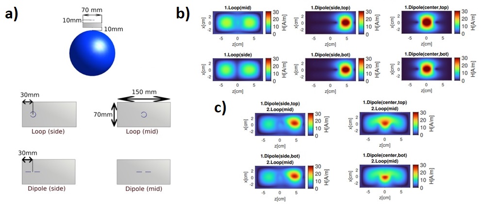
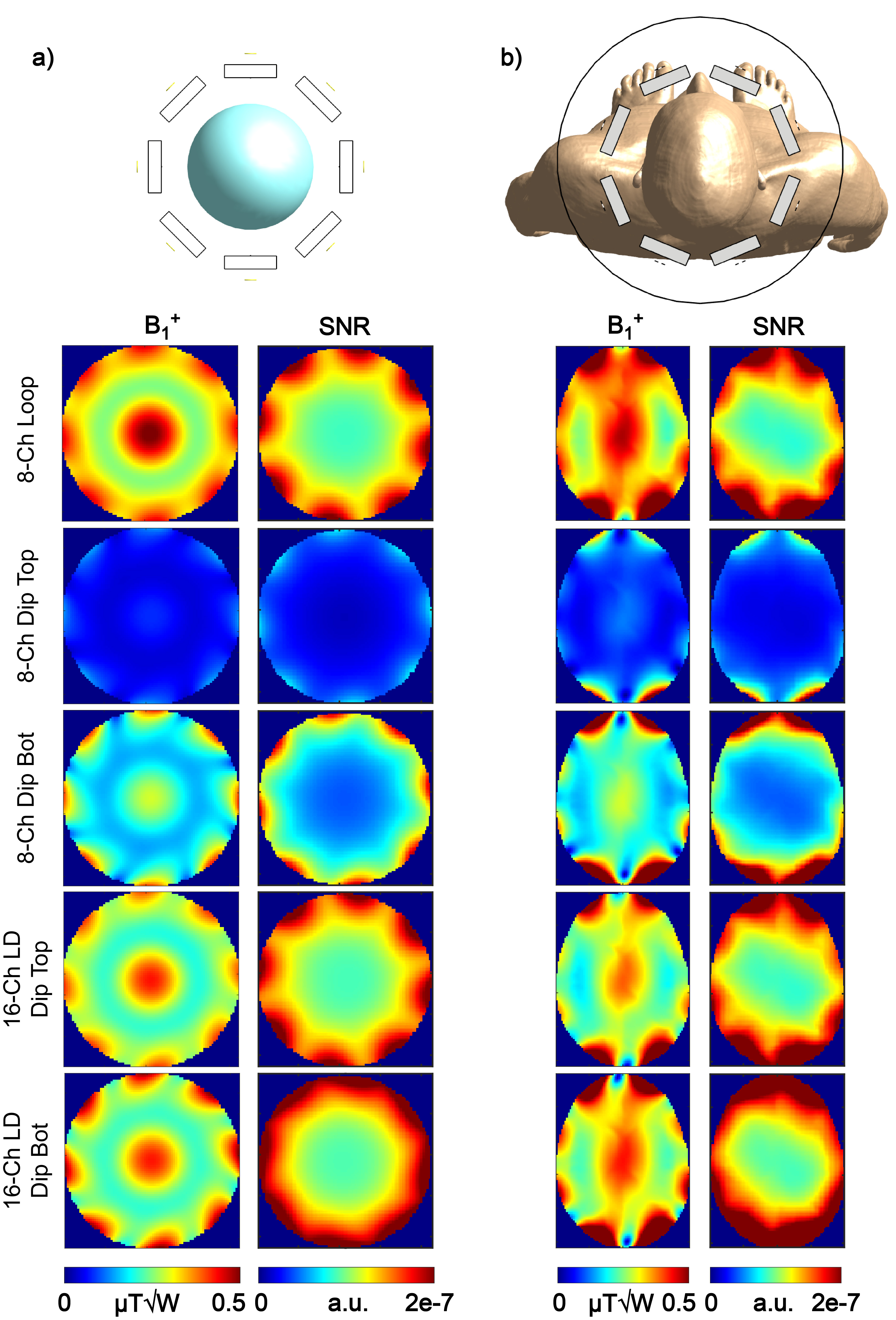
Electromagnetic field simulations in a spherical phantom (radius=85mm, εr=77, σ=1.09S/m) and human voxel model Duke were conducted using Sim4Life (Zurich Medtech,Switzerland). The DRA array was designed using 8 rectangular dielectric blocks ((150x70x17.5)mm3; εr =275, σ=0.068 S/m). The DRAs were positioned concentrically (inner diameter=240 mm), and they were driven in different TX modes using the following RF feed types: loop-only, dipole-only (top), dipole-only (bottom), loop-dipole (dipole top) and loop-dipole (dipole bottom) – Fig.1. In TX, each array was driven in circularly polarized (CP) mode with a phase increment 45º/element. Transmit field efficiency was defined as B1+/√P, where P is the input power. Signal-to-noise ratio (SNR) was evaluated using an implementation of the Roemer’s algorithm7 which was based on the scattering parameter matrix (S-matrix) formalism proposed earlier8. The 8-channel loop-coupled DRA array for brain MRI at 7T was constructed using rectangular, ceramic blocks (HyQRS Solution, PA, USA) with the same properties as the ones used in simulations. Each DRA was fed using a small (diameter = 15 mm), loop element which was: tuned to the resonance frequency (297.2 MHz), matched to 50 Ohm and positioned 15 mm above the block. S-matrices were measured using a 4-channel vector network analyzer (Agilent Technologies, USA) when the array was placed inside a gradient shield dummy (diameter = 400 mm). MR phantom experiments were performed using a head-only 7T MRI scanner equipped with a pTX 2.3 system (Siemens Healthineers, Germany). RF shimming was performed using the approach described earlier9.Results
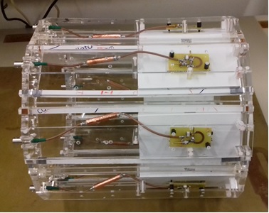
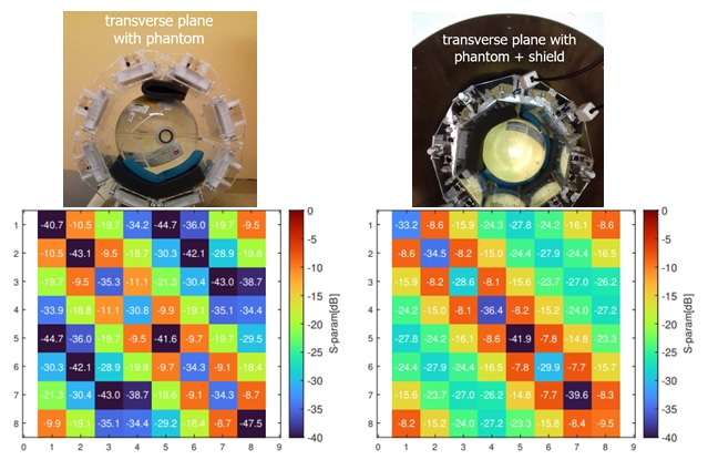
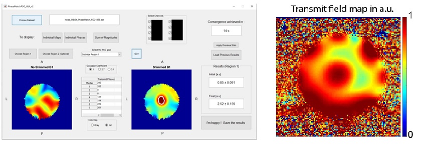
A loop element placed on the top of a DRA induced a higher-order transverse electric mode in all three investigated positions (Fig. 1). Simulations showed that B1+ efficiency (spherical phantom, Duke) was the highest for the loop-only, while the highest SNR was the highest for the loop-dipole (Fig.2); 16-channel loop-dipole combined DRA array provided up to 1.5-fold (phantom) and 2-fold (Duke) SNR increase in the periphery vs. 8-channel loop-coupled DRA array. The 8-channel loop-coupled DRA array was constructed (Fig. 3), and bench measurements revealed that coupling between neighboring elements of the 8-channel DRA array was between -8.7 and -11.1 dB and between -7.7 and -8.6 dB when the array was placed outside and inside the gradient shield dummy, respectively (Fig. 4). The 8-channel loop-coupled DRA array was used in preliminary phantom experiments showing that RF shimming can significantly improve TX performance of the array (Fig. 5).Discussion and Conclusion
In this work a novel 8-channel loop-coupled DRA array for brain MRI was designed, constructed, evaluated at the bench and used in preliminary phantom experiments at 7T pTX system. Each DRA was tuned to 297.2 MHz and matched to 50Ω; a moderate coupling was observed between the neighboring elements, and no additional decoupling circuits were used. It was demonstrated that RF shimming for the proposed array using a 7T pTX system is feasible. This study is a major step toward the development of a 16-channel loop-dipole DRA array which is expected to bring significant RX performance gains. The ongoing work is focused on comparing the constructed 8-channel loop-coupled DRA array with other head arrays which are available in our laboratory: 1TX/32R, 8TXRX and 8TX/32RX.Acknowledgements
We acknowledge access to the facilities and expertise of the CIBM Center for Biomedical Imaging, a Swiss research center of excellence founded and supported by Lausanne University Hospital (CHUV), University of Lausanne (UNIL), Ecole polytechnique fédérale de Lausanne (EPFL), University of Geneva (UNIGE) and Geneva University Hospitals (HUG). We also acknowledge previous work of Jeremie Clement (Siemens Healthineers) on the development of GUI used for RF shimming.References
1. Lattanzi et al.,
MRM 2018.
2. Avdievich et
al., MRM 2022.
3.
Wenz et al., MRM 2023.
4. Aussenhofer and
Webb, MRM 2012.
5. Aussenhofer and
Webb, JMR 2014.
6.
Wenz and Dardano, MAGMA 2023.
7.
Roemer et al., MRM 1990.
8. Kuehne et al.
MRM 2015.
9. Clement et al.
MRM 2019.
Figures