1563
Wireless Split Ring Resonator Metasurface Enhances Transmission Efficiency of Surface Loop Arrays at 7T1Berlin Ultra High Field Facility, Berlin Ultrahigh Field Facility (B.U.F.F.), Max-Delbrück Center for Molecular Medicine in the Helmholtz Association, Berlin, Germany, 2Experimental and Clinical Research Center (ECRC), a joint cooperation between the Charité Medical Faculty and the Max-Delbrück Center for Molecular Medicine in the Helmholtz Association, Berlin, Germany, 3Department of Brain Sciences, Department of Brain Sciences, Weizmann Institute of Science, Rehovot, Israel, 4Chair of Medical Engineering, Chair of Medical Engineering, Technische Universität Berlin, Berlin, Germany, 5MRI.TOOLS GmbH, Berlin, Germany
Synopsis
Keywords: Non-Array RF Coils, Antennas & Waveguides, High-Field MRI, Split Ring Resonator; Metamaterial surface; Loop Array
Motivation: Metasurfaces are conceptually appealing for enhancing RF coil performance due to added degrees of freedom for shaping electromagnetic fields.
Goal(s): This work focuses on development and validation of a novel split ring resonator (SRR) based metasurface for improving the performance of a two-channel surface loop array at 7.0 T.
Approach: Application of a magnetic field perpendicular to SRR induces electromotive force, forming an LC circuit with resonance frequency as currents circulate between the rings. This property benefits MRI transmission field enhancement.
Results: Our simulations and experimental results demonstrate that wireless metasurfaces enhance transmission efficiency of a two-channel surface loop coil array at 7T.
Impact: Our approach provides technical foundation for development, implementation and validation of novel metasurfaces for RF arrays customized for UHF-MRI. Our metasurface offers customizable resonance properties by adjusting unit cells, periodicity, or structure placement to enhance transmit field efficiency and uniformity.
PURPOSE
Ultra-high field (UHF, B0≥7T) MRI, offers superior signal-to-noise (SNR) ratios and local transceive (TxRx) RF coils enable enhanced tissue excitation1,2. TxRx surface loop coils provide higher SNR near the patient's surface, but at UHF due to wavelength shortening, they produce non-uniform transmit B1+ field distribution1-4. Metasurfaces (MS) involve planar versions of metamaterials. RF wave propagation manipulation using MS is conceptually appealing to enhance B1+ field uniformity, depth penetration and sensitivity of MRI5-10. Split ring resonators (SRRs) are commonly used in metamaterials. SRR possess a large magnetic polarizability and magnetic dipole moment therefore producing the desired magnetic response to applied electromagnetic fields and are beneficial for B1+ field enhancement in MRI11-13. Double SRRs are more effective as they reduce the electric dipole moment with two concentric rings, while preserving the magnetic dipole moment11. Recognizing this opportunity our work examines B1+ gain at 7T using an MS based on an array of SRR unit cells in conjunction with a two-channel TxRx loop array (2L). Our simulations and phantom experiments demonstrated a significant improvement in B1+ at 7T when using 2L array in combination with MS (2L+MS).METHODS
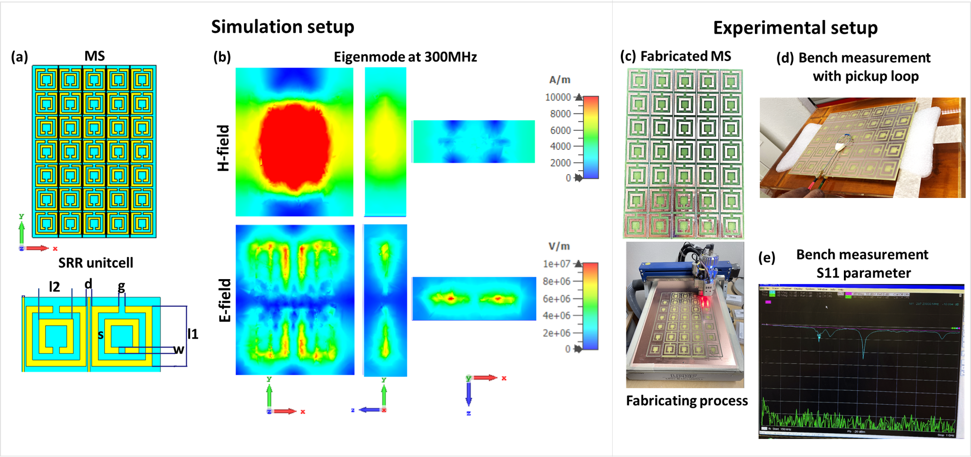
The MS and 2L were designed in CST microwave studio and constructed on a copper-clad FR4 PCB (εr=4.5) using a PCB prototyping machine (PROTMATE44, LPKF). Bench measurements were done with an 8-channel vector network analyzer (VNA) (Rohde & Schwarz).The MS (size:264x190x2mm) comprises a 5x7 array of SRR unit cells with 4 long strips [Fig. 1a]. The resonant eigenmode of MS was simulated in the eigenmode solver of CST. The frequency of the MS prototype was determined by measuring the return loss (S11) using a 40 mm-diameter pickup loop coil with VNA.
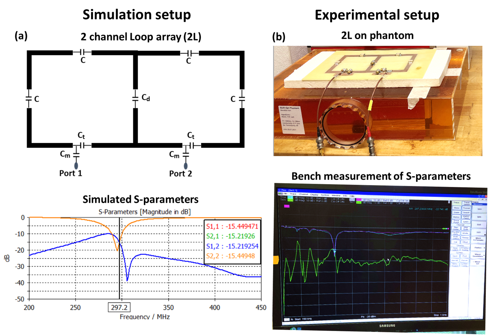
The two-channel rectangular surface TxRx loop array (200x100x1mm) incorporated four distributed fixed capacitors. The loop was tuned and matched using capacitive tuning (Ct) and matching (Cm) networks, and decoupled from each other with a shared decoupling capacitor (Cd) on a common conductor. The two feeding ports of the 2L were connected to the transmit path of the TxRX switch (Stark Contrast Erlangen, Germany) with a 1:2 power splitter without any phase shift. The loop was tuned and matched to 297.2MHz [Fig. 2].
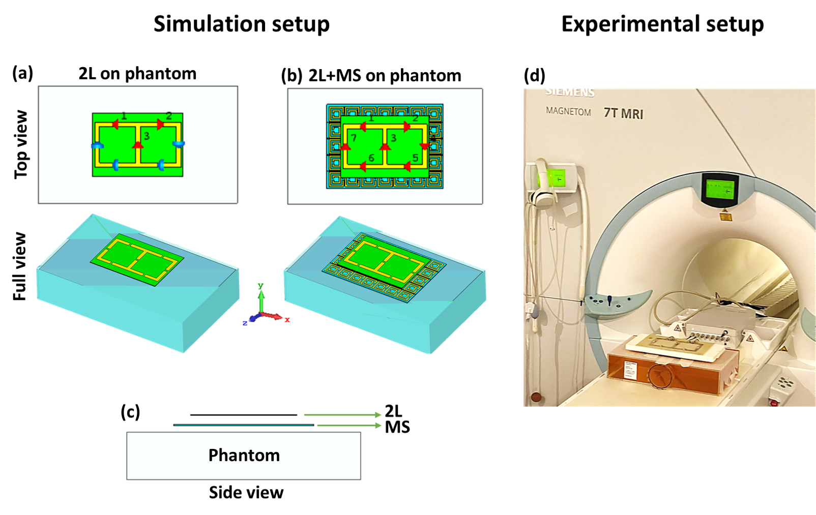
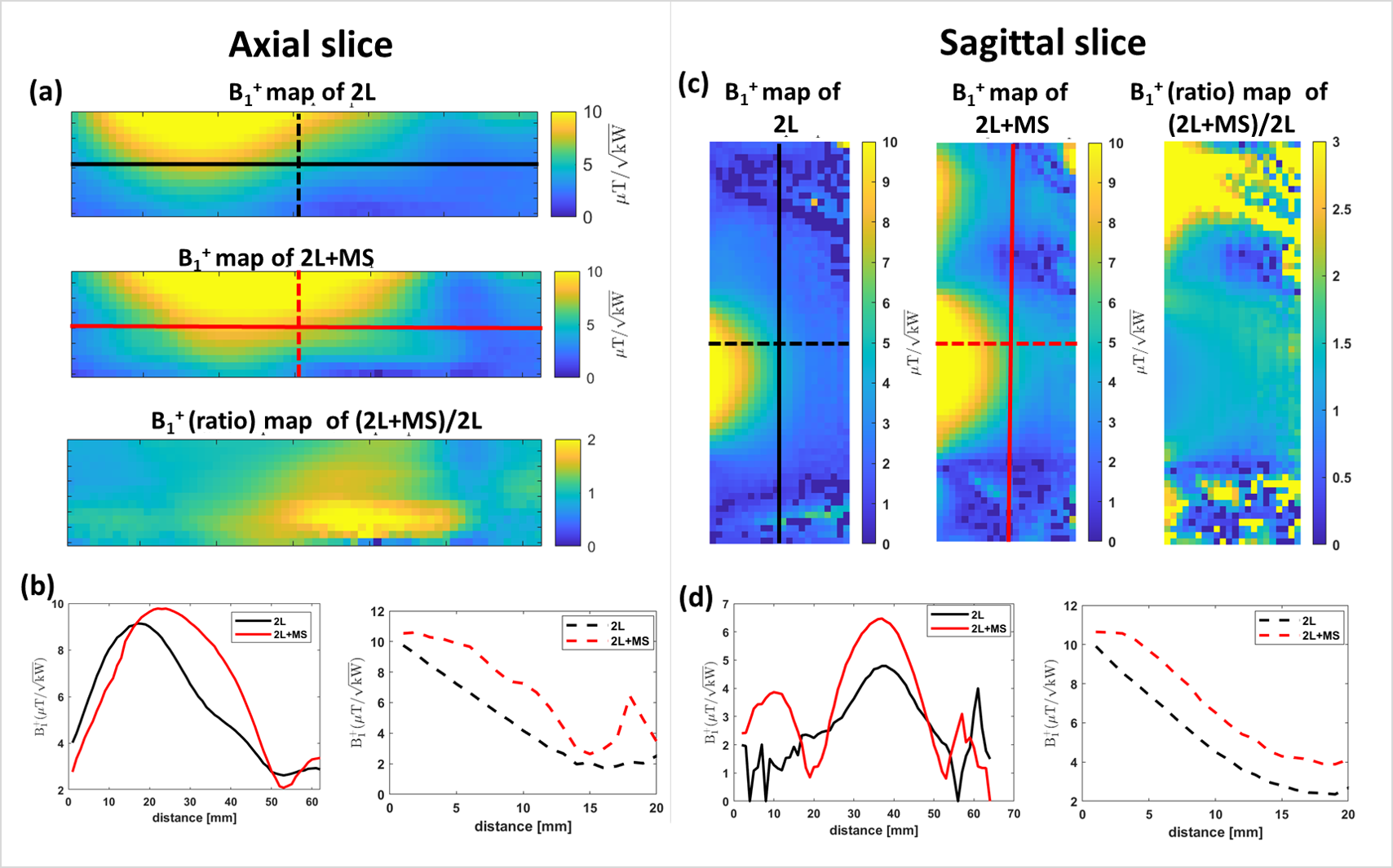
For performance evaluation of MS, phantom images were acquired for 2L with and without MS. These images were obtained using a rectangular phantom (45x27x10cm) (εr=58; σ=0.77S/m) filled with water, PVP, and salt. MRI experiments were performed using Siemens 7.0 T (MAGNETOM, Siemens Healthineers, Germany) [Fig. 3]. A gradient echo sequence (FLASH) was used for MRI with spatial resolution = 3.5x3.5x3.5 mm3; TE/TR=2/440ms; Flip angle= 840; FoV= 450x43.8 mm; transmitter voltage =160V. Transmit B1+ mapping was conducted in the phantom using 3D actual flip angle imaging (AFI14,15) with spatial resolution = 4x4x4 mm3, TR1/TR2=24/104ms; TE=2.9ms; nominal flip angle =900; FoV= 320x68.8 mm; transmitter voltage=200V. Evaluation of the relative transmit B1+ field distribution were assessed for central transversal slice through the rectangular phantom.
RESULTS
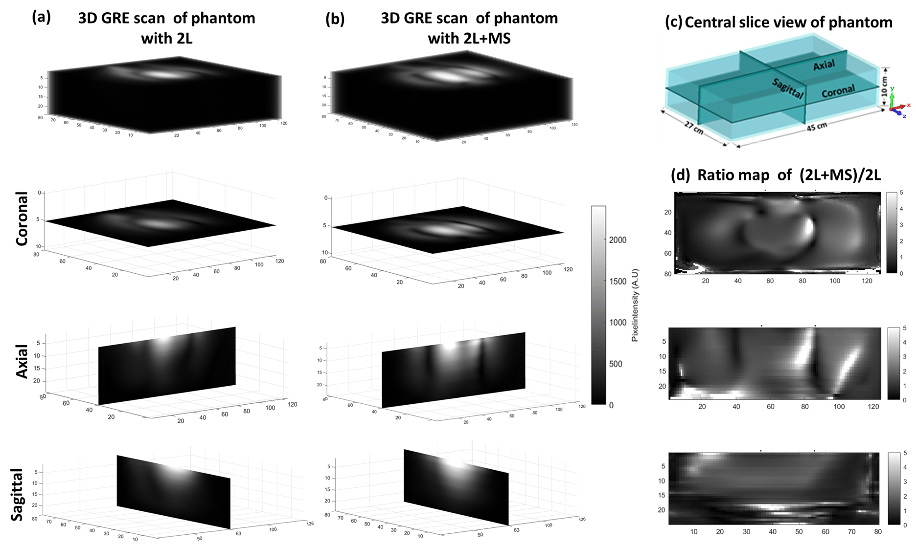
The eigenmode of MS shows the lowest TE mode that provides deep penetration depth of the magnetic (H) field at 300MHz [Fig. 1b]. Our VNA measurements revealed a resonant mode at 297.2MHz with the MS placed on the phantom [Fig. 1d,e]. These results are in good agreement with our simulations and with the experimental S11 parameter.Figure 4 shows phantom data obtained from 3D GRE MRI. The 2L+MS setup yielded 55%, 37%, 34% higher signal intensity for central axial, sagittal and coronal slices versus the 2L setup. Figure 5, summarizes the results obtained for B1+ mapping. The B1+ maps demonstrate 19% (axial) and 48% (sagittal) enhancement and improved FoV coverage for 2L+MS setup over the 2L setup. The 2L+MS setup facilitated 17% enhancement in B1+ uniformity for the central sagittal slice. To summarize, constructive redistribution of the magnetic field facilitated by the wireless MS benefits both B1+ and signal intensity enhancement.
DISCUSSION & CONCLUSION
Our results demonstrate that wireless split ring resonator metasurface enhances the transmission efficiency of a two-channel surface loop array at 7T. The benefit of our MS is that their eigenmode properties can be customized by adjusting unit cells, periodicity, or structure placement relative to the imaging location for enhanced transmit efficiency and field homogeneity. Also, an unbalanced loop coil approach can be combined with the MS’s resonance eigenmode tuning to further shape the E and H field. Our cost-effective, in-house production of thin MS on FR4 PCB eliminates the need for bulky and expensive dielectric substrates for the MS. Our preliminary results provide the technical foundation for a loop coil array tailored for lumber spine MRI at 7.0 T.Acknowledgements
This project is a joint collaboration between the Max Delbrück Center for Molecular Medicine (MDC) and the Weizmann Institute of Science, Israel as part of the Helmholtz International Research School (HIRS) for Imaging and Data Science from the NAno to the MESo (iNAMES).References
1. Hernandez D, Kim KN. A Review on the RF Coil Designs and Trends for Ultra High Field Magnetic Resonance Imaging. Investig Magn Reson Imaging. 2020 Sep;24(3):95-122. https://doi.org/10.13104/imri.2020.24.3.95
2. Lakshmanan K, Cloos M, Brown R, Lattanzi R, Sodickson DK, Wiggins GC. The "Loopole" Antenna: A Hybrid Coil Combining Loop and Electric Dipole Properties for Ultra-High-Field MRI. Concepts Magn Reson Part B Magn Reson Eng. 2020;2020:8886543. doi: 10.1155/2020/8886543. Epub 2020 Sep 7. PMID: 34140840; PMCID: PMC8207246.
3. Weinberger O, Winter L, Dieringer MA, Els A, Oezerdem C, Rieger J, Kuehne A, Cassara AM, Pfeiffer H, Wetterling F, Niendorf T. Local Multi-Channel RF Surface Coil versus Body RF Coil Transmission for Cardiac Magnetic Resonance at 3 Tesla: Which Configuration Is Winning the Game? PLoS One. 2016 Sep 6;11(9):e0161863. doi: 10.1371/journal.pone.0161863. PMID: 27598923; PMCID: PMC5012568.
4. Vaidya MV, Deniz CM, Collins CM, Sodickson DK, Lattanzi R. Manipulating transmit and receive sensitivities of radiofrequency surface coils using shielded and unshielded high-permittivity materials. MAGMA. 2018 Jun;31(3):355-366. doi: 10.1007/s10334-017-0657-5. Epub 2017 Nov 6. PMID: 29110240; PMCID: PMC5936683.
5. Webb A, Shchelokova A, Slobozhanyuk A, Zivkovic I, Schmidt R. Novel materials in magnetic resonance imaging: high permittivity ceramics, metamaterials, metasurfaces and artificial dielectrics. MAGMA. 2022 Dec;35(6):875-894. doi: 10.1007/s10334-022-01007-5. Epub 2022 Apr 26. PMID: 35471464; PMCID: PMC9596558.
6. Schmidt R, Slobozhanyuk A, Belov P, Webb A. Flexible and compact hybrid metasurfaces for enhanced ultra high field in vivo magnetic resonance imaging. Sci Rep. 2017 May 10;7(1):1678. doi: 10.1038/s41598-017-01932-9. PMID: 28490772; PMCID: PMC5431866.
7. Alipour, A, Seifert, AC, Delman, BN, Hof, PR, Fayad, ZA, Balchandani, P. Enhancing the brain MRI at ultra-high field systems using a meta-array structure. Med Phys. 2023; 1-13. https://doi.org/10.1002/mp.16801
8. Vorobyev V, Shchelokova A, Efimtcev A, Baena JD, Abdeddaim R, Belov P, Melchakova I, Glybovski S. Improving B1+ homogeneity in abdominal imaging at 3 T with light, flexible, and compact metasurface. Magn Reson Med. 2022 Jan;87(1):496-508. doi: 10.1002/mrm.28946. Epub 2021 Jul 27. PMID: 34314033.
9. Sokol SL, Colwell ZA, Kandala SK, Imani MF, Sohn SM. Flexible Metamaterial Wrap for Improved Head Imaging at 3 T MRI With Low-Cost and Easy Fabrication Method. IEEE Antennas Wirel Propag Lett. 2022 Oct;21(10):2075-2079. doi: 10.1109/lawp.2022.3190696. Epub 2022 Jul 13. PMID: 36388763; PMCID: PMC9648536.
10. Luo S, Hao J, Ye F, Li J, Ruan Y, Cui H, Liu W, Chen L. Evolution of the Electromagnetic Manipulation: From Tunable to Programmable and Intelligent Metasurfaces. Micromachines (Basel). 2021 Aug 20;12(8):988. doi: 10.3390/mi12080988. PMID: 34442610; PMCID: PMC8399928.
11. Moghbeli, E., Askari, H.R. & Forouzeshfard, M.R. Analyzing the effect of geometric parameters of double split ring resonator on the effective permeability and designing a cloak of invisibility in microwave regime. Appl. Phys. A 124, 361 (2018). https://doi.org/10.1007/s00339-018-1774-3
12. C. Saha, J. Y. Siddiqui, D. Guha and Y. M. M. Antar, "Square Split Ring Resonators: Modelling of resonant frequency and polarizability," 2007 IEEE Applied Electromagnetics Conference (AEMC), Kolkata, India, 2007, pp. 1-3, doi: 10.1109/AEMC.2007.4638039.
13. J. B. Pendry, A. J. Holden, D. J. Robbins and W. J. Stewart, "Magnetism from conductors and enhanced nonlinear phenomena," in IEEE Transactions on Microwave Theory and Techniques, vol. 47, no. 11, pp. 2075-2084, Nov. 1999, doi: 10.1109/22.798002.
14. Yarnykh VL. Actual flip-angle imaging in the pulsed steady state: a method for rapid three-dimensional mapping of the transmitted radiofrequency field. Magn Reson Med. 2007 Jan;57(1):192-200. doi: 10.1002/mrm.21120. PMID: 17191242.
15. Eigentler TW, Winter L, Han H, Oberacker E, Kuehne A, Waiczies H, Schmitter S, Boehmert L, Prinz C, TrefnaHD, Niendorf T. Wideband Self-Grounded Bow-Tie Antenna for Thermal MR. NMR Biomed. 2020May;33(5):e4274.
Figures