1562
SNR comparison between Loop and Sleeve antennas for human head arrays at 10.5T1Hankuk University of Foreign Studies, Yongin, Korea, Republic of, 2Center for Magnetic Resonance Research, Minneapolis, MN, United States, 3Medical Device Development Center, Daegu-Gyeongbuk Medical Innovation Foundation, Daegu, Korea, Republic of
Synopsis
Keywords: RF Arrays & Systems, RF Arrays & Systems
Motivation: To explore the SNR performance of Loop and Sleeve antennas for multi-channel human head imaging at 10.5T.
Goal(s): Validation of achievable receive performance of loop and sleeve antennas with same number of channels.
Approach: Simulation based analysis of SNR between loop and sleeve antennas with same channels.
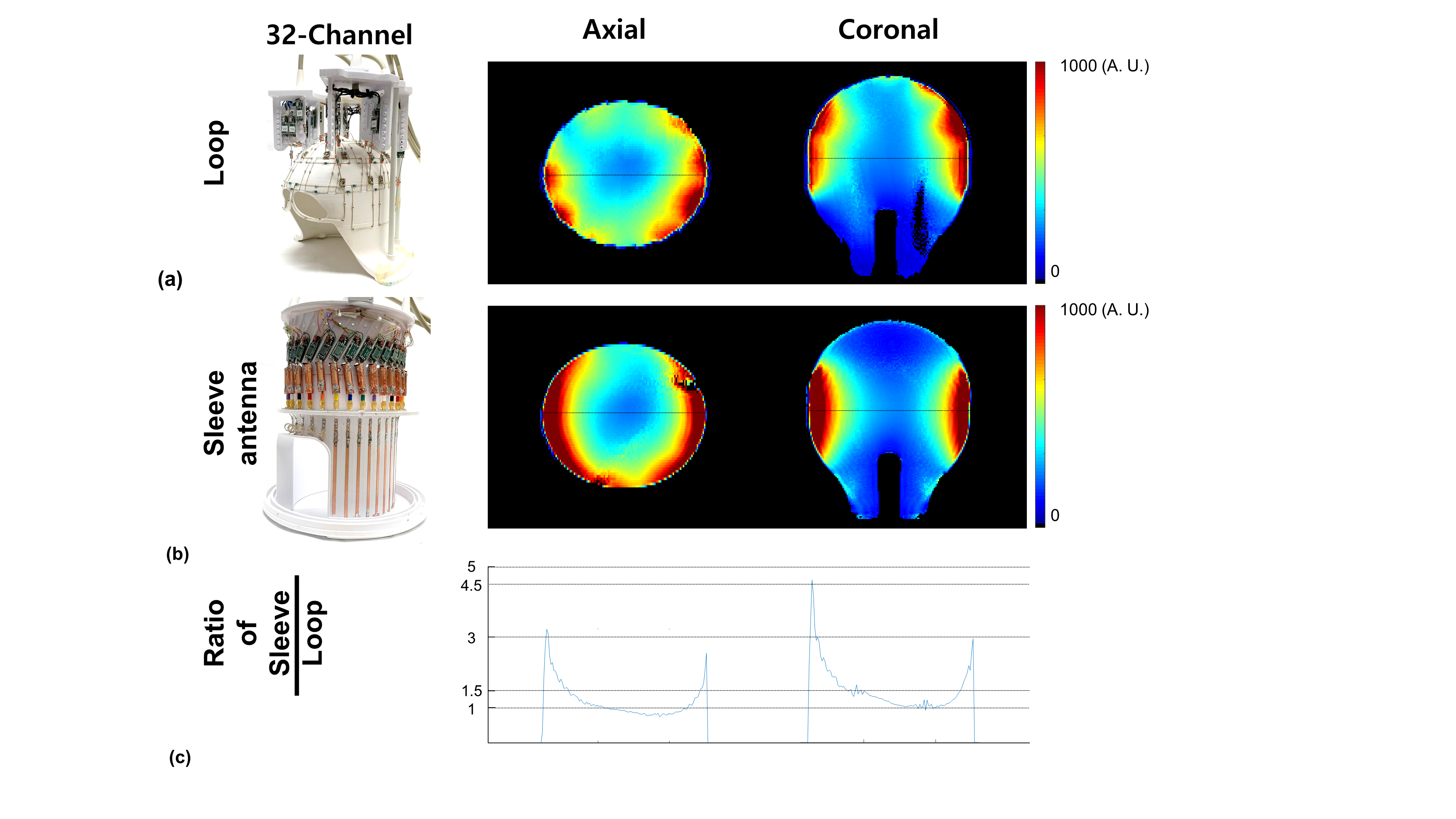
Results: We obtained and compared simulated SNR data of loop and sleeve antennas. For the same number of channels (1, 3, 5, and 32-channels), each SNR map was compared with similar imaging coverage. Our experimental data indicates an enhancement of SNR achieved with the 32-channel sleeve antenna array compared to the 32-channel loop array.
Impact: Our simulations indicate that a high-density sleeve antenna array compared to a classical loop array can achieve enhancement of SNR for human head imaging at 10.5T.
Introduction
Naturally, radiative antenna arrays present greater challenges in minimizing the mutual coupling between neighboring elements and consequently for high channel count arrays more robust decoupling approaches need to be developed. However, radiative antenna arrays with curl-free current modes make significant and dominant contributions to the ultimate intrinsic signal-to-noise ratio (UISNR) compared to loop arrays in the center of larger object at ultra-high frequencies (UHF) [1-2]. In our previous studies, the sleeve antenna concept with the associated end-fed structure showed a practical advantage due to the sleeve antennas collinearly aligned coaxial feed cable position [3-5]. Recently coaxial dipoles [6] were introduced by Budé et al as an elegant alternative to the fractionated dipole and similar benefits can be expected. Since the coaxial feed structure of a sleeve antenna receiver array can be outside the transmitter field, this arrangement has the potential to significantly reduce the interaction between the coaxial feed cables and the transmitter. To further reduce interaction in our previous work [3-5], we designed a sleeve antenna to utilize classical preamplifier decoupling techniques. With these prior established base technologies, we here attempt to further validate the achievable receive performance of loops compare to sleeve antennas for UHF MRI applications. For this, we arranged loops and sleeves to achieve similar imaging coverage and simulated for arrangements with the same number of channels (1, 3 &5) and evaluated the associated SNR maps. Then, we also experimentally compared intrinsic signal-to-noise ratio (iSNR) of the sleeve antenna array to those of a 32-channel loop receive array with a similar housing dimension at 10.5 T [5].Methods
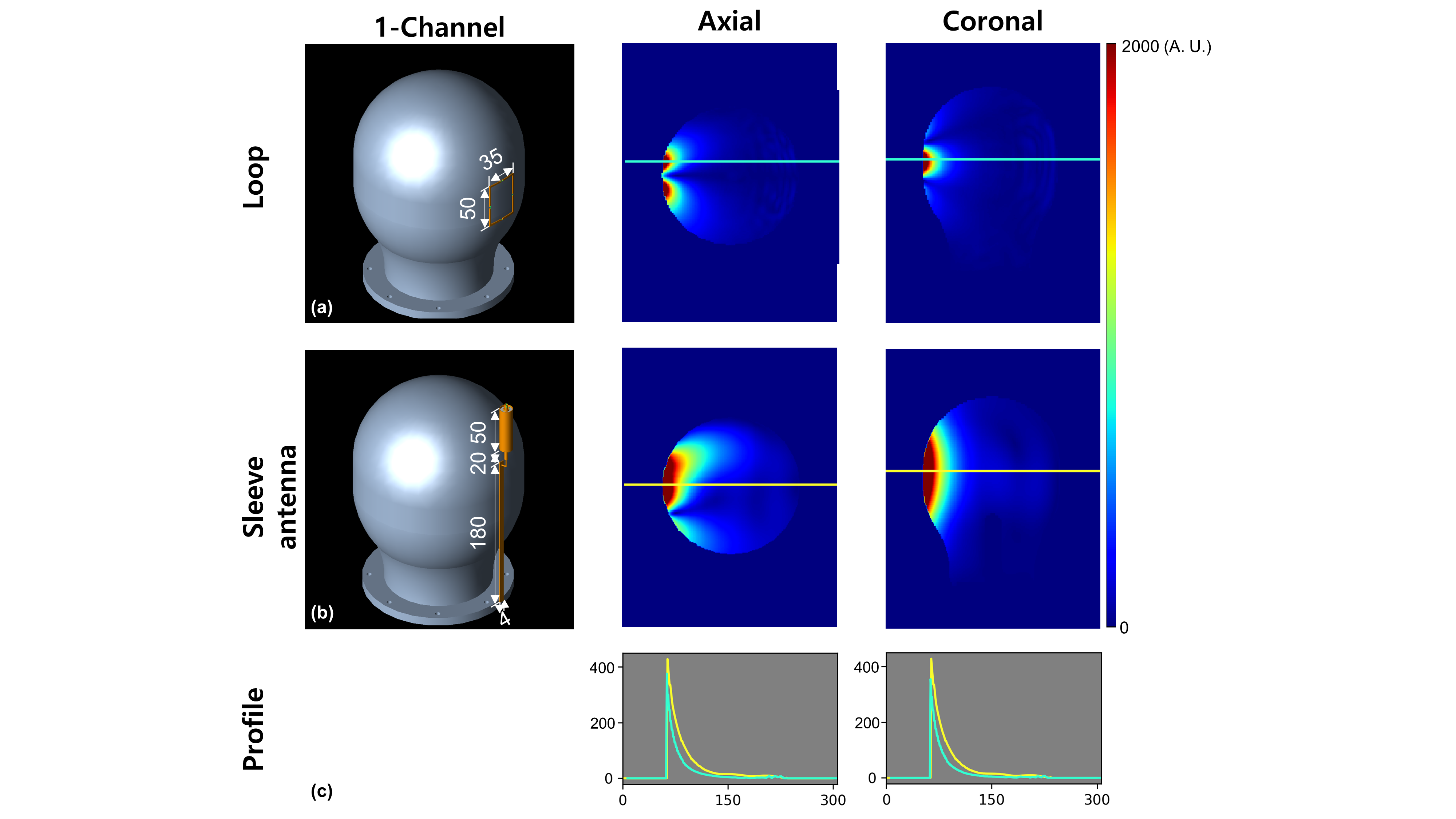
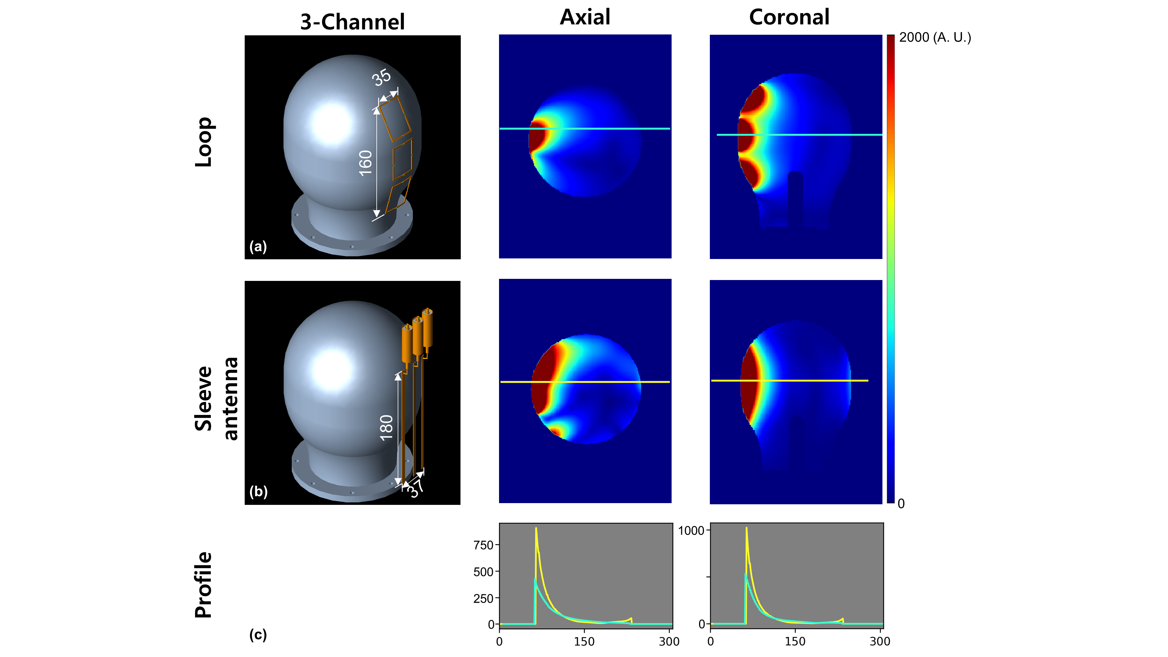
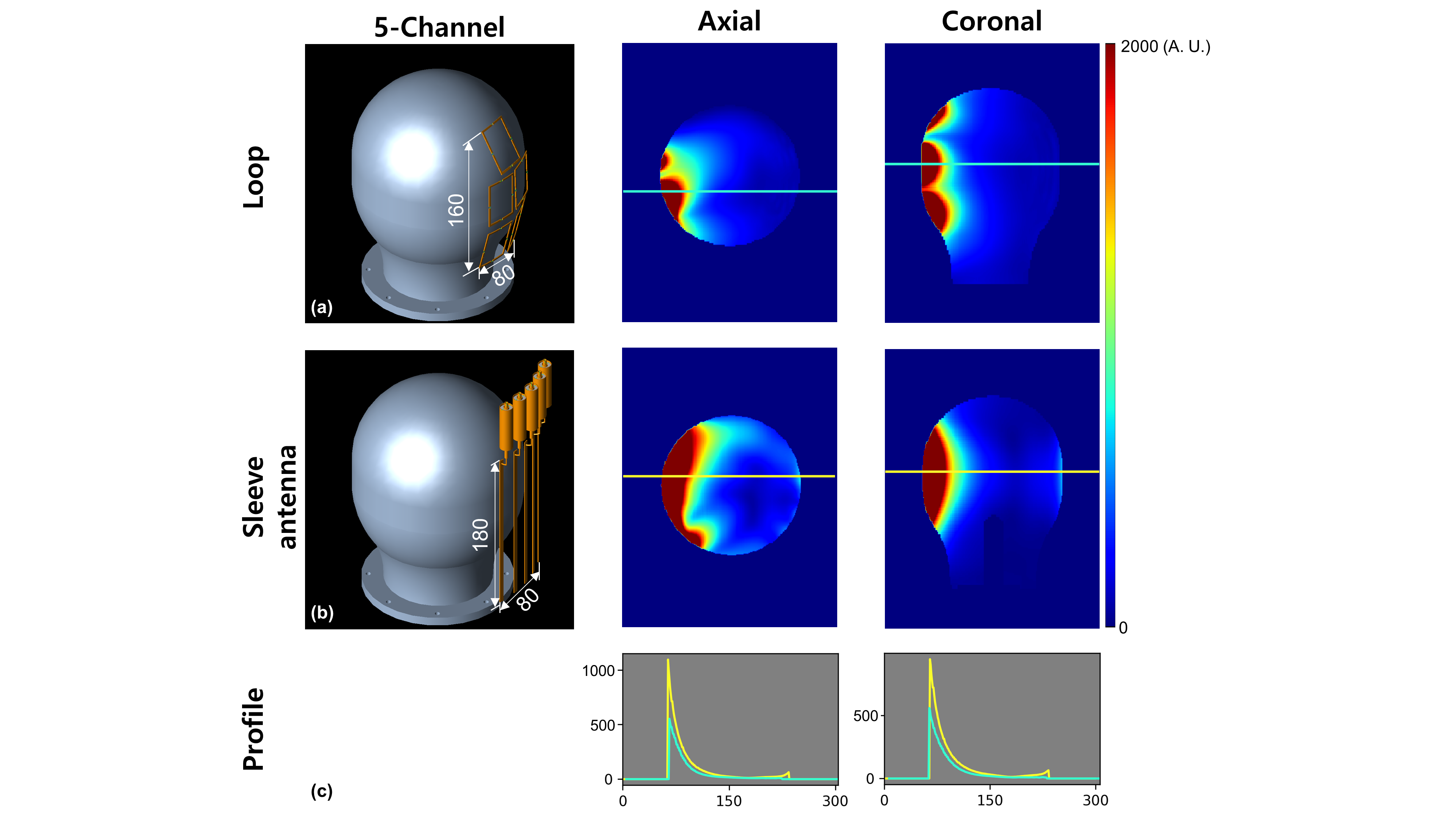
Simulated SNR maps were calculated using XFdtd (REMCOM, State College, PA) with 2 x 2 x 2 mm3 resolution. As shown in Fig. 1-3, 3D CAD renderings of the loop and sleeve antennas with 1, 3, 5-channels were evaluated, respectively. Each loop coil had the dimension of 35 × 50 mm2 [7] and the length of the individual sleeves was 180 mm with additional 70 mm for the required coaxial sleeve balun and detune structure. All SNR maps were calculated in MATLAB (Mathworks, Inc., Natick, MA, USA). These base elements were than evaluated in three loop configuration aligned in the z-direction and compared with the same number of the sleeve antenna arrays spaced 15 mm apart to achieve similar coverage. This was further extended to the five-channel case both for loops and sleeve antennas again in an arrangement which can achieve similar overall imaging coverage. Finally, to validate these simulation results we included the previous published experimental data of the 32-channel loop and sleeve antenna arrays from Woo et al. [5] as shown in Fig. 4. For SNR calculation, a proton-density gradient echo (GRE) sequence (TR: 4000 ms, TE: 3 ms, TA: 7:48 ms, nominal flip angle: 60◦ , FOV: 354 × 354, and resolution: 1.5 mm × 1.5 mm × 3 mm) was obtained to calculate the iSNR (Fig. 4) with the human shaped phantom at the isocenter of the magnet. The experimental iSNR maps were calculated with the 32-channel loop (Fig. 4a) and sleeve antenna (Fig. 4b) arrays using MATLAB. To calculate the SNR that would be produced by a homogenous 90 degree excitation, the iSNR maps were calculated from the GRE images by reconstructing the relaxed images in SNR units and correcting for locally varying excitation as measured by a flip angle map. For quantitative comparisons, the ratio of SNR of the 32-channel loop array over the 32-channel sleeve antenna array were calculated by MATLAB. The profiles of the ratio at the isocenter were drawn in Fig. 4c. FSL (FMRIB Software Library, Oxford, UK) was used for the proper registration.Results and Discussion
As shown in Fig.1., a single sleeve antenna shows 17% higher SNR in close proximity to the conductor compared to a loop. A boost in SNR performance was also observed with 3- and 5-channel sleeve antennas with an close gap (15 mm) between elements as is indicated in Figs. 2 and 3. As shown in Fig.2c and 3c, substantial SNR improvements are mostly associated with peripheral gains achievable with such closely coupled sleeve antennas in a higher density array arrangement. Our previously reported experimental data was included in Fig. 4 and similar shows peripheral SNR enhancement with a 32-channel sleeve antenna array compared to a 32-channel loop array.Conclusion
The sleeve antenna concept supports high-density receive antenna arrays and due to the higher conductor density this can result in a significant peripheral SNR gains.Acknowledgements
P41 EB027061, S10 RR029672, KMEDI hub under a Research grant Creative KMEDI hub in 2022 [No. B-C-N-22-10]; and in part by the Hankuk University of Foreign Studies Research Fund (of 2023)References
[1] Lattanzi, R. et al. Approaching ultimate intrinsic signal‐to‐noise ratio with loop and dipole antennas. Magnetic resonance in medicine 79, 1789-1803 (2018).
[2] Pfrommer, A. & Henning, A. The ultimate intrinsic signal‐to‐noise ratio of loop‐and dipole‐like current patterns in a realistic human head model. Magn Reson Med 80, 2122-2138 (2018).
[3] M. K. Woo et al., “Comparison of 16-channel asymmetric sleeve antenna and dipole antenna transceiver arrays at 10.5 Tesla MRI,” IEEE Trans. Med. Imag., vol. 40, no. 4, pp. 1147–1156, Apr. 2021.
[4] M. K. Woo et al., “A novel 16-channel transmitter/32-channel receiver combined sleeve antenna and dipole array for the human whole brain imaging at 10.5 Tesla,” in Proc. 30th Annu. Meeting ISMRM, Paris, France, 2020, p. 0708.
[5] M. K. Woo, et al, “A 32-channel Sleeve Antenna Receiver array for Human Head MRI Applications at 10.5 T”, IEEE Transactions on Medical Imaging, vol. 42, no. 9, pp. 2643-2652, Sep. 2023.
[6] L. Budé et al. “Using the end of the feeding cable directly as a flexible antenna at 7T: the coax monopole antenna” Proc. Intl. Soc. Mag. Reson. Med. 31 (2023) pg. 213
[7] Tavaf et al. “ A self-decoupled 32-channel receive array for human-brain MRI at 10.5 T “, Magn Reson Med. 2021;86:1759–1772
Figures