1447
Design and Construction of Integrated MC/RF Hardware for MRI of the Human Brain1Biomedical Engineering, Columbia University in the City of New York, New York, NY, United States, 2Department of Radiology, Columbia University Medical Center, New York, NY, United States, 3Columbia Magnetic Resonance Research Center, Columbia University in the City of New York, New York, NY, United States
Synopsis
Keywords: RF Arrays & Systems, RF Arrays & Systems, RF Rx array, Hybrid RF and shimming, Multi-coil shimming
Motivation: Multi-coil (MC) B0 shimming provides unrivaled brain shimming, yet early proof-of-concept implementations with preexisting RF hardware suffered from coupling and reduced sensitivity.
Goal(s): The design and realization of integrated MC/RF hardware for dynamic MC technique (DYNAMITE) B0 shimming of the human brain at 3T at full RF sensitivity.
Approach: We experimentally validate previously derived theoretical strategies for the minimization of MC-to-RF coupling and design integrated MC/RF hardware for MRI of the human brain.
Results: Great agreement was found between direct coupling measurements and simulated magnetic field flux, which was used in our previous work as a proxy of coupling due to mutual inductance.
Impact: Once the hardware construction and implementation with clinical MRI protocols is complete, the novel MC/RF setup is expected to improve diagnostic imaging in brain areas suffering from inhomogeneous B0 conditions.
Introduction
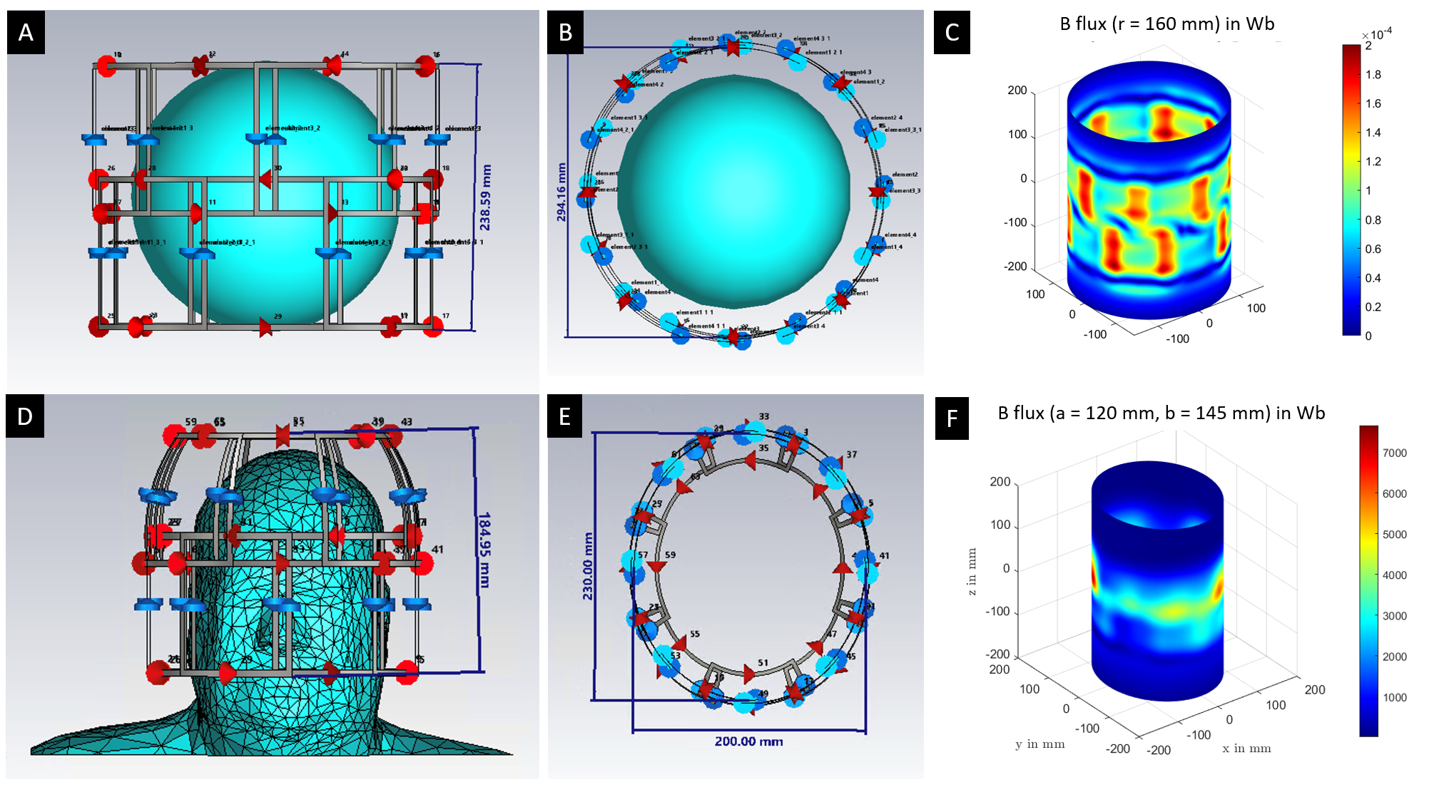
Multi-coil (MC) B0 shimming has been shown to allow unrivaled B0 uniformity across the human brain1,2. We previously presented the theoretical integration and concomitant design of MC and radio-frequency (RF) hardware for MRI of the human brain3,4. We presented simulations showing that MC and RF elements can be decoupled and thus sensitivity loss can be mitigated with a combination of strategic coil geometries / placement in addition to the use of electronic RF decoupling strategies. Specifically, we investigated a single-simulation method to guide the placement of MC elements around the RF coil in order to minimize MC-to-RF coupling due to mutual inductance which could potentially cause SNR loss. The flux of the magnetic field generated by the RF array through a variety of surfaces surrounding the array was calculated from simulated B fields. The B flux was then sampled using a 50-mm circular mask and multiplied by 40 turns. These flux maps were used as a proxy for MC-to-RF coupling to guide MC coil placement.In this work we (a) validated this approach in a single-coil setup and (b) present an up-to-date RF coil design for an integrated MC/RF system for brain imaging.
Methods
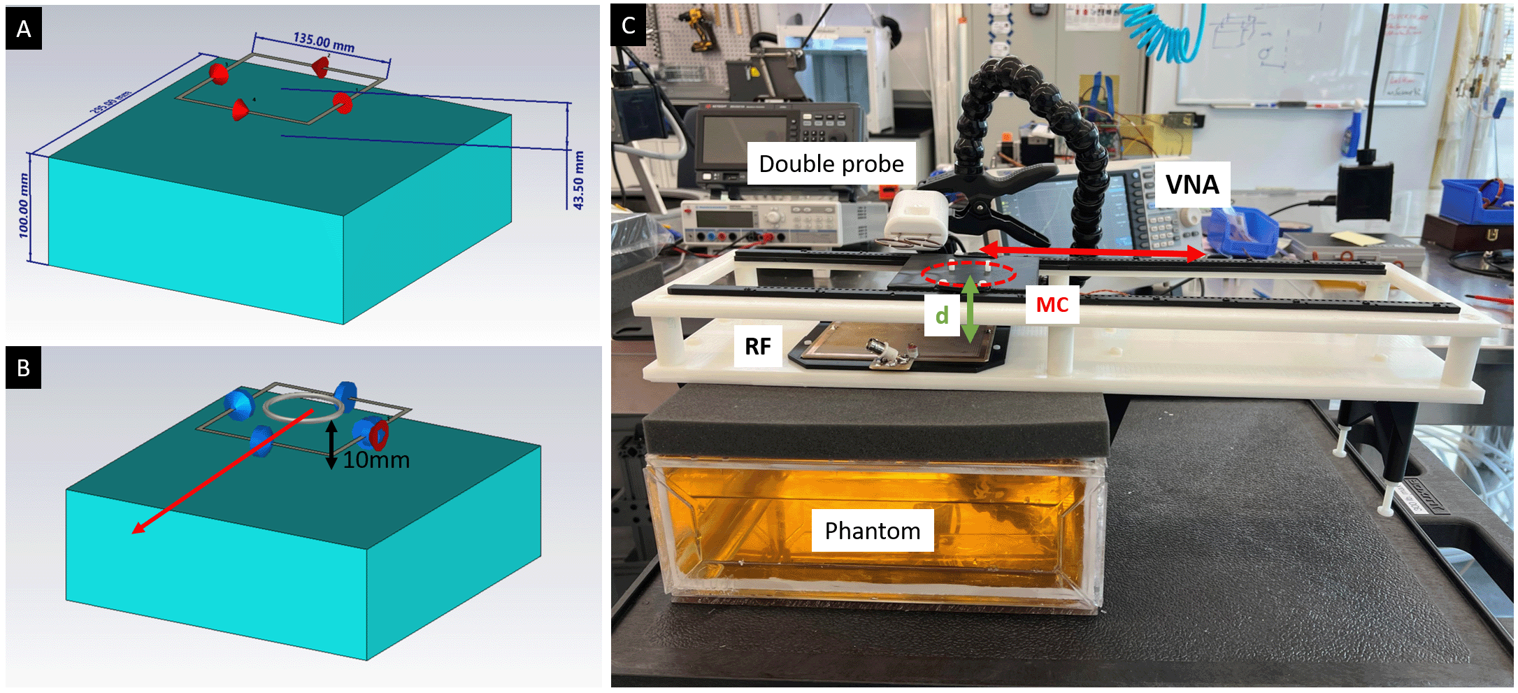
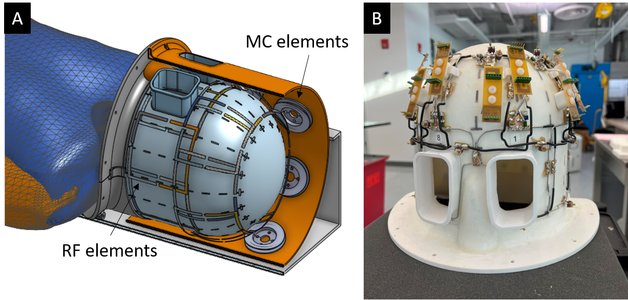
Experimental validation. In order to validate the magnetic flux approach for decoupling, three sets of experiments were carried out: (a) A single loop (135x135 mm) was simulated (Fig. 2A). The flux of the magnetic field generated by the loop through three planes distancing 10, 20 and 30 mm from the coil were calculated. (b) The same loop was simulated along with a passive MC placed at distance 10 mm (Fig. 2B). Various offsets between the two elements were simulated. For each offset, S11 and center frequency were recorded. (c) The simulated setup in (b) was built and tested at the bench. A test rig was built to hold the RF coil and MC element (40 turns, 50 mm diameter) in place and guarantee repeatable measurements. The resonance frequency was measured using a double probe. RF coil simulations. The 16-channel helmet array in Fig.1D-E was simulated and SNR was calculated5. The 16 elements were distributed in two rows of 8. Nearest neighbors were decoupled via overlap, except for the two frontal elements of the bottom row, which were decoupled capacitively to allow enough space for eye openings. The coil was loaded with a head model (εr=64 and σ=0.46 S/m, average white and gray matter at 123 MHz). RF coil construction. The simulated 16-channel helmet was built and tested at the bench (Fig. 5).Results
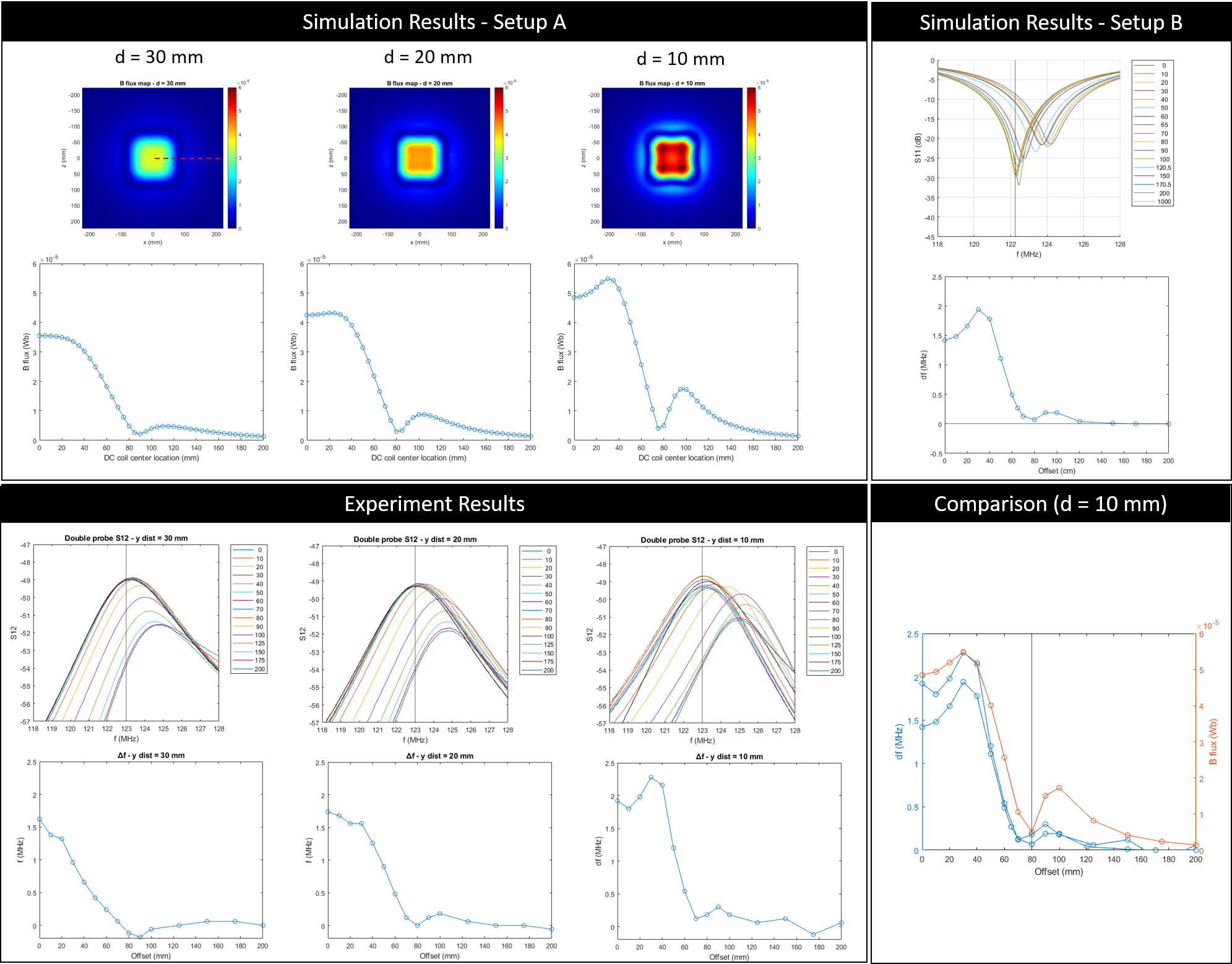
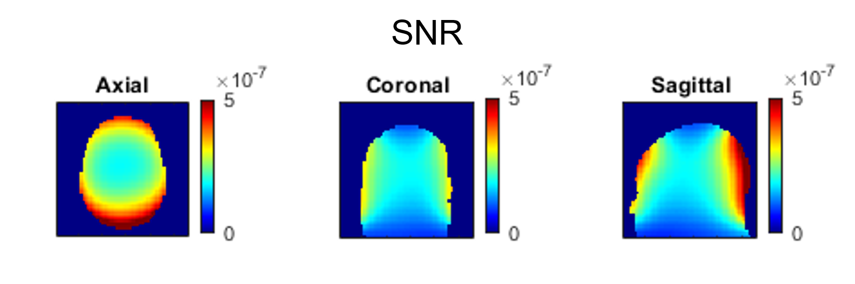
The results of the experimental validations are shown in Figure 3. For setup A the magnetic flux through the three planes (d = 10, 20, 30 mm) is shown. In all cases flux has a minimum when the MC element is placed with a 80 mm offset from the RF loop. For setup B the S11 at the feeding port and the resonance frequency over the coils offset is shown. The coupling between the elements results in a shift in resonance frequency, which is captured in the S11 measurement. In the experimental setup a similar trend is observed for the resonance frequency. The results of all three setups are compared for the case d = 10 mm in the bottom-right panel of Fig.3. Notably, in all cases the coupling (as either frequency shift or magnetic flux) peaks at 40 mm offset and is minimal at 80 mm, which represents the optimal overlap.The simulated SNR of the helmet array is shown in Figure 4. As expected the SNR is highest near the periphery and decreases towards the center of the head.
A photograph of the array is shown in Figure 5. The Q-ratio of a representative element was 7.8. The decoupling among nearest neighboring elements was S12<17dB.
Discussion
We present the design and realization of integrated MC/RF hardware for dynamic MC technique (DYNAMITE) for state-of-the-art B0 shimming of the human brain at 3T at full RF sensitivity. Great agreement was found between direct coupling measurements and simulated magnetic field flux as a proxy of coupling due to mutual inductance. The engineering of a dome-shaped design tailored to the human head is presented along with its partial construction.Next steps involve the implementation and calibration of the MC elements for B0 shimming as well as the comprehensive experimental validation of the system’s RF and B0 shim performances. Once the clinical MRI sequences and protocols have been adapted to allow DYNAMITE B0 shimming, the novel MC/RF setup is expected to improve diagnostic imaging of the brain.
Acknowledgements
This research was supported by the National Institute of Biomedical Imaging & Bioengineering (NIBIB) of the National Institutes of Health under award number R01-EB030560, and was in part performed at the Columbia MR Research Center.References
1. Juchem C, Nixon TW, McIntyre S, Boer VO, Rothman DL, de Graaf RA. Dynamic multi-coil shimming of the human brain at 7 T. J Magn Reson 2011;212:280–288.
2. Stockmann JP, Witzel T, Keil B, et al. A 32-channel combined RF and B0 shim array for 3T brain imaging. Magn Reson Med 2016;75:441–451.
3. Ianniello C, Theilenberg S, Majumder J, Vaughan JT, Juchem C. A 16-channel MC and RF hybrid system for B0 shimming and B1 reception: a preliminary prototype. Proc ISMRM 2023, p. 4430.
4. Theilenberg S, Ianniello C, Igwe KC, Brickman AM, Juchem C. Design Optimization of an Hybrid Multi-Coil Array for In Vivo Human Brain B0 Shimming. Proc ISMRM 2023, p. 4429.
5. Roemer PB, Edelstein WA.; Hayes CE; Souza SP; Mueller OM, The NMR phased array. Magn.Reson. Med. 1990, 16(2), 192-225.
Figures