1440
3T 8-channel 13C/1H TxRx array for hyperpolarized and steady-state 13C MRSI1Advanced Imaging Research Center, UTSouthwestern Medical Center, Dallas, TX, United States
Synopsis
Keywords: RF Arrays & Systems, RF Arrays & Systems, 3T 13C applications, low field transmit array design
Motivation: Tackle the coupling issue among the coil elements in phased array design at low field, so as to use phased array as transceiver at low fields for good transmit efficiency, receive sensitivity profile, and acceleration performance.
Goal(s): Design and build a 3T 13C/1H 8-channel array for hyperpolarized 13C MRSI and steady-state 13C MRS after oral uptake of 13C labelled glucose
Approach: Use a novel cable trap decoupling mechanism to decouple the coil elements in the 3T 13C 8-channel array
Results: Workbench and experiment results show that the coil elements are decoupled very well with each other.
Impact: This innovative research on mitigating coil element coupling in low-field phased array designs empowers low-field MRI applications. Enhanced transmit efficiency, receive sensitivity and acceleration performance offer improved diagnostic quality, benefiting scientists, clinicians, and patients.
INTRODUCTION
Phased array (1) principle has been widely used as transmit and receive (TxRx) array designs at high and ultra-high field MRI systems (2,3). However, phased arrays have been rarely used as transmit coil design at low field due to the strong coupling among the coil elements, which exists not only between the adjacent coil elements, but non-adjacent coil elements. Such coupling can be mitigated through preamplifier decoupling mechanism in a receive array design. In a transmit array design, however, new decoupling mechanisms must be introduced to decouple the coil elements. In this work, we designed and built a 3T 8-channel 13C/1H TxRx array with a novel cable trap decoupling mechanism.METHOD
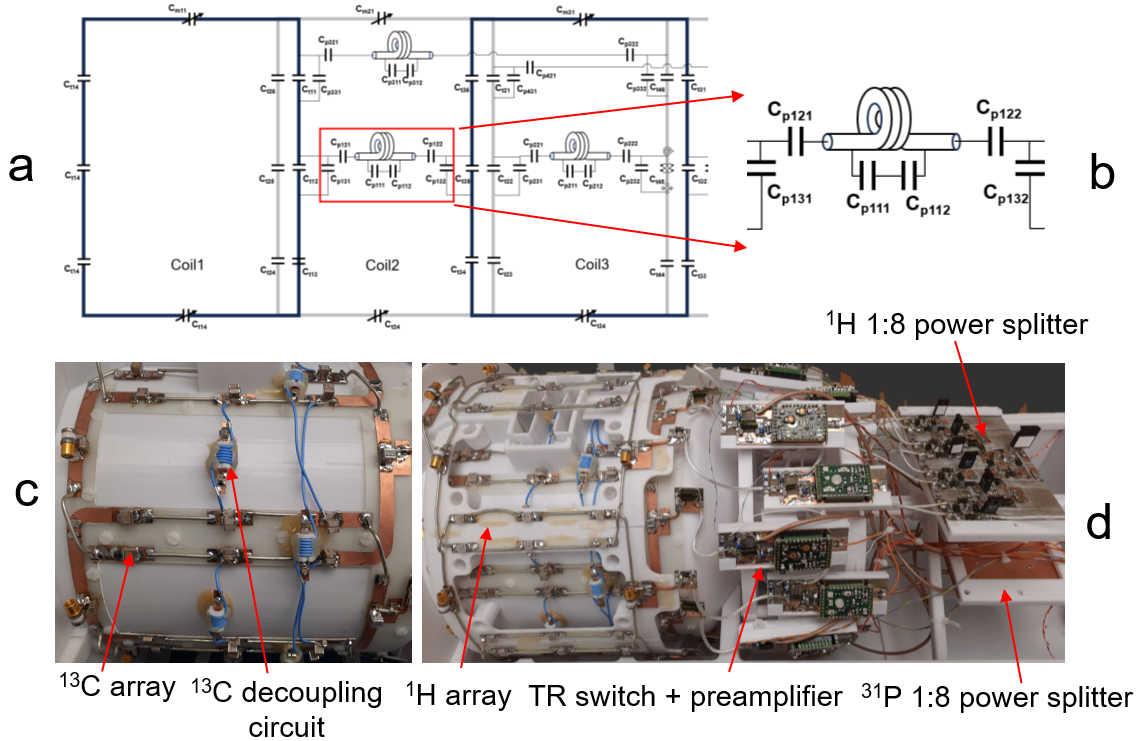
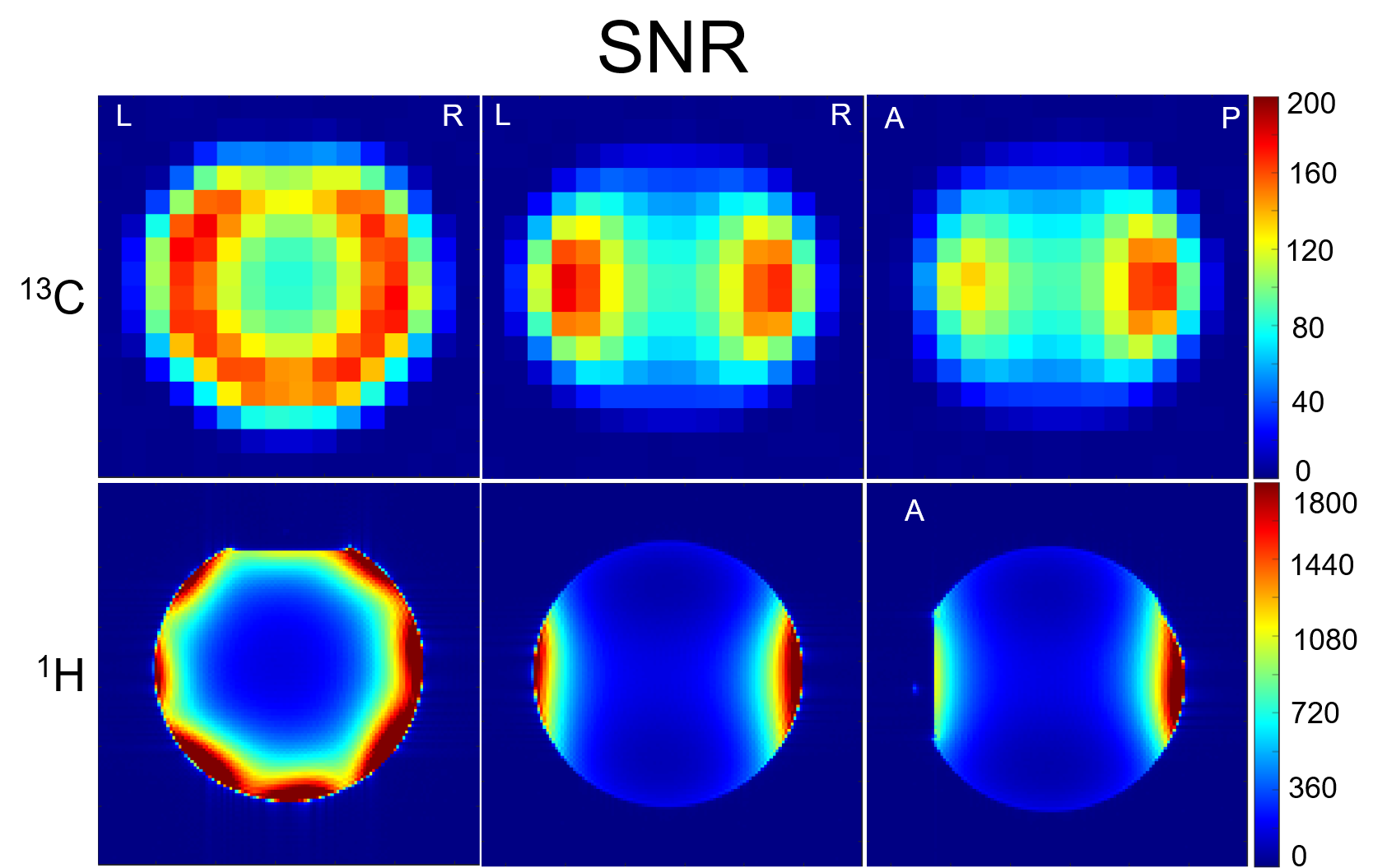
Coil Design: Figure 1a shows the schematic diagram of three 13C coil elements with cable trap decoupling circuits and Figure 1b shows the schematic diagram of the cable trap decoupling circuit only. Each cable trap decoupling circuit consists of an inductor (L) and capacitors Cpx11, Cpx12, Cpx21, Cpx22, Cpx31 and Cpx32 (x=1, 2, …, as their capacitance values may vary for different coil element decoupling). The cable trap is a parallel LC resonant circuit formed by an inductor, formed by 5 turns of 29-aug micro-coax wound on a 6 mm-diameter hollowed rod, and two capacitors (Cpx11, Cpx12, and Cpx11=Cpx12) placed at the two ends of a 5mm-wide PCB across the hollowed tube of the rod. The cable trap was placed at the middle point so that the length of the coax cable to the two coil elements to be decoupled is the same, as shown in Figure 1c. The eight 165mm × 113mm 13C coil elements were sitting on a 230mm-diameter cylinder, with the nose part raised up by 15mm. Adjacent coil elements were decoupled with each other by optimizing their geometric overlap. Cable trap decoupling circuit was used to decouple non-adjacent coil elements (coil 1 vs. coil 3, and coil 1 vs. coil 4). Eight 145mm × 120mm 1H coil elements (Figure 1d) were placed on a 260mm-diameter cylinder. The 13C and 1H arrays were co-centered and had 45° offset with each other in XY plane. Adjacent coil elements were decoupled by optimized geometric overlap. Each coil element was connected to its own TR-switch and preamplifier. Cable length was adjusted for preamplifier decoupling. 13C and 1H 1:8 power splitters were used to split the 13C and 1H transmit powers into 8 with 45° offset respectively. Phantom Experiment: SNR was measured in a spherical ethylene phantom to characterize the performance of the 13C and 1H arrays spatially. For 13C, a 2D CSI sequence with/without RF excitation was used to calculate SNR voxel-by-voxel by dividing the peak absolute signal by the standard deviation of noise; for 1H, SNR maps were reconstructed from two GRE sequences with and without RF excitation (4). Proton decoupling performance was evaluated by using the same 2D CSI sequence with and without proton decoupling. In vivo Experiment: Human subject studies were performed following a protocol approved by our institutional review board, and informed consent was obtained from subjects. In vivo 1H head imaging was acquired with 3D MPRAGE and FLAIR sequences. All scans were performed on a Siemens Prisma 3T MRI system (Siemens Healthcare, Erlangen, Germany).RESULT AND DISCUSSION
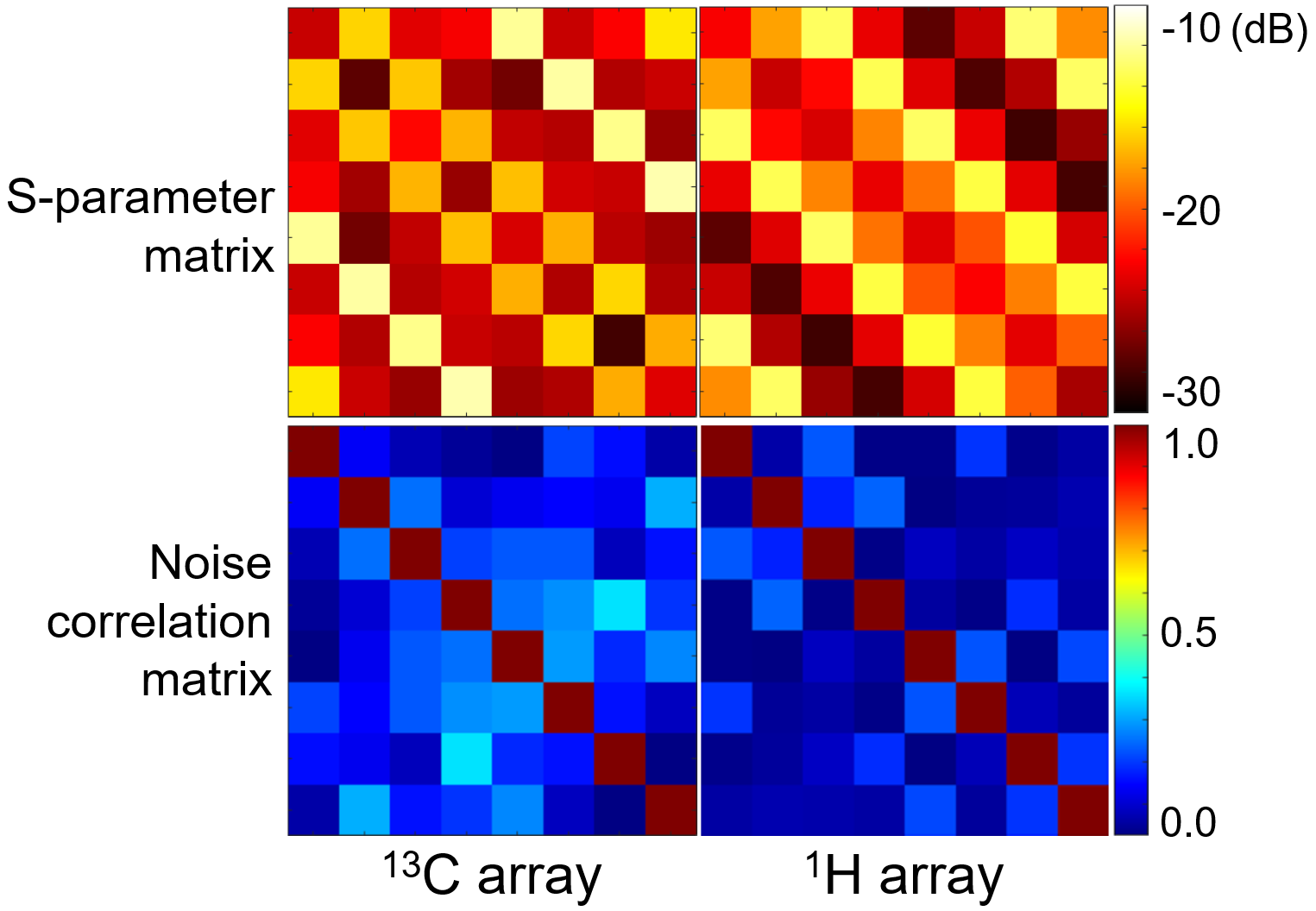
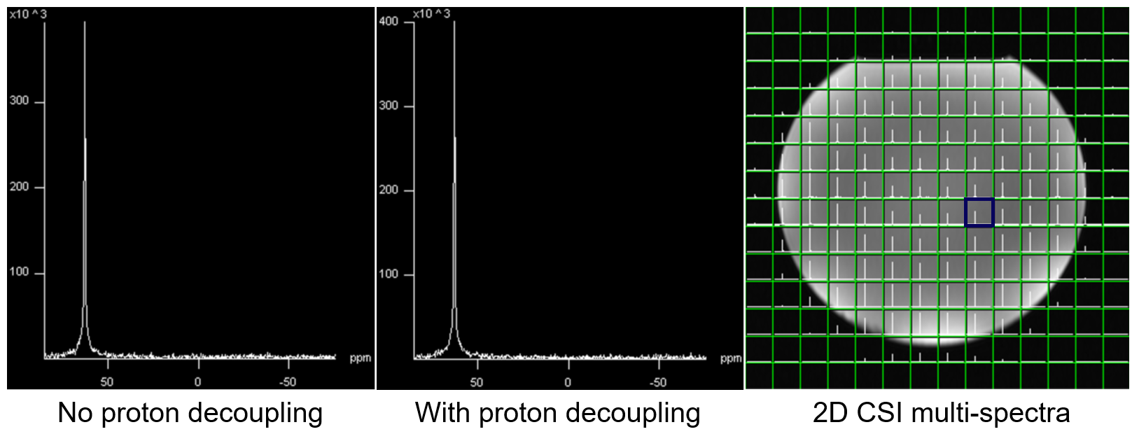
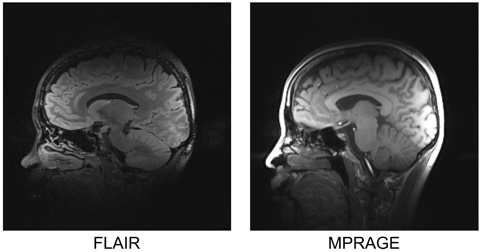
Unloaded to loaded Q ratio is 3.2 for the 13C coil element and 5.8 for 1H. Figure 2 shows the S-parameter matrices and the noise correlation matrix of the 1H and 13C arrays. The coil elements furthest to each other in the 13C array, e.g. coil 1 vs. coil 5, have the strongest coupling (max S21 = -11.6dB), as no decoupling mechanism was implemented between them. For the 1H array, all the S21 is lower than -13dB. Noise correlation matrices also showed that both arrays were well decoupled, with off-diagonal elements less than 0.35 in both. Figure 3 shows SNR maps of the 13C and 1H arrays. Both have higher signals in the peripheral area of the phantom. 13C spectra in the same voxel with/without proton decoupling shown in Figure 4 has no noise increase with proton decoupling, demonstrating sufficient decoupling between 1H and 13C. Figure 5 shows high-resolution head images acquired with the 3D FLAIR and MPRAGE sequences.CONCLUSION
We designed and built a 3T 8-channel 13C/1H array with cable trap decoupling mechanism. Workbench and experiment results show that the coil elements are decoupled very well with each other. We are testing 13C sequences to use this array for hyperpolarized 13C MRSI and steady-state 13C MRS after oral uptake of 13C labelled glucose.Acknowledgements
This work was funded by Cancer Prevention and Research Institute of Texas (CPRIT) RR180056 and was performed under the rubric of the Advanced Imaging Research Center, UT Southwestern Medical Center.References
1. Roemer PB, Edelstein WA, Hayes CE, Souza SP, Mueller OM. The NMR phased array. Magn Reson Med 1990;16(2):192-225.
2. Avdievich NI, Ruhm L, Dorst J, Scheffler K, Korzowski A, Henning A. Double-tuned (31) P/(1) H human head array with high performance at both frequencies for spectroscopic imaging at 9.4T. Magn Reson Med 2020;84(2):1076-1089.
3. Wang B, Zhang B, Yu Z, Ianniello C, Lakshmanan K, Paska J, Madelin G, Cloos M, Brown R. A radially interleaved sodium and proton coil array for brain MRI at 7 T. NMR Biomed 2021;34(12):e4608.
4. Kellman P, McVeigh ER. Image reconstruction in SNR units: a general method for SNR measurement. Magn Reson Med 2005;54(6):1439-1447.
Figures