1439
Geometry Matters: High Performance Acceleration with Twisted Pair and Conventional Coil Designs at 7T MRI1Electrical Engineering, Eindhoven University of Technology, Eindhoven, Netherlands
Synopsis
Keywords: RF Arrays & Systems, RF Arrays & Systems, g-factors
Motivation: Driven by the potential of the highly flexible twisted pair coil in creating unique sensitivity patterns for optimal acceleration.
Goal(s): To compare geometry factors of the twisted pair and conventional copper coils, exploring effective arrangements for various coil shapes.
Approach: Simulations of eight-element arrays containing circular and elongated coils; assessing geometry factors and the impact of random coil placements.
Results: Findings emphasize similar geometry factors between the twisted pair and conventional coils. Moreover, random coil setups around a phantom do not inherently improve geometry factors.
Impact: A comparison between twisted pair and conventional coils shows similar performance in g-factors. The flexibility of the twisted pair can be used to improve the g-factor but more work is required in finding the optimal shape of these coils.
Introduction
The configurations of RF coils play a significant role in parallel imaging [1]. To minimize noise amplification at high acceleration rates, it is essential to pursue geometry (g) factors that are as low as possible. In some studies, the various coil geometries and coil positionings were investigated in terms of minimized g-factor [2-5]. This study compares the g-factors simulated in eight-channel arrays containing twisted pair transmission line coils [6,7] and conventional loops, examining both circular and elongated shapes. Furthermore, it investigates the potential improvements in the g-factor achievable by adjusting the adaptable shape of the twisted pair coil to accommodate more intricate array topologies where each coil exhibits unique sensitivity patterns.Methods
The conventional loop coil was modelled with 1mm diameter copper wire. The twisted pair was modelled by twisting two 18 gauge PTFE insulated wires (see Fig. 1). Both coils had a diameter of 100mm and were tuned and matched to 297.2MHz. Eight coil elements were symmetrically arranged around a homogeneous cylindrical phantom (diameter=150mm, length=300mm, $$$\varepsilon_r$$$=67.9, $$$\sigma$$$=0.48S/m) at 15mm distance from the surface of the phantom. Electromagnetic simulations were conducted using CST Microwave Studio 2023 (Dassault Systèmes, France). SolidWorks (Dassault Systèmes SolidWorks Corporation, USA) was employed to create the intricate shapes of the twisted pair while ensuring a constant total coil length during shape modifications.The g-factor was calculated using equation (23) from [1]. To evaluate the g-factors from electromagnetic simulations, receive sensitivities were determined from the $$$B_1^-$$$ [8] and the noise correlation matrix $$$\Psi$$$ was derived from the real part of the impedance matrix [9,10]. The g-factor was calculated for 2D Cartesian parallel imaging with undersampling in the phase-encoding direction (left-right). The field of view (FOV) was a concentric square with a side length equivalent to the cylindrical phantom's diameter.
Results and Discussion
Fig. 2 displays the 1/g-factor maps for various acceleration factors (R=2-5) depicting both the conventional (b) and twisted pair (c) coils in circular (top row) and elongated (bottom row) shapes. Fig. 3 illustrates the maximum and mean values for the entire FOV, the periphery (75% of the phantom's radius), and the center (10% of the radius). Notably, the elongated shape demonstrates an enhanced g-factor, particularly noticeable at higher accelerations (R>3). The elongated loops exhibit a more evenly distributed g-factor, while the circular loops display a more concentrated pattern towards the center, evident in both the mean g-factors in the periphery and center.The improved performance of the elongated array could be attributed to the phase difference between non-overlapping coils [2], along with the more focused sensitivity profiles of the elongated coils [11]. Comparing the twisted pair and conventional coils indicates similar g-factors, with the twisted pair slightly outperforming the circular conventional coil, especially at higher accelerations (R≥4).
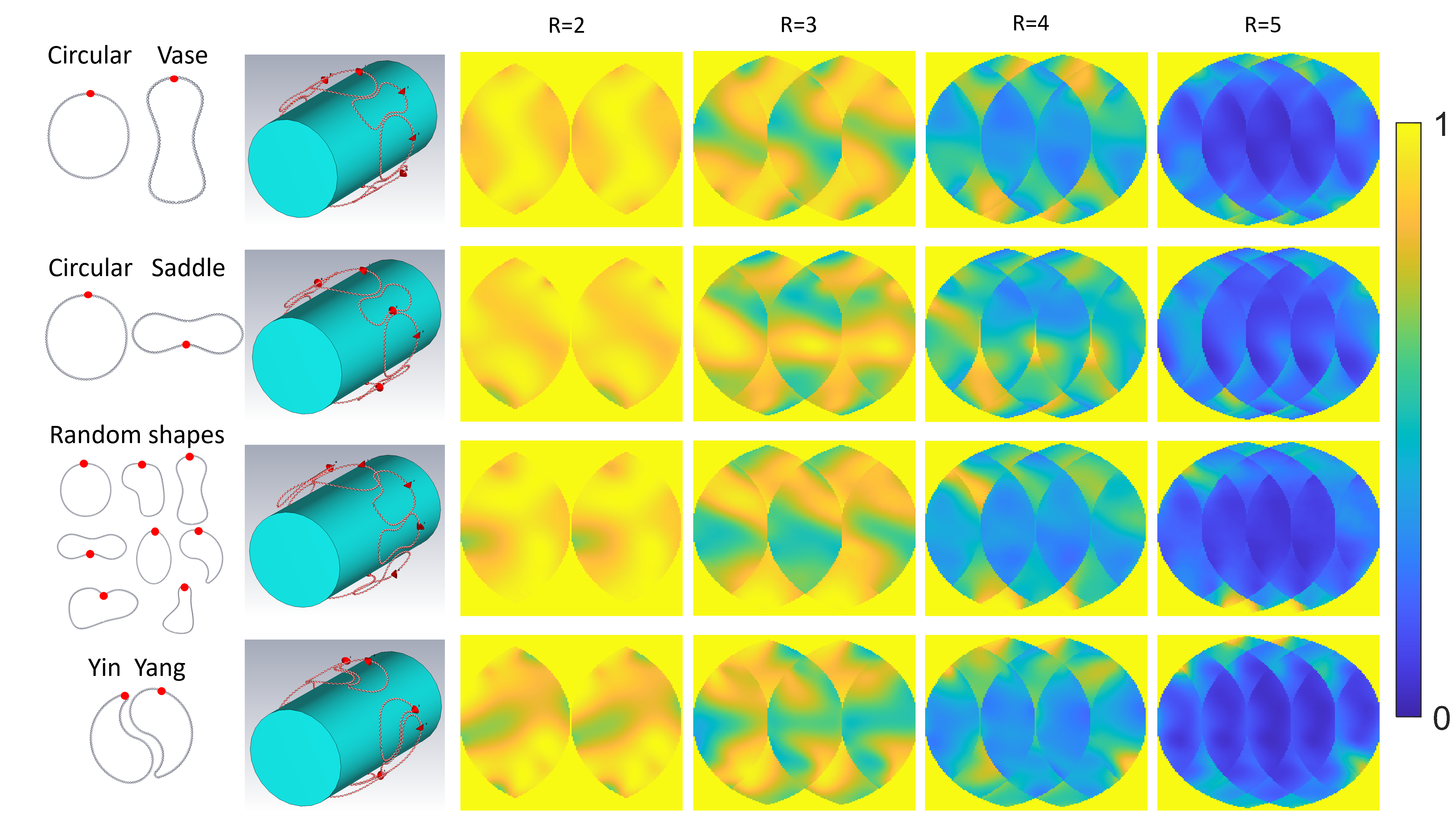
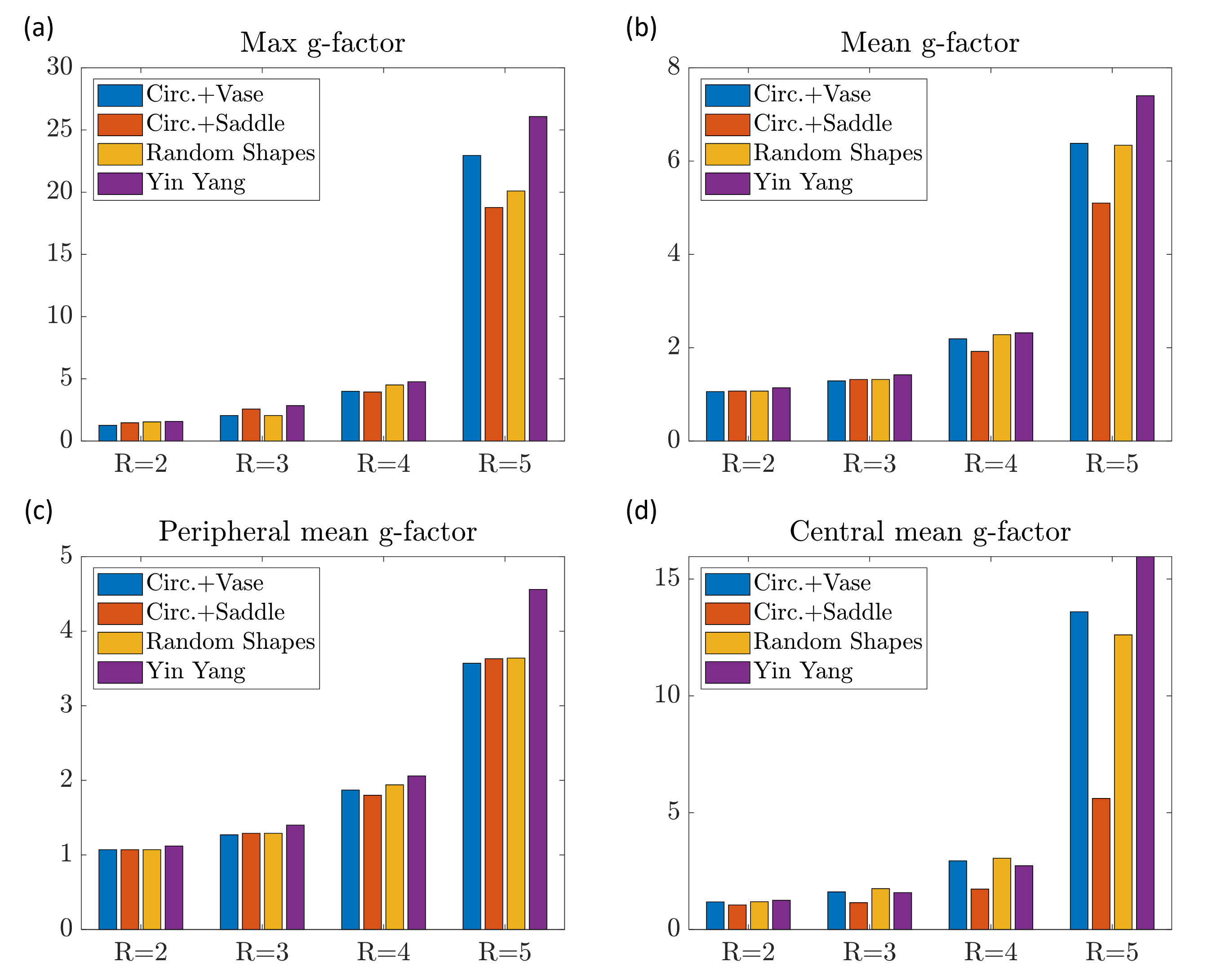
Fig. 4 presents the 1/g-factor maps for irregularly shaped coils, with corresponding maximum and mean values in Fig. 5. The circular and vase configuration, combining circular and elongated shapes, displays a blend of results observed in the circular and elongated 1/g maps (Fig. 2). However, it does not automatically improve mean and maximum g-factors compared to the conventional counterparts, which is observed across all four analyzed arrays. This underlines the importance of considering sensitivity pattern magnitude and phase distribution to maximize acceleration performance. The Yin Yang coil exhibits the poorest performance, likely due to substantial gaps between coil pairs causing signal voids. Investigating acceleration in the z-direction with these irregularly shaped coils, considering their shape changes in the z-direction, could potentially improve performance for more extreme array topologies [5,8].
Conclusion
Both the twisted pair and conventional coil exhibit comparable g-factor maps, whether in circular or elongated forms. Elongated arrays demonstrate superior g-factors at the periphery, while circular arrays show enhanced g-factors in the center. Employing random coil shapes around a phantom does not inherently result in improved g-factors; precise shape optimization of the coils is essential to achieve optimal performance.Acknowledgements
No acknowledgement found.References
[1] Pruessmann, K. P. et al. (1999). SENSE: sensitivity encoding for fast MRI. MRM, 42(5), 952-962.
[2] Weiger, M. et al. (2001). Specific coil design for SENSE: a six‐element cardiac array. MRM, 45(3), 495-504.
[3] Ohliger, M. A. & Sodickson, D. K. (2006). An introduction to coil array design for parallel MRI. NMR Biomed, 19(3), 300–315.
[4] Keil, B. & Wald, L. L. (2013). Massively parallel MRI detector arrays. JMR, 229, 75–89.
[5] Seeber DA et al. (2003). New RF coil topology for high performance SENSE in 3D. Proc. ISMRM (2003), Toronto, 465.
[6] Maravilla, J. A. et al. (2023). 15-Channel Head Cap Array using Twisted-Pair Elements for MRI. Proc. ISMRM (2023), Toronto, p 3733.
[7] Vliem, J., et al. (2023). Twisted Pair Transmission Line Coil -- A Flexible, Self-Decoupled and Extremely Robust Element for 7T MRI. https://arxiv.org/abs/2306.08934v2
[8] Nikulin, A. V. et al. (2023). Reconfigurable dipole receive array for dynamic parallel imaging at ultra‐high magnetic field. MRM. 90(4): 1713-1727
[9] Avdievich, N. I. et al. (2022). A 32-element loop/dipole hybrid array for human head imaging at 7T. MRM, 88(4), 1912–1926.
[10] Roemer, P. B. et al. (1990). The NMR phased array. MRM, 16(2), 192–225.
[11] Güler, S.,at al. (2022). Shielded Coaxial Cable Coils: the array configuration for maximized central SNR at 7T MRI. Proc. ISMRM (2022), London, p 1449.
Figures
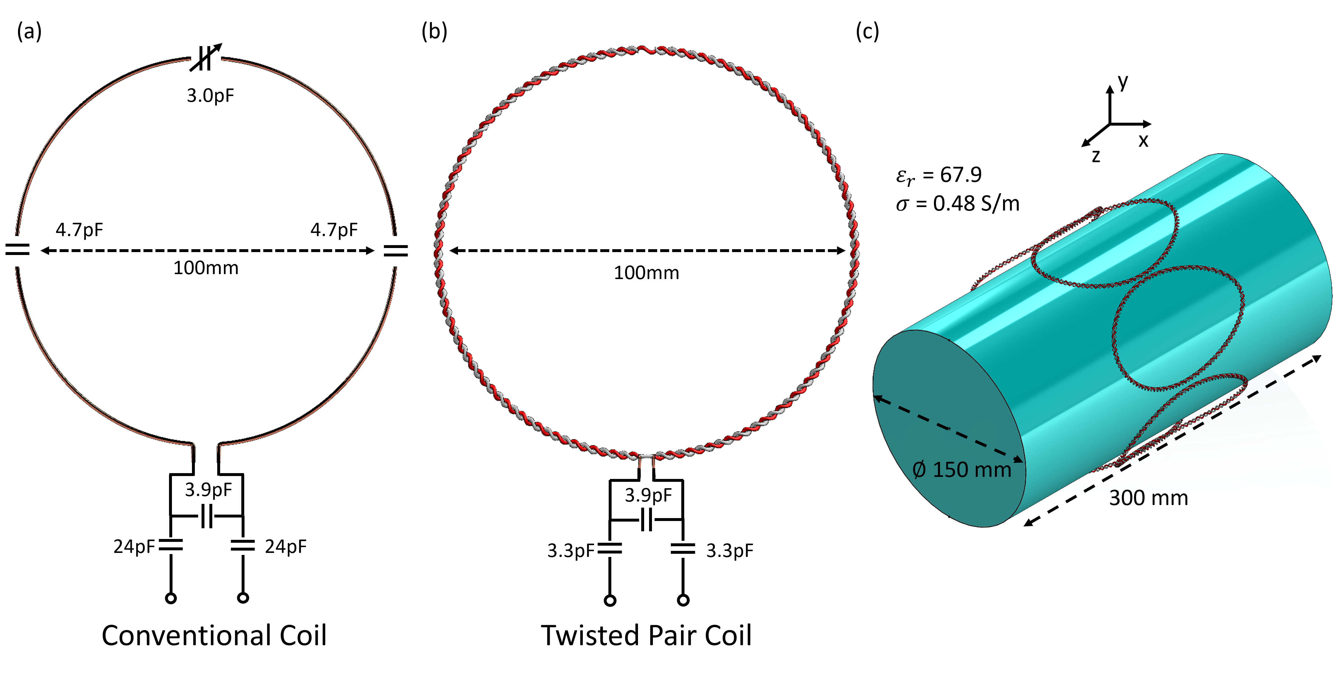
Fig. 1 RF coil simulation setup. (a) Conventional copper loop with distributed capacitors. (b) Twisted pair coil made by twisting two PTFE insulated 1mm thick wires (c) Simulation setup: homogeneous cylindrical phantom and eight elements array.
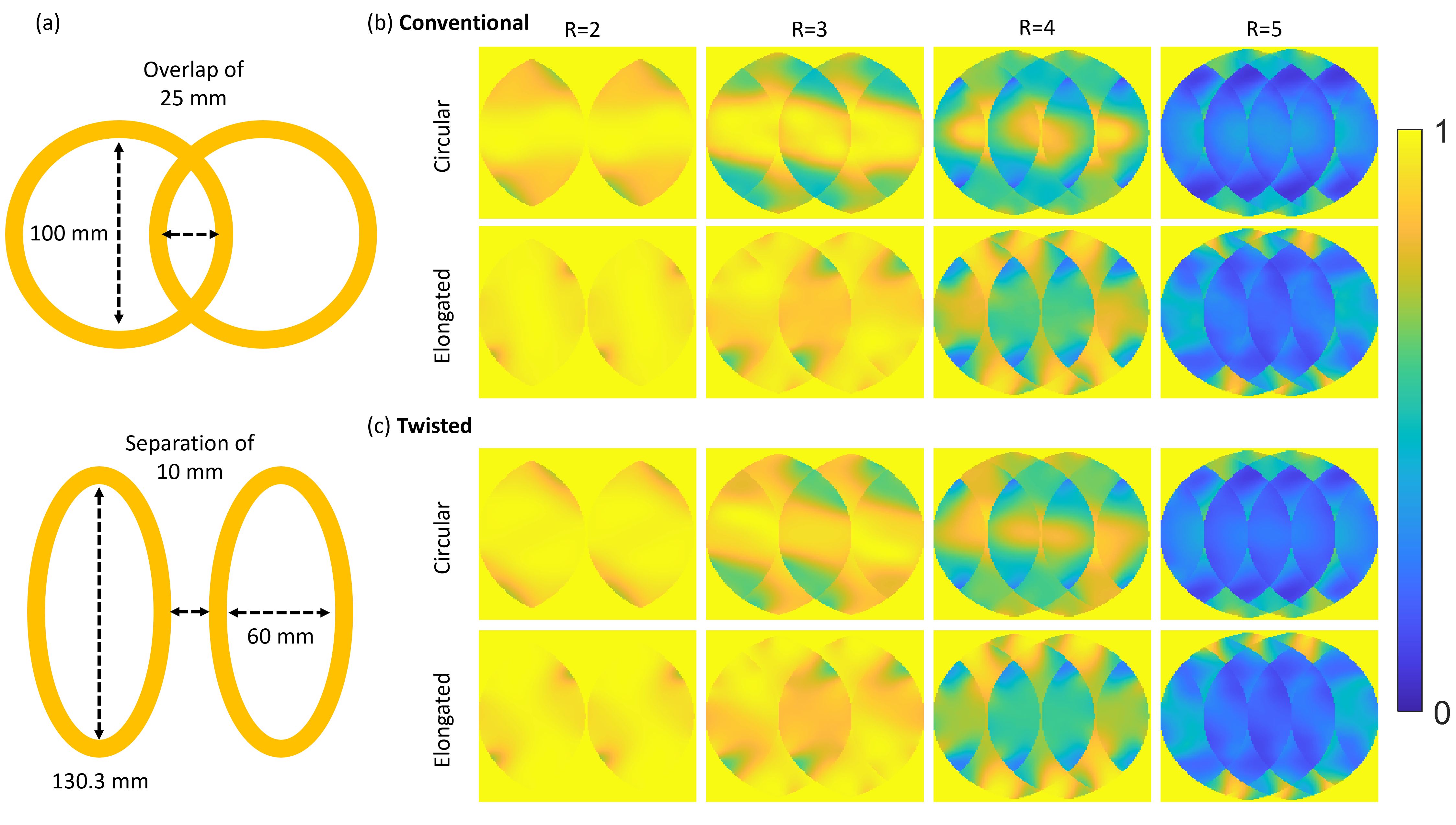
Fig. 2 1/g-factor maps for simulated accelerations (R=2-5). Eight-element arrays containing circular and elongated conventional and twisted pair coils. (a) schematic of the circular (top) and elongated (bottom) forms of the coils. (b) & (c) Circular (top) and elongated (bottom) 1/g maps of the conventional and twisted pair coil, respectively. Higher 1/g is better.
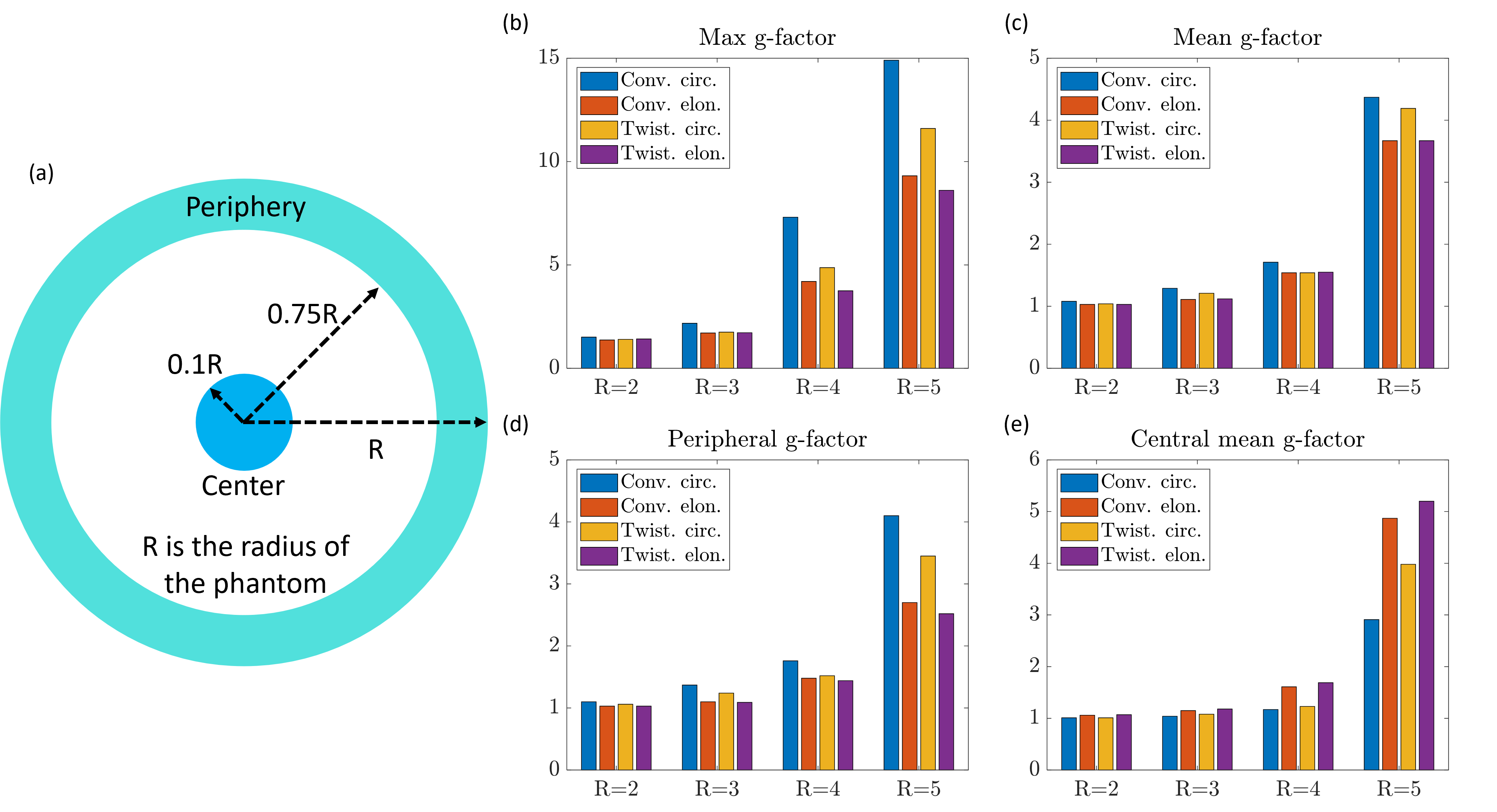
Fig. 3 Max (b) and mean (whole (c), periphery (d) and center (e) of the phantom) g-factors of the conventional and twisted pair coil in a circular and elongated shape, with an illustration of the defined areas in the phantom (a). Lower g-factor is better.