1438
A 6-dipole preamplifier-decoupled parallel-transceive array with a 16-loop receive array for NHP brain imaging at 7 T.1Cognitive Neuroimaging Unit, INSERM, CEA, Université Paris-Saclay, NeuroSpin Center, GIF-SUR-YVETTE, France, 2BAOBAB, Université Paris-Saclay, CEA/Joliot/NeuroSpin, GIF-SUR-YVETTE, France
Synopsis
Keywords: RF Arrays & Systems, High-Field MRI, non-human primate, RF antenna, Dipole
Motivation: Imaging the brains of non-human primates (NHPs) at ultra-high field (UHF) is challenging, especially for whole-brain functional imaging in awake NHPs where high SNR is needed.
Goal(s): To design a dedicated system that overcomes challenges associated with UHF imaging and enhances signal-to-noise ratio (SNR) for high-quality NHP brain imaging.
Approach: We developed a 6-dipole parallel-transceive array, and a 16-loop receive array, optimized through electromagnetic simulations. We implemented preamplifier-decoupled dipoles to reduce coupling issues.
Results: The system showed good preamplifier-decoupling levels. Our dipoles’ implementation reduced experimental noise matching issues and EM simulations shows an SNR improvement.
Impact: Our 6pTx/22Rx antenna should improve awake NHP brain imaging at UHF, including transceive preamplifier-decoupled dipoles, designed for a specific imaging setup.
Introduction
Imaging the brain of non-human primates (NHPs) at ultra-high field (UHF) presents unique challenges, particularly when striving for whole-brain functional imaging of awake NHP. To achieve this goal, we designed an RF coil that fits with the mechanical constraints of an awake NHP setup and that is operable in conjunction with a B0 shim multi-coil array and magnetic field probes. For UHF imaging, studies have indicated that it is advantageous to incorporate transmit elements as transceivers into the comprehensive receive array structure (1). This integration can enhance the SNR and increase parallel imaging performance (2,3), while receive-only elements exhibit higher sensitivity near the periphery, transceiver coils show increased sensitivity in the central region (1). However, in volume restricted environment, coupling between nearby elements may appear, inducing a major challenge to match the impedance of each element simultaneously to the input impedance of the reception circuit. Then, a nonoptimal match degrade the preamplifier noise figure, which leads to a poor SNR (4). This coupling can also contribute to a low robustness over subject position and size. Moreover, the progress of parallel MRI methods (5-7) has strengthened the focus on decoupling and preserving the isolation of coils. In parallel imaging techniques, the sensitivity profiles of the individual coils should be as distinct as possible to effectively encode spatial information. Otherwise, it would result in lower-quality parallel MRI reconstructions(7-10). Here, we present a 6-dipole parallel-transceive array, together with a 16-loop receive array. Both dipoles and loops being placed inside an 18-centimeter diameter B0 shim. To prevent coupling with other dipoles and receive loops during the reception mode, the dipoles are preamplifier-decoupled.Methods
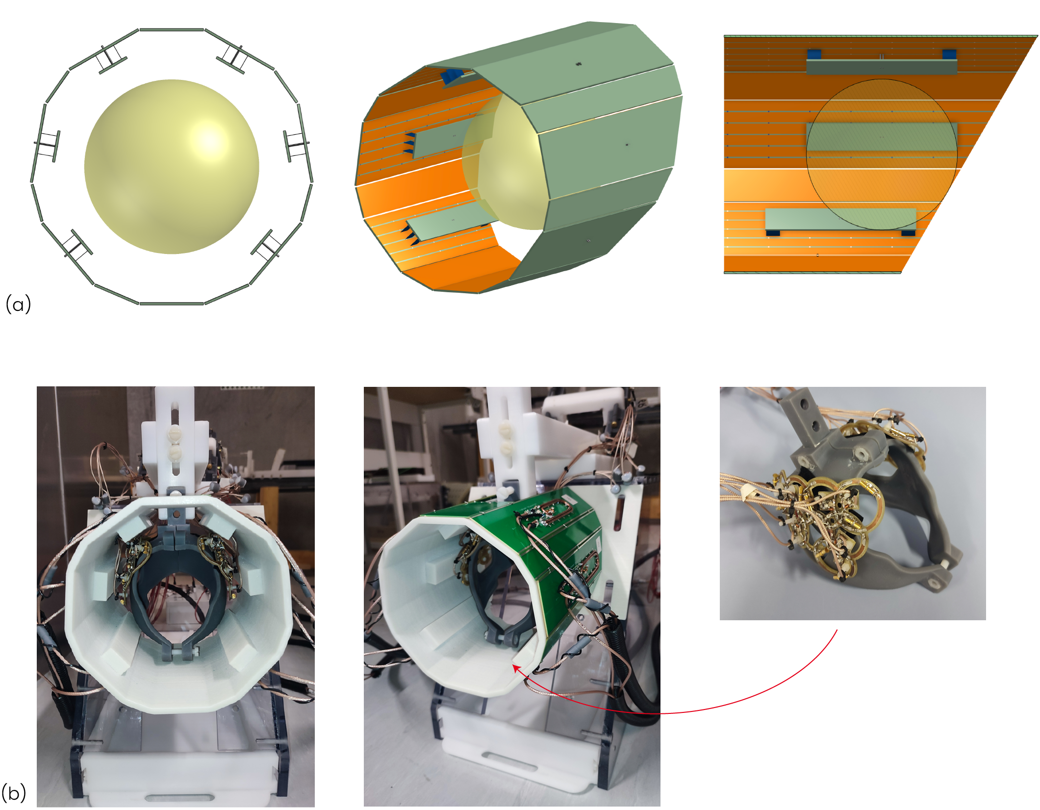
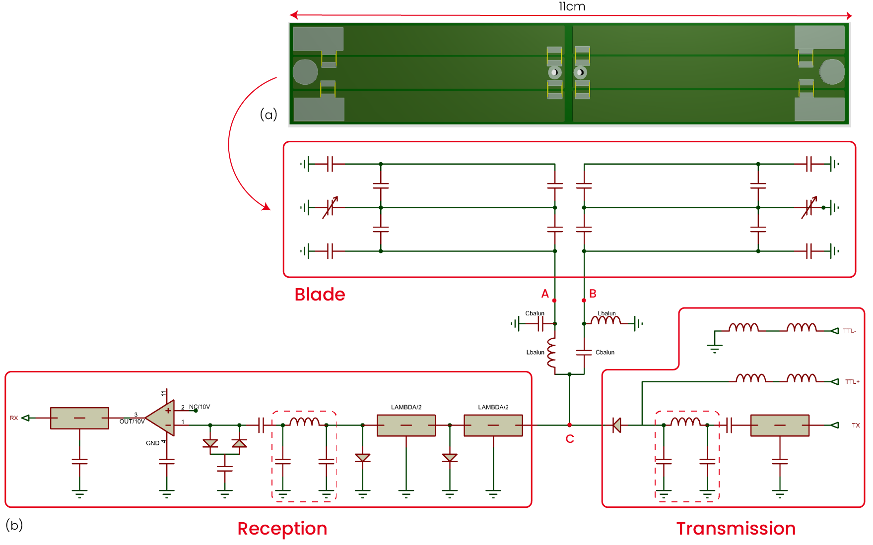
Eight loops are placed on each side of the NHP’s head. The loops are detuned during transmission mode using pin diodes circuits. To save space, the preamplifiers (WanTcom, Chanhassen, MN) are placed outside the coil, and cable traps are placed on the wires in-between the loops and their preamplifiers. The housing of the transceiver dipoles, designed to fit in a B0 shim array and with an awake NHP chair, is 17cm diameter and 22cm long. 6 transceiver dipoles are placed around the NHP head, the two lower dipoles are shifted along the z-axis. (Fig. 1) Electromagnetic simulations conducted using Ansys HFSS (Ansys, PA, USA) allowed to first optimize the dipole blade design to maximize the B1+ field strength and penetration depth over an 11-centimeter diameter phantom (sigma = 0.78 S/m and epsilon = 47). A 3-split 11-centimeter long and 10mm elevated blade design was chosen for its B1+ field strength and impedance low variability over the phantom position. Embedded circuit co-simulation in the Ansys Electronics Desktop suite helped in designing a circuit that ensures good impedance matching in both transmission and reception (Fig. 2). A lumped elements balun, tuned for 297MHz, is used as an impedance transformation circuit and becomes an element of current reduction in the blade in reception when the impedance brought back to point C (Fig 2b) by the lambda/4 line is really low. One impedance transformation circuit in transmission and one in reception allows to respectively power-match and noise-match the impedance to 50ohm.Results
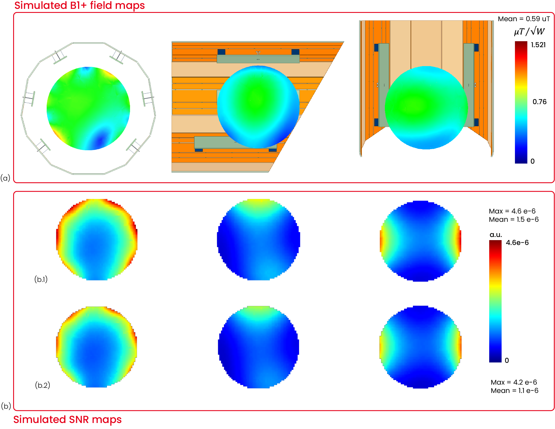
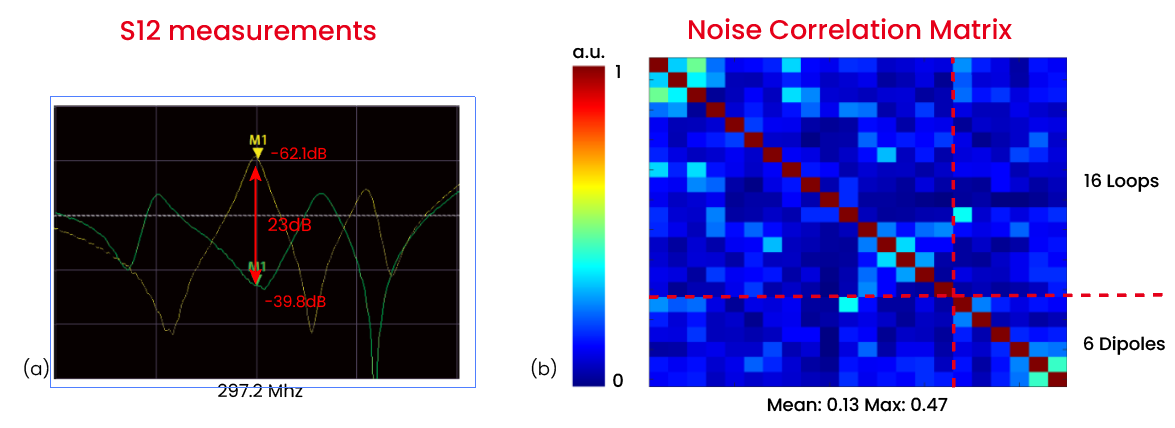
Experimentally, the 6 dipoles were tuned with four 4.6pF capacitors and two variable capacitors (range 0.8pF-8pF) (Fig. 2a) and matched in transmission at a maximum of –8dB. Fig. 3a shows simulated pseudo-circular polarization mode B1+ field, with a homogeneous field over the center of the phantom. For 1W of total injected power, maximum B1+ value is 1.52uT and mean value over the phantom is 0.59uT. b) Shows the simulated SNR maps for the 6 dipoles with and without preamp-decoupling. Preamp-decoupling offers a 25% mean SNR increase (1.5e-6 with preamplifier decoupling and 1.1e-6 without). For an optimized circular polarization mode Fig. 4a shows a S12 measurement using a double decoupled probe(11) near the dipole blade which reveals a 23dB difference between the preamp decoupled and non-decoupled cases. The noise correlation matrix Fig. 4b shows a similar noise correlation between loops and dipoles and can indicates the dipoles preamplifier decoupling efficiency.Conclusion
Our 6-dipole parallel-transceive array and a 16-loop receive array, specifically designed for awake NHP imaging shows good results experimentally. By implementing preamplifier-decoupled dipoles, we successfully reduced coupling issues and showed good decoupling levels. First in vivo tests are planned before 2024.Acknowledgements
We acknowledge the financial support of the French national research agency (ANR) under the reference ANR-20-CE37-0005 and the exploratory program of CEA, the French Alternative Energies and Atomic Energy CommissionReferences
[1] N. I. Avdievich et al., « A 32-element loop/dipole hybrid array for human head imaging at 7 T », Magnetic Resonance in Medicine, vol. 88, no 4, p. 1912‑1926, 2022, doi: 10.1002/mrm.29347.
[2] Avdievich, N. I., Giapitzakis, I. A., Bause, J., Shajan, G., Scheffler, K. & Henning, A. Double-row 18-loop transceive-32-loop receive tight-fit array provides for whole-brain coverage, high transmit performance, and SNR improvement near the brain center at 9.4T. (2019) Magn Reson Med 81, 3392-3405.
[3] Lagore, R. L., Moeller, S., Zimmermann, J., DelaBarre, L., Radder, J., Grant, A., Ugurbil, K., Yacoub, E., Harel, N. & Adriany, G. An 8-dipole transceive and 24-loop receive array for non-human primate head imaging at 10.5 T. (2021) NMR Biomed 34, e4472.
[4] Roemer PB, Edelstein WA, Hayes CE, Souza SP, Mueller OM. The NMR phased array. Magn Reson Med 1990; 16: 192–225.
[5] Sodickson DK, Manning WJ. Simultaneous acquisition of spatial harmonics (SMASH): fast imaging with radiofrequency coil arrays. Magn Reson Med 1997; 38: 591–603.
[6] Pruessmann KP, Weiger M, Scheidegger MB, Boesiger P. SENSE: sensitivity encoding for fast MRI. Magn Reson Med 1999; 42: 952–962.
[7] Griswold MA, Jakob PM, Heidemann RM, Nittka M, Jellus V, Wang JM, Kiefer B, Haase A. Generalized autocalibrating partially parallel acquisitions (GRAPPA). Magn Reson Med 2002; 47: 1202–1210.
[8] Weiger M, Pruessmann KP, Leussler C, Roschmann P, Boesiger P. Specific coil design for SENSE: a six-element cardiac array. Magn Reson Med 2001; 45: 495–504.
[9] Lee RF, Westgate CR, Weiss RG, Newman DC, Bottomley PA. Planar strip array (PSA) for MRI. Magn Reson Med 2001; 45: 673–683.
[10] de Zwart JA, Ledden PJ, Kellman P, van Gelderen P, Duyn JH. Design of a SENSE-optimized high-sensitivity MRI receive coil for brain imaging. Magn Reson Med 2002; 47: 1218–1227[11] H. Fujita, T. Zheng, X. Yang, M. J. Finnerty, et S. Handa, « RF Surface Receive Array Coils: The Art of an LC Circuit », Journal of Magnetic Resonance Imaging, vol. 38, no 1, p. 12‑25, 2013, doi: 10.1002/jmri.24159.
Figures