1437
The advantage of conventional loop coils without distributed capacitors – elongation for improved performance in 7T MRI1Department of Electrical Engineering, Eindhoven University of Technology, Eindhoven, Netherlands
Synopsis
Keywords: High-Field MRI, High-Field MRI, Flexible coils, SAR efficiency, Coupling, Non-uniform current distribution
Motivation: At Ultra-High-Field, non-uniform currents have the potential to boost efficiency of loop coils at depth. However, possible advantages of non-uniform current naturally arising from short wavelength at Ultra-High-Field have not been investigated yet.
Goal(s): To characterize the impact of non-uniform currents on SAR efficiency for different coil geometries and coil orientations relative to the main magnetic field, and evaluate the feasibility of using such coils
Approach: Analysis was performed using simulations and experiments
Results: A 62x280mm elongated loop provided higher SAR efficiency than a conventional loop, or a dipole, at depth, with flexibility. low coupling, similar SNR and transmit efficiency than a dipole.
Impact: An elongated design of loops provided higher performance than conventional loops and dipoles in terms of SAR efficiency at depth, with flexibility, and low coupling. Results in this work provide a new avenue to explore in flexible coil design.
Introduction
In conventional MRI loop coil design, uniform current distributions are obtained by placing multiple capacitors at equal intervals along the perimeter of the loop. Lately at 7T MRI, non-uniform current distributions have become topic of study, including redistribution of capacitor values1 or changing the capacitor positions2. Without capacitors, a $$$\geq$$$12cm diameter loop already exhibits a non-uniform current distribution. To exploit this effect, we characterized the impact of non-uniform currents on SAR efficiency for different coil elongations and orientations relative to the main magnetic field. Elongation optimization, flexibility -i.e. shape robustness- was also researched, as well as performance in an 8-channel array configuration on top of / near a body-mimicking phantom.Methods
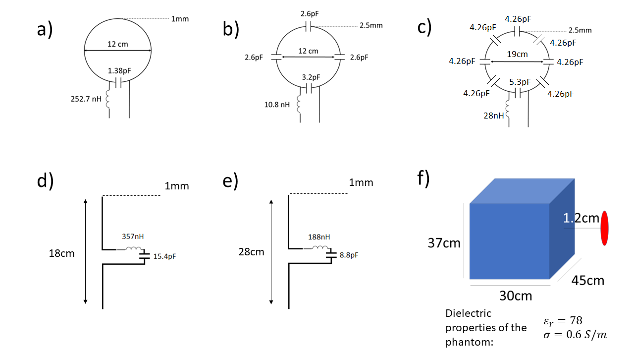
Using simulations (CST Studio Suite 2023), we analysed surface current distribution, SAR efficiency, SNR, coupling, and flexibility, i.e. shape robustness- of a loop coil. Simulations were complemented with on-bench measurements using a VNA (Agilent Fieldfox) to validate the predicted coupling and flexibility performance.We used round and elliptic shapes, with two different coil orientations, i.e. port orthogonal to/parallel to B0. Coils were simulated at 1.2cm distance from a square phantom (Figure 1f). A circuit co-simulator was used for tuning and matching. First, a 12cm diameter loop (Figure 1a) was variously elongated with constant perimeter (100mmx140mm, 86mmx150mm, 62mmx168mm, 42mmx180mm). SAR efficiency was compared to efficiencies of a 12cm conventional loop (Figure1b) and a 18cm dipole (Figure1d). Then, elongation optimization was performed to provide a boost at depth over a conventional coil, or a dipole alone. For elongation optimization, the electrical length of the loop was changed with a constant axial coverage (62mmx200mm, 62mmx240mm, 62mmx280mm), and a 19cm diameter conventional loop (Figure 1c) and 28cm dipole (Figure 1e) were used for comparison.
For flexibility, we report S11 of round and elongated elements. SAR efficiency was $$$B_1^+/\surd{maxSAR_{10g}}$$$. For SNR, $$$SNR=B_1^-/\surd{4kTRe\{Z11\}\Delta f}$$$5,6. The ratio between the power dissipated in the load and in the coil metal was used equivalently to the ratio between sample and coil resistance. For array simulations, eight 62mmx280mm coils were uniformly distributed at 1.2cm distance from a 30cm diameter cylindrical phantom. A CP+ mode was excited, and transmit efficiency and coupling were compared to an array of 12cm conventional loops, and 28cm dipoles.
Results
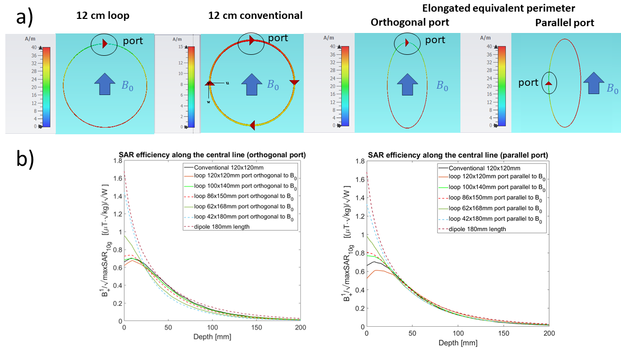
Figure 2a shows the surface current of different designs. Loops, and elongated loops, had higher current opposite to the feeding point (High-Current-Arm/HCA), and lower current at the feeding point (Low-Current-Arm/LCA).Figure 2b compares SAR efficiency along the central line of different designs. When elongations were performed with port orthogonal to B0, gain at the surface was compensated with losses at depth >2cm. Performing elongations with the port parallel to B0 allowed similar surface gain, with better or comparable SAR efficiency than a conventional loop at depth >2cm.
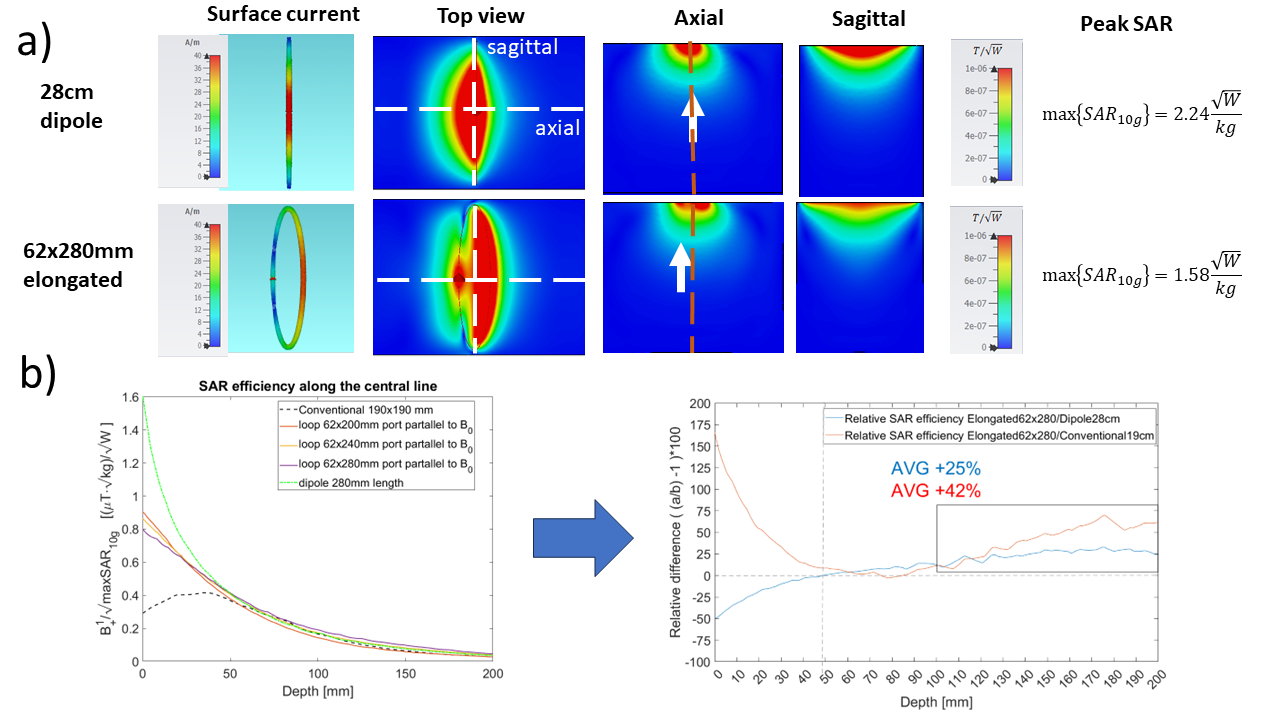
Figure 3 shows the results of elongation optimization process. Due to similar transmit efficiency to a dipole, with less SAR (Figure 3a), the 62mmx280mm design provided +42% average SAR efficiency than a conventional loop, and +25% average SAR efficiency than a dipole in the range [10,20]cm depth (Figure 3b).
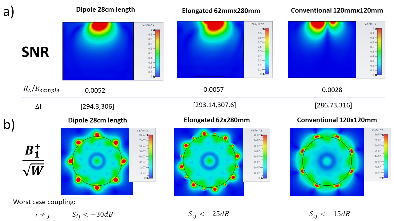
Figure 4 shows the results for SNR of single elements, and transmit efficiency in array configurations, of the optimized design(62mmx280mm). Both transmit efficiency and SNR were very similar to a dipole, and noise body dominance was achieved.
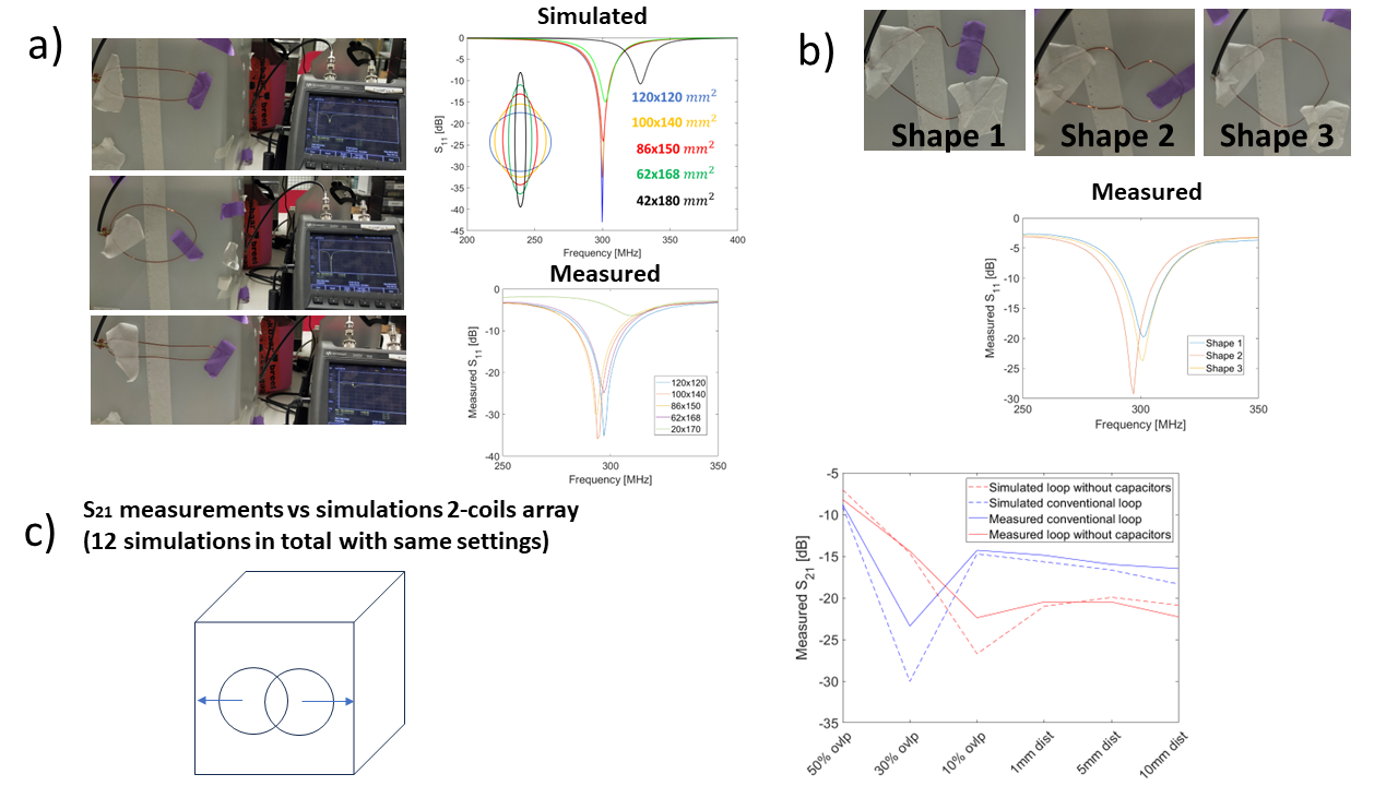
Figure 5 compares on-bench measurements and simulations of flexibility, and coupling between two elements.
Discussion
Currents on a loop could be regarded as the superposition of loop and dipole surface currents. Orienting the port parallel to the direction of the main magnetic field proved more important than elongation to improve efficiency at depth. This orientation –so far unexplored [3][4]- brings the dominant(dipole-like) contributions of the magnetric field in the transverse plane, thus maximizing B1+/-. The elongation optimization strategy - performed with the aim of stretching currents in the HCA to better approximate a dipole – proved effective, with the optimized 62mmx280mm design providing a SAR efficiency boost over a conventional loop, or a dipole alone, with similar SNR and transmit efficiency of dipoles. No detuning occurred when coils were bended over a cylinder, and in the presence of other coils. Flexibility-i.e. S11<-10dB when coil was conformed to different shapes and/or elongated or deformed- enables seamless implementation of the investigated designs.Conclusions
An elongated design of loops provided higher performance than conventional loops and dipoles in terms of SAR efficiency at depth, with flexibility, and low coupling. Results in this work provide a new avenue to explore in flexible coil design.Acknowledgements
No acknowledgement found.References
[1] Lakshmanan, K. et al, The “Loopole” Antenna: A Hybrid Coil Combining Loop and Electric Dipole Properties for Ultra-High-Field MRI , Concepts in Magnetic Resonance Part B, Magnetic Resonance Engineering, 2020, DOI: 10.1155/2020/8886543
[2] Hernandez D. et al. Study on the Effect of Non-Symmetrical Current Distribution Controlled by Capacitor Placement in Radio-Frequency Coils for 7T MRI. Biosensors 2022, 12, 867, DOI: https://doi.org/10.3390/bios12100867
[3] Güler S. et al. Shielded-coaxial-cable (SCC) coils - the array configuration for maximized central SNR at 7T MRI , in Proc. Intl. Soc. Mag. Reson. Med, 2022, Link: https://archive.ismrm.org/2022/1538.html
[4] Ming Lu et al Over-overlapped loop arrays: A numerical study Magnetic Resonance Imaging, Vol, 72, 2020, pp. 135-142 DOI: https://doi.org/10.1016/j.mri.2020.07.006
[5] Roemer, P. B., et al. The NMR phased array, in Magnetic resonance in medicine 16.2 (1990): 192-225
[6] Hoult D.I. The NMR receiver: A description and analysis of design, in Progress in Nuclear Magnetic Resonance Spectroscopy Volume 12, Issue 1, 1978, Pages 41-77
Figures