1430
Solenoid Float Cable Trap for MRI1College of Nuclear Equipment and Nuclear Engineering, Yantai University, Yantai, China, 2Department of Electrical and Computer Engineering, Vanderbilt University, Nashville, TN, United States, 3Vanderbilt University Institute of Imaging Science, Vanderbilt University Medical Center, Nashville, TN, United States, 4Department of Radiology and Radiological Sciences, Vanderbilt University Medical Center, Nashville, TN, United States
Synopsis
Keywords: RF Arrays & Systems, New Devices
Motivation: Float cable trap has gained widespread adoption in RF coil owing to its unique advantages. However, conventional float trap requires considerable dimensions to achieve an excellent performance.
Goal(s): This study is aiming to propose a novel float balun that can achieves high performance but with a compact size.
Approach: It was inspired by the well-established solenoid trap. The solenoid structure leverages strong inductive coupling between the cable shield and float resonator, ensuring high efficiency and enabling a compact design.
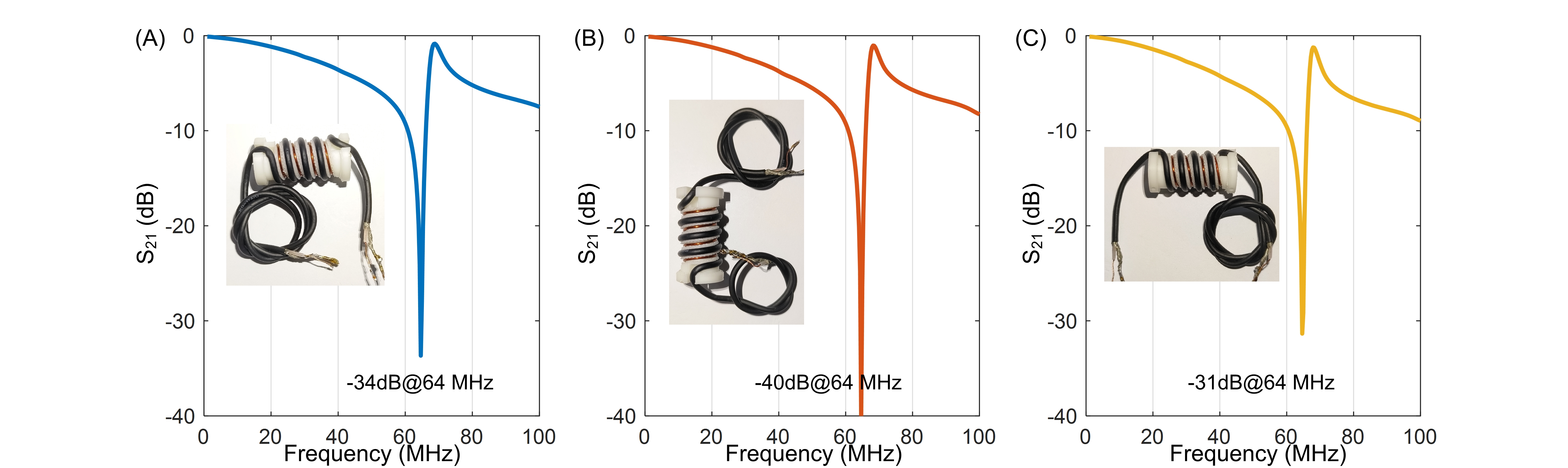
Results: With a compact size of 1.5x3cm2, solenoid float balun shows a measured CMRR of -31 dB (vs. -5 dB using conventional float trap).
Impact: The novel, compact and float balun offers significant advantages in the field of MRI RF coil and RF safety. It reduces the overall bulkiness of the RF coil, enables the incorporation of a greater number of elements in receive arrays.
INTRODUCTION
Cable traps are essential components in RF coils that suppress common-mode currents along the cable shield [1, 2]. The float cable trap [3] has gained widespread adoption in MRI. This unique floating design allows for easily adjusting the float balun's position, enabling effective common-mode current minimization. Another significant advantage is that it eliminates the need for soldering on the cable shield, thereby reducing the risk of introducing failure modes to the cable.The conventional float trap is based on the Bazooka balun, requiring considerable dimensions to achieve an excellent common-mode rejection ratio (CMRR) [3]. For instance, the original float balun has an outer diameter of approximately 2.5 cm and a length of about 8 cm for 1.5 T MRI [3]. Modern MRI scanners with denser coil arrays have a growing demand for more compact cable traps. This study proposes a novel float trap inspired by the well-established solenoid trap [4]. The solenoid structure leverages strong inductive coupling between the cable shield and float resonator, ensuring high efficiency and enabling a compact design.
METHODS
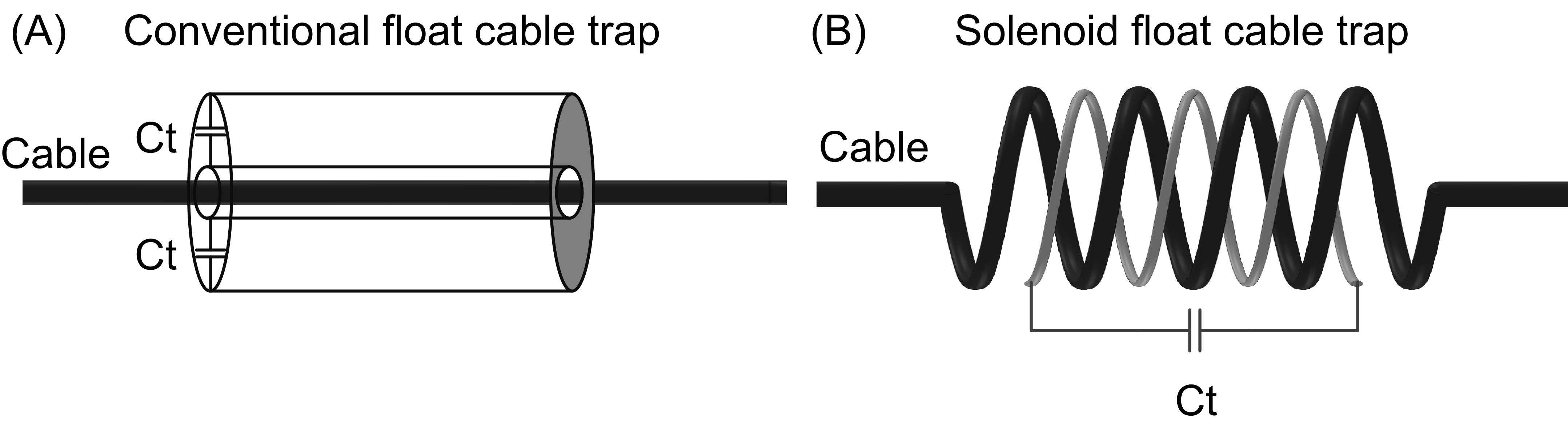
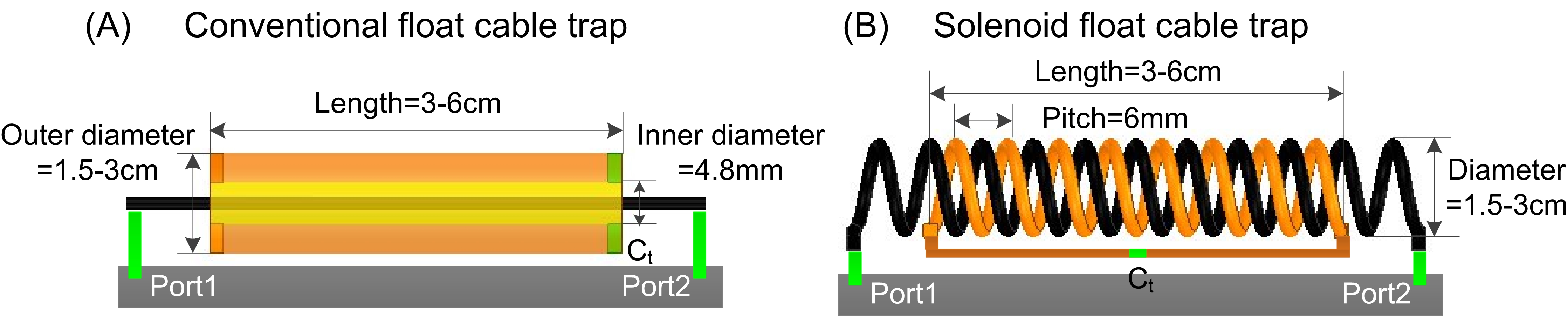
Figure 1 depicts circuit diagrams of the conventional and solenoid float cable traps. An additional solenoid resonator was employed to inductively couple with the cable shield, effectively trapping unwanted RF signals at the desired frequency.We compared the CMRR performance of the conventional and proposed float traps through EM simulation (Figure 2). The trap's diameter (Dtrap) varies from 1.5 cm to 3.0 cm in 0.5 cm increments, while the trap's length varies from 3 cm to 6 cm in 1 cm increments. The pitch between the cable shield and the wire of the add-on solenoid resonator is maintained at a constant value of 3 mm. The number of turns in the solenoids varies (from 4 turns to 10 turns) to achieve different Ltrap values in the solenoid float trap. CMRR was evaluated as the S21 between the two ports connected through a large ground plane. Terminated capacitors were adjusted to ensure that all cable traps were tuned to 64 MHz, the Larmor frequency of 1.5 T.
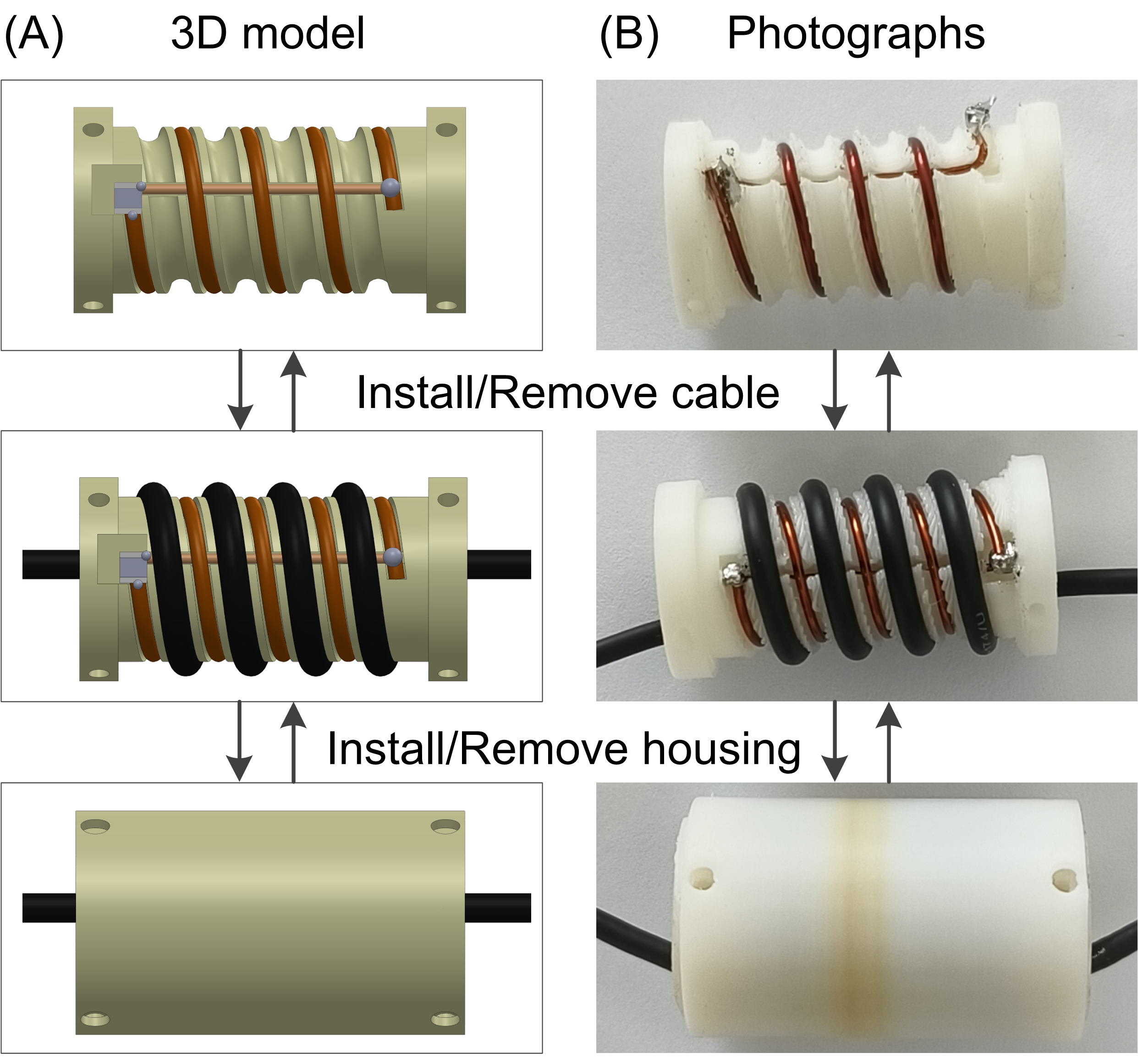
Figure 3A and 3B display the CAD models and photographs of the fabricated solenoid cable trap. A solenoid float trap with Dtrap/Ltrap of 1.5/3 cm was manufactured for 1.5 T. Due to the absence of physical connections with the cable shield, one can adjust the trap's position along the cable by disassembling and reassembling it. The housing for the float cable trap was meticulously designed using Solidworks and manufactured with a 3D printer, ensuring precise and replicable assembly. Within the housing, slots were incorporated to securely and snugly accommodate the solenoid cable.
RESULTS
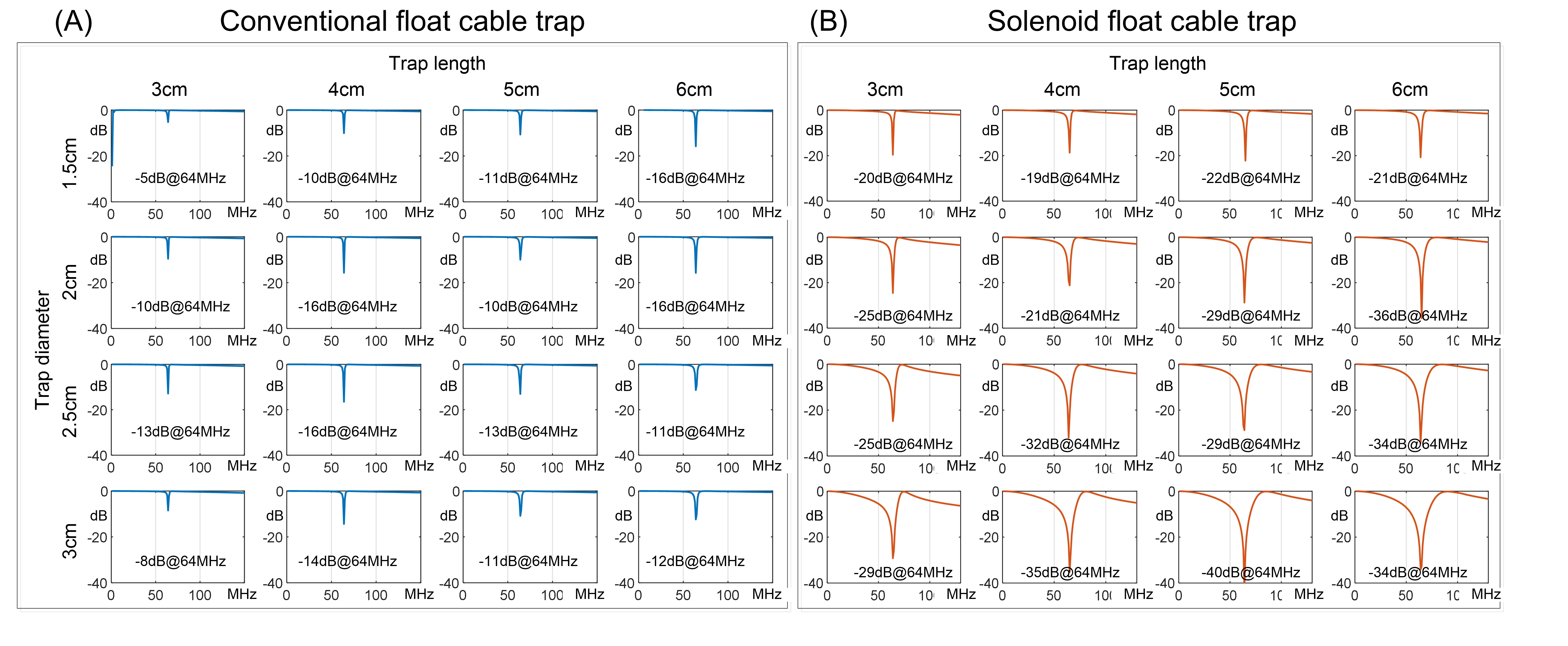
Figure 4 compares the simulated CMRR of 1.5T traps with different dimensions. The simulated CMRR of the conventional trap is -12 dB with a Dtrap/Ltrap of 3/6 cm. For a compact design with Dtrap/Ltrap of 1.5/3 cm, the CMRR worsens to only -5 dB. In contrast, using the solenoid design, the same-sized compact float trap maintains an excellent CMRR of -20 dB. CMRR represents the attenuation of the common-mode signal. -3 dB means there is still approximately 50% residual common-mode signal, while -20 dB means only 1% remains. Additionally, the solenoid float trap has a larger bandwidth, providing a higher tolerance for the capacitors and simplifying the practical fabrication process.Figure 5 displays the bench test results of the fabricated cable trap for 1.5 T MRI. Consistent with the simulation results, the measured CMRR of solenoid float traps achieve <-31 dB at 64 MHz, much better than a conventional float balun (~-5 dB with same dimension). We observed no frequency shift by changing the balun’s position along the cable. This confirms that, even after disassembly and reassembly of the trap, the cable length within the solenoid remains unchanged, maintaining the trap's operating frequency.
CONCLUSION
We introduced a novel float cable trap based on the well-established solenoid trap. This design retains the advantages of a conventional float trap, such as being removable and not requiring a physical connection to the cable. However, it also overcomes the low CMRR limitation of conventional float traps and can be manufactured in a compact size while maintaining excellent CMRR performance.Acknowledgements
This work was in part supported by NIH grants R03 EB034366 and R01 EB031078. The content is solely the responsibility of the authors and does not necessarily represent the official views of the National Institutes of Health. This work was performed during the period of Dr. Ming Lu’s visit to Vanderbilt University Institute of Imaging Science.References
- D. M. Peterson, B. L. Beck, G. R. Duensing, and J. R. Fitzsimmons, “Common mode signal rejection methods for MRI: Reduction of cable shield currents for high static magnetic field systems,” Concepts in Magnetic Resonance Part B: Magnetic Resonance Engineering, vol. 19B, no. 1, pp. 1–8, 2003, doi: 10.1002/cmr.b.10090.
- X. Yang, T. Zheng, and H. Fujita, “Baluns , and Detuning Elements in MRI RF coils,” 2006. Accessed: Oct. 27, 2023. [Online]. Available: https://www.semanticscholar.org/paper/Baluns-%2C-and-Detuning-Elements-in-MRI-RF-coils-Yang-Zheng/ff8c3c85962277d322b8eac243ce46b3b52cff63
- D. a. Seeber, J. Jevtic, and A. Menon, “Floating shield current suppression trap,” Concepts in Magnetic Resonance Part B: Magnetic Resonance Engineering, vol. 21B, no. 1, pp. 26–31, 2004, doi: 10.1002/cmr.b.20008.
- W. H. Harrison, M. Arakawa, and B. M. McCarten, “RF coil coupling for MRI with tuned RF rejection circuit using coax shield choke,” US4682125A, Jul. 21, 1987 Accessed: May 31, 2022. [Online]. Available: https://patents.google.com/patent/US4682125A/en.
Figures