1428
Testing platform for comparison between optical position tracking systems for motion correction1Medical Biophysics, University of Toronto, Toronto, ON, Canada, 2Sunnybrook Research Institute, Toronto, ON, Canada
Synopsis
Keywords: New Devices, Brain, Optical position tracking
Motivation: Optical position tracking (OPT) systems have been used successfully in motion correction, however, the comparison of new and pre-existing OPT systems remains challenging due to lengthy calibration procedures.
Goal(s): Our goal was to create a testing platform capable of operating two systems concurrently for validating new OPT methods.
Approach: Two dual camera systems were set up in the magnet room with a custom calibration stage. A phantom was used to transform coordinates from the camera to the magnet coordinate frame.
Results: Camera calibration is limited to 30-minutes and outputs expected values. The pre-existing OPT system is accurate.
Impact: With this testing platform, two optical position tracking (OPT) systems can be compared simultaneously on participants in the MR environment, rather than individually on the benchtop. This allows validation of OPT methods that are highly dependent on the testing environment.
Introduction
Stereo-camera optical position tracking (OPT) systems have been used successfully in magnetic resonance imaging (MRI) for tracking six degree of freedom (DOF) rigid body head motion over time, enabling motion correction1. Such systems have excellent precision and temporal resolution, but setup and calibration time can be lengthy (possibly hours2), limiting clinical utility. Alternatively, a well-characterized, pre-existing OPT system can be used to validate a prototype tracking system that is potentially more robust – providing direct comparison with ground-truth tracking data in the MR environment as an important step toward validating the prototype. Here we describe the development and application of such an optimized platform for testing and validation.Methods
The pre-existing OPT system comprises two wall-mounted video-cameras at the rear of a 3 T Siemens Biograph mMR magnet room, angled to view the centre of the magnet bore, enabling tracking of a benchtop-validated custom fiducial marker rigidly attached to participants via a wearable device3 (Figure 1). Two calibrations are required: one to calculate the camera intrinsic and extrinsic parameters, which are used to undistort the images and to enable stereo tracking; and the second to calculate the transformation matrix from the camera coordinate frame to the magnet coordinate frame1,4. Both calibrations must be done with the cameras focused where the fiducial marker will be positioned5. The second prototype OPT system is also shown, comprising two in-bore, MRI-compatible video-cameras mounted around the head coil. The prototype will use simple camera focusing and artificial intelligence methods to translate video images into position tracking data, although accuracy and robustness remain to be verified.The first calibration (camera parameters) was optimized to minimize the number of calibration images and acquisition time while achieving acceptable results. The calibration images were required to span the entire range of the camera field of view and cover a variety of different angles to ensure a unique solution to the series of calibration equations4. The camera frame was divided into a 3x3 grid, and a calibration board was sequentially positioned at each grid location in five different orientations (forward facing, tilting left, right, up, and down). These placements were undertaken repeatably using an MR-safe calibration stage (Figure 2). The calibration stage was placed on the patient table near the head coil and moved to the centre of the bore where the cameras were focused for image capture. The image data were then imported into a Python script that generated the intrinsic and extrinsic camera parameters.
The second calibration (coordinate transformation) used a custom-made phantom with 15 jointly camera- and MRI-visible points that were then used to calculate the transformation matrix from OPT system coordinates to MRI system coordinates via singular value decomposition7 (Figure 3).
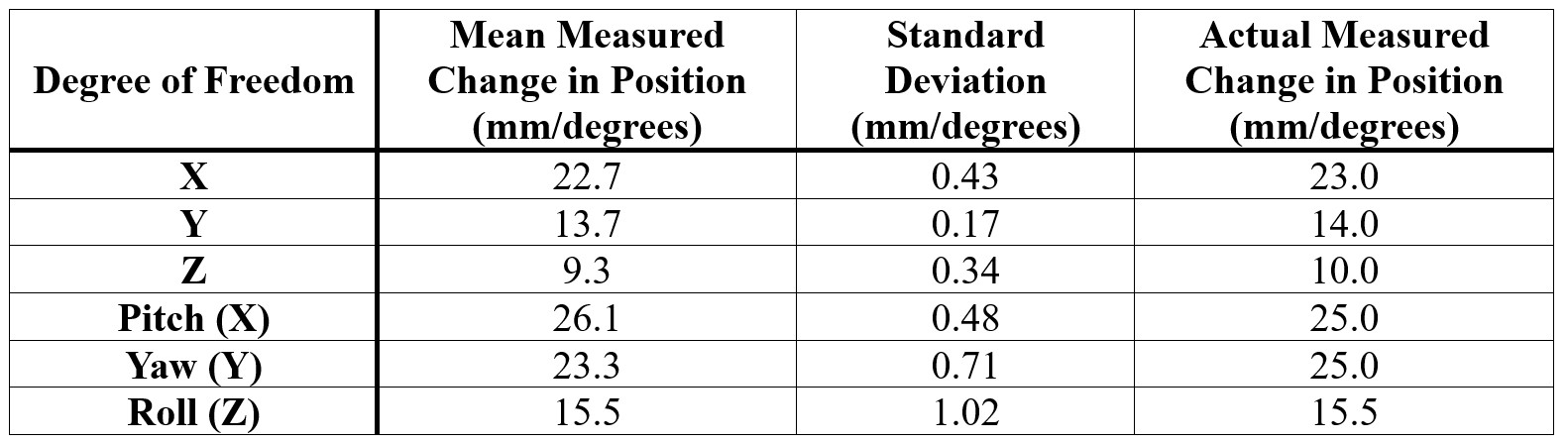
Lastly, the ground truth fiducial marker was tested for accuracy by placing it on the calibration stage and moving it to various known locations – including use of a second horizontal slot positioned 1 cm further along the Z axis to confirm translational shifts in that dimension.
Results
Calibration data are summarized in Table 1, listing only the extrinsic camera parameters for brevity as they depend on the accuracy of the intrinsic parameters. The fiducial marker validation results indicate accurate performance in the MR environment (Table 2).Discussion
Regarding calibration, the video-cameras were separated approximately 60 cm from each other, whereas the extrinsic parameters accurately estimated the separation at 603 mm. The camera and MRI coordinate frames were known to have opposed positive conventions for the X and Z axes, and the transformation matrix accurately showed approximately 180° rotations about X and Z.The in-bore results of the fiducial marker showed good agreement between expected and actual measurements. Some of the inaccuracy in the measurements is likely due to construction of the stage, which did not have millimeter precision, but the overall results support the accuracy of the fiducial measured at the benchtop3.
These results suggest that the ground truth OPT system is ready to be used as a point of comparison to test prototype PT devices with improved robustness and practicality. The calibration time is reasonable (~30 minutes). This testing platform could be easily replicated on other MRI systems for use in diverse PT applications.
Conclusion
A testing platform has been optimized to validate prototype PT devices against a pre-existing, accurate OPT method. Next steps will include using this setup to validate a new OPT system in development in the lab.Acknowledgements
No acknowledgement found.References
1. Godenschweger, F. et al. Motion correction in MRI of the brain. Phys Med Biol 61, R32–R56 (2016).
2. Maclaren, J. et al. Measurement and Correction of Microscopic Head Motion during Magnetic Resonance Imaging of the Brain. PLoS ONE 7, (2012).
3. Silic, M., Jegatheesan, A., Tam, F. & Graham, S. J. Optical position tracking fiducial marker for rigid body motion parameter estimation with high performance. Proceedings of the International Society for Magnetic Resonance in Medicine, Scientific Meeting and Exhibition (2023).
4. Zhang, Y.-J. Camera Calibration. in 3-D Computer Vision: Principles, Algorithms and Applications (ed. Zhang, Y.-J.) 37–65 (Springer Nature, 2023). doi:10.1007/978-981-19-7580-6_2.
5. Bradski, G. The OpenCV library. Dr. Dobb’s Journal 25, 120–125 (2000).
6. Dai, H., Pears, N., Smith, W. & Duncan, C. Statistical Modeling of Craniofacial Shape and Texture. Int J Comput Vis 128, 547–571 (2020).
7. Umeyama, S. Least-squares estimation of transformation parameters between two point patterns. IEEE Transactions on Pattern Analysis and Machine Intelligence 13, 376–380 (1991).
Figures
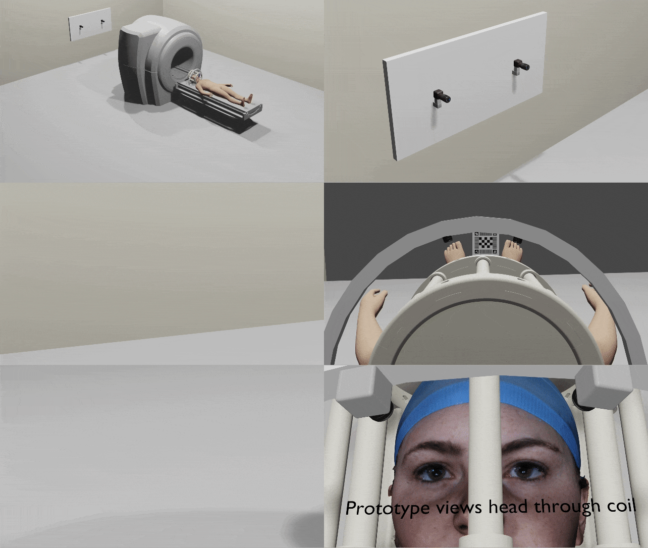
Figure 1. Animated model layout of the ground truth and prototype OPT systems as they are currently arranged. The head model is from the Headspace dataset6. Click the image to view the animation.
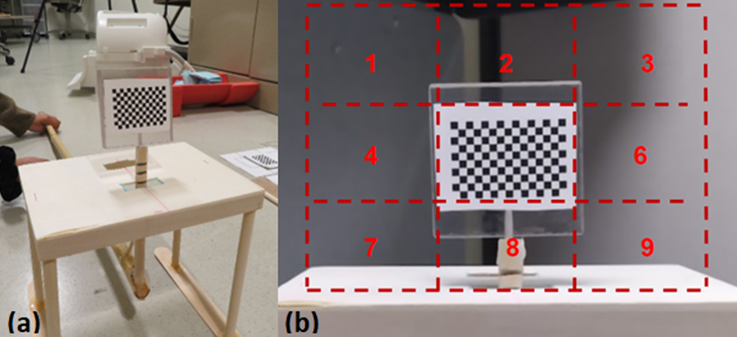
Figure 2. MR-safe calibration stage. (a) Stage shown with calibration board, a horizontal hole 3.2 cm long, paired with an adjustable post (0.9 cm diameter) with three vertical notches equally spaced 0.7 cm apart (1.4 cm total length). The notches rested in the front of the horizontal slot, allowing the user to move the calibration board to nine positions. The notches allowed in-place rotations to known limits. (b) Graphical depiction of nine positions for calibration, not to scale.
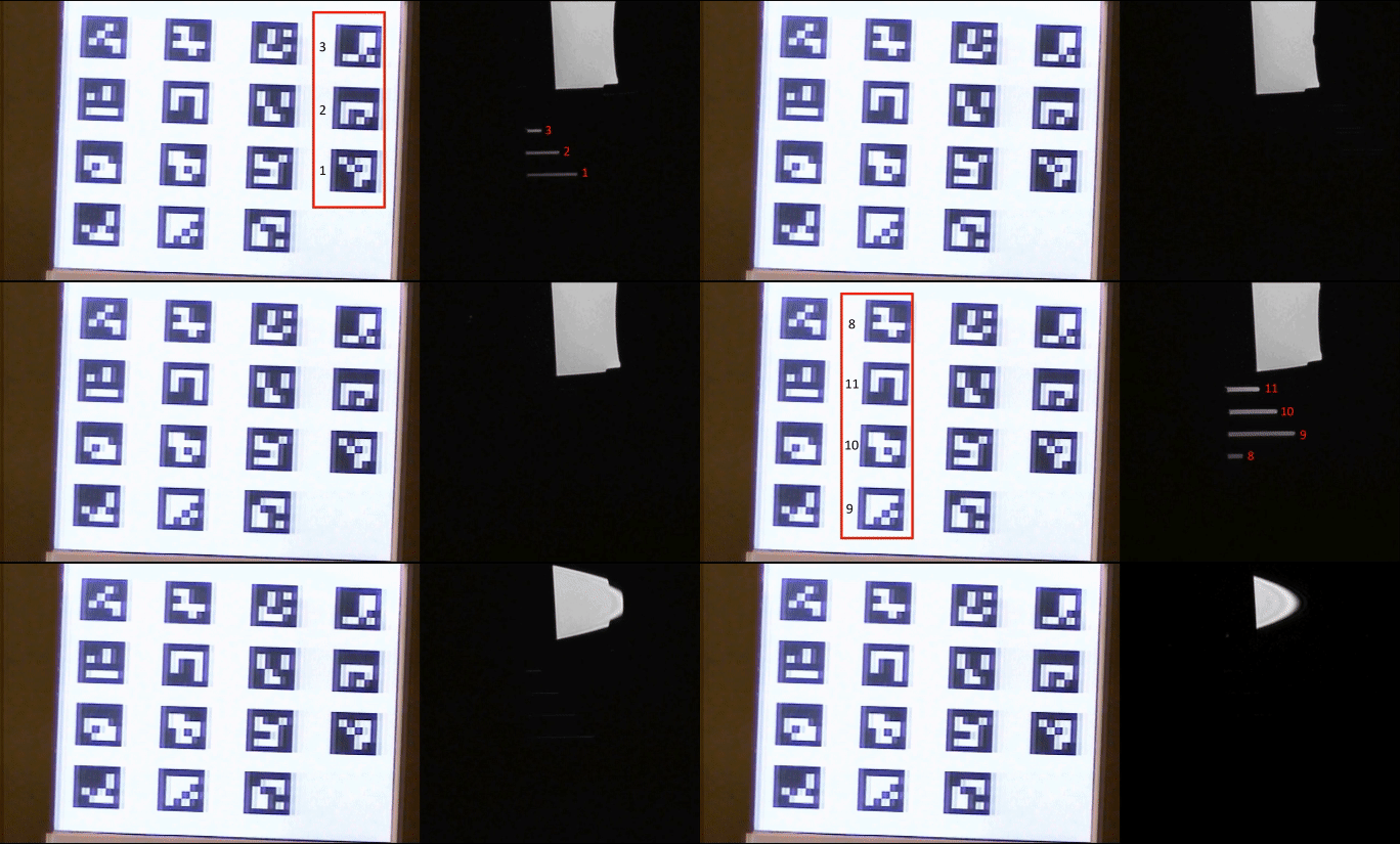
Figure 3. Camera- and MRI-visible points for the transformation matrix calculation. Left: Camera-visible ArUco points. Right: MRI-visible points taken from sagittal T1-weighted images. The signal at the top of the image is from a bottle phantom for coil loading. Click on the image for the animation showing labelled matched points. Sagittal slices are displayed from right to left.
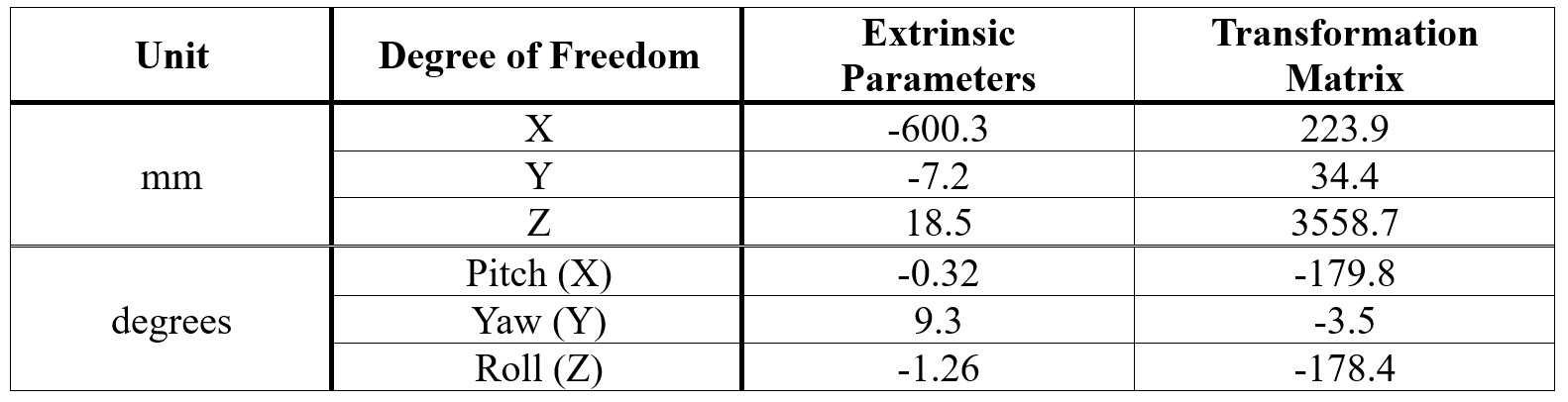
Table 1. Extrinsic Parameters and Transformation Matrix Results