1427
A system supervisor for safer parallel radiofrequency transmission MRI research1Physical Sciences, Sunnybrook Research Institute, Toronto, ON, Canada, 2Department of Medical Biophysics, University of Toronto, Toronto, ON, Canada
Synopsis
Keywords: Parallel Transmit & Multiband, RF Arrays & Systems, FPGA, RFPA
Motivation: Careful attention to safety is required for human research with novel parallel transmission (PTx) MRI technologies, particularly when they may cause harmful interactions with implanted devices.
Goal(s): Our goal was to add an additional layer of safety during experiments with a custom PTx research platform.
Approach: A system supervisor was created to monitor and react to a variety of amplifier faults and power conditions.
Results: Initial tests showed that it could safely disable the PTx system with acceptably short and stable response times.
Impact: A system supervisor was developed and tested for parallel transmission MRI research. The presence of such a supervisor may accelerate acceptance of PTx research systems by safety-conscious researchers and reviewers.
Introduction
Parallel transmission (PTx) applies radiofrequency (RF) power via multiple independent transmission channels, increasing the possible points of failure. Moreover, research PTx platforms typically include multiple nonstandard amplifiers and other hardware and software, which are not anticipated in the design of safety systems provided by clinical MRI vendors. Human research with novel PTx techniques demands careful attention to safety, particularly for research into safer imaging of patients with implants1. Simulation and phantom validation studies are vital to develop such techniques. Additional assurance may be afforded by the presence of an external (MRI vendor independent) system supervisor. A system supervisor for a custom PTx research platform was developed and tested in the present work.Methods
The PTx system supervisor was added to an existing 4-channel PTx research platform2 and an 8-channel enhancement under development3. The supervisor was implemented using National Instruments equipment (Figure 1): a PXI-express chassis (PXIe-1085) with embedded controller (PXIe-8135) and LabVIEW FPGA software (v2015), two multifunction data acquisition boards (PXI-7853R) with programmable FPGAs (field programmable gate arrays), and a 32-channel voltage input board (PXIe-4302) sufficient for up to 16 PTx channels.Figure 2 shows an overview of the supervisor structure, including the PTx System Supervisor software and the signal connections to the PTx platform. For high reliability and low latency, the FPGA processor was dedicated to crucial functions for gathering RF power amplifier (RFPA) status and power sensor data and then deciding whether an abnormal event requires shutdown, while the Controller managed the graphical user interface. Possible faults included RFPA errors (temperature, duty cycle, etc.) and reflected/forward power limits (single channel or combined). The main interface functionality was to disable the whole system immediately in response to a fault in one or more PTx channels, and to display and hold the fault until the Reset button was clicked.
Reflected and forward RF power levels were available from a pair of custom power sensors (described separately) per PTx RF channel, connected to the RFPAs (BT00500-AlphaSA-6751 or BT01000-AlphaSA, Tomco Technologies). RFPA status indicators were available from diagnostic ports, which also allowed disabling the RFPA via dedicated Enable inputs (for the 4-channel system) or by grounding the gating trigger lines (for the 8-channel system). Figure 3 shows a circuit used for disabling both RFPA types, and for disabling the custom trigger adaptor (described separately) used to synchronize the PTx system with the MRI system. Thus, by lowering the enable signal, by powering off the supervisor, or by pressing a redundant hardware stop button, the disable circuit inhibited key stages of the PTx system, from signal generation to amplification.
As part of bench testing to verify functionality, RFPA faults were simulated or induced, and the response time to disable the system was measured using an oscilloscope (TDS2022 or TDS2024, Tektronix).
Results
During bench testing, an average response time of 2.4 µs was logged, with minimum 1.2 µs and maximum 2.9 µs across nine tests (Figure 4). Functionality was as expected, but limitations are discussed below.Discussion
An external system supervisor was added to a PTx research platform, to provide an additional layer of assurance prior to experiments in humans. This was necessitated by the structure of such research platforms, which add nonstandard equipment to build multiple transmission chains outside the purview of the clinical MRI system’s protections. Despite this necessity, such systems are not usually seen in the PTx research literature, although the major MRI vendors have presumably extended the proprietary protections in their clinical PTx products. Reliance on simulation and limited validation studies may be adequate for PTx research in healthy humans, but the stakes are raised when patients with medical implants are imaged, or when equipment fails during an experiment.The present supervisor was designed and tested to respond to dozens of RFPA faults and RF power events, and was found to disable the system with low latency. Planned improvements include development and inclusion of models for SAR and tissue heating estimation, to address important regulatory limits. The existing reflected/forward power limits are already helpful in this regard, but they are less rigorous, suited more for protecting equipment than humans. SAR modelling can be co-developed in the lab during ongoing simulation and PTx pulse sequence research into SAR reduction, for safer imaging of patients with implants4.
Conclusion
A PTx system supervisor was developed and tested for PTx MRI research. It will be further improved and used as an additional layer of assurance for safer PTx experiments.Acknowledgements
Supported by Canada Foundation for Innovation and Canadian Institutes of Health Research.References
1. Eryaman Y, Guerin B, Akgu C, Herraiz JL, Martin A, Torrado-Carvajal A, Malpica N, Hernandez-Tamames JA, Schiavi E, Adalsteinsson E, Wald LL. (2015) Parallel Transmit Pulse Design for Patients with Deep Brain Stimulation Implants. Magn Reson Med. 2015; 73: 1896-1903.
2. Yang B, Wei PS, McElcheran CE, Tam F, Graham SJ. A platform for 4-channel parallel transmission at 3T: Demonstration of reduced radiofrequency heating in a test object containing an implanted wire. J Med Biol Eng. 2019; 39: 835.
3. Yang B, Tam F, Arianpouya M, Leone C, Li V, Rock J, Graham S. A Modular Parallel Radiofrequency Transmission System Platform for MRI Safety Investigations at 3 T. Proc Intl Soc Magn Reson Med. 2023; 33: 2869.
4. McElcheran CE, Yang B, Anderson KJT, Golestanirad L, Graham SJ. Investigation of Parallel Radiorequency Transmission for the Reduction of Heating in Long Conductive Leads in 3 Tesla Magnetic Resonance Imaging. PLoS One. 2015; 10(8): e0134379.
Figures
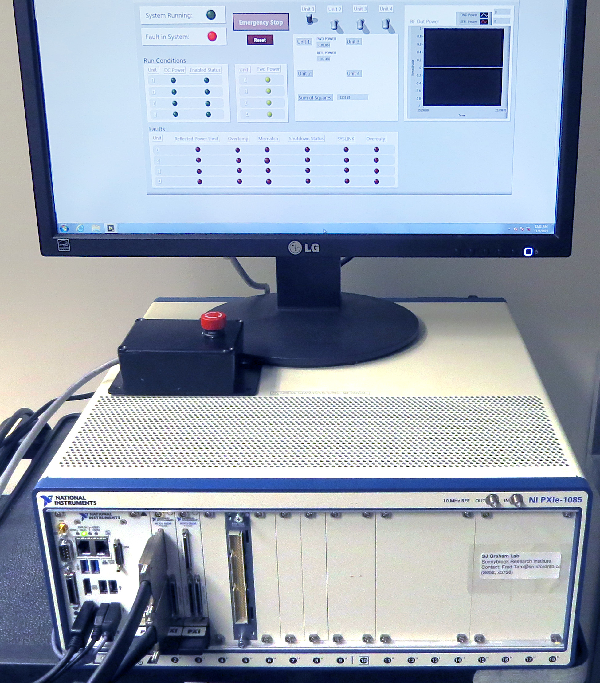
Figure 1. The PTx System Supervisor hardware, including the circuit for manually enabling/disabling the PTx system (box with the red stop button). The graphical interface for 4-channel PTx is shown.
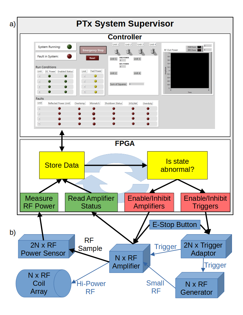
Figure 2. An overview of the system supervisor’s structure. a) The top section represents the Supervisor software, which is implemented in separate processes on the controller (for the graphical interface) and on the FPGA (for reliably gathering data and making the decision whether to disable the system). b) The bottom section shows signalling flows between major components of the PTx platform, where bold black arrows indicate new connections for the supervisor.
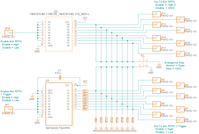
Figure 3. The prototype circuit for disabling the PTx system when the supervisor’s enable signal drops, whether in response to an abnormal event or if the supervisor’s power fails. The top half maintains high impedance while enabled, and grounds all outputs to disable the RFPAs for 8-channel PTx. The bottom half pulls all outputs high while enabled, and pulls all outputs low to disable the trigger adapter and the RFPAs for 4-channel PTx. A mechanical stop button grounds all outputs if pressed.
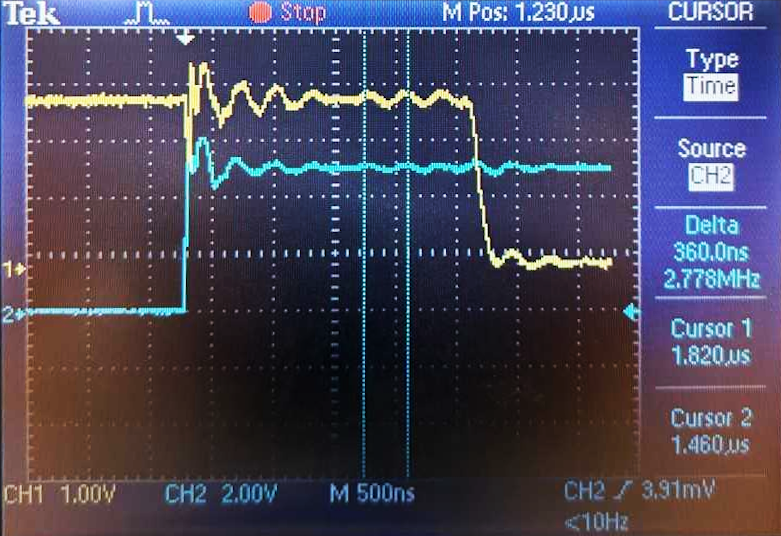
Figure 4. A representative oscilloscope screenshot showing the supervisor’s response to a fault condition, a simulated RFPA error in this case. Channel 2 (blue) plots the error being raised, and Channel 1 (yellow) plots the RFPA enable line being lowered in response. The average delay was 2.4 µs. (Some slight crosstalk was visible between lines in this example, much of which was due to the DAQ itself, but it has been reduced to an acceptable level.)