1426
A fully autonomous system for sequence detection and gradient measurement1ETH Zurich, Zurich, Switzerland
Synopsis
Keywords: Hybrid & Novel Systems Technology, Hybrid & Novel Systems Technology
Motivation: The threshold to efficient use of field cameras is high and they could benefit from being less dependent on the scanner system they're being used in.
Goal(s): The aim of this work is to develop an independent field monitoring system that can synchronize itself with and make targeted measurements of MR sequences.
Approach: We employ a commercial NMR field probe system and trigger it externally using a host PC for data processing and an FPGA as a timing system.
Results: We are able to independently synchronize the monitoring system, make targeted measurements of a sequence and decompose a set of gradient waveforms.
Impact: This work is a step towards enabling scanner independent monitoring of MR sequences with NMR field probes. This could be useful in cases where the integration of a field camera is not an option.
Introduction
NMR field cameras are powerful tools for monitoring and developing MR sequences[1]. Field probes can even be positioned individually to monitor actual imaging in any given setup[2]. Either of these however depend on position calibration which limits their use to sites with special access rights to their scanner systems. Further, NMR probes used in field cameras are prone to dephasing which typically prevents e.g. coverage of the full TR.The goal of the present work is to overcome these limitations. We demonstrate a fully scanner-independent system that uses NMR field probes to detect sequence periodicity, synchronize with the sequence, and perform a pseudo-continuous measurement of the entire TR. Making basic assumptions about sequence properties, the system can further infer the absolute probe positions and the gradient waveforms.
Methods
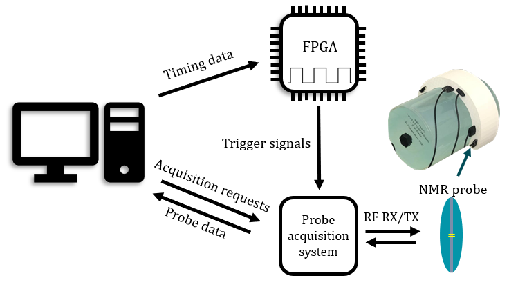
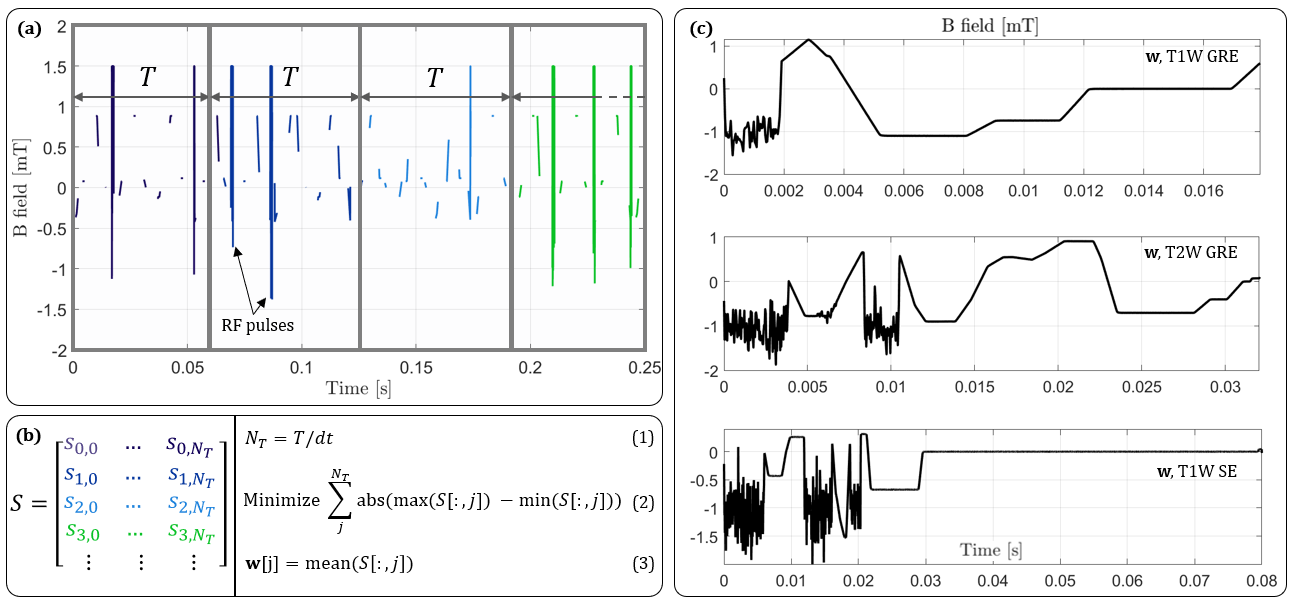
To acquire NMR probe data, we use a Skope acquisition system installed in a Philips Achieva 3T scanner. To prevent unwanted signal dephasing we deliberately use a set of short-lived probes with a T2 of about 2 ms and typically acquire signals in 1 ms snippets. The probes are positioned in pairs with known distances to help give a sense of scale. A host computer is responsible for data processing and an FPGA is used for timing. Fig. 1 illustrates the hardware setup.To monitor a sequence, the system and the scanner need to be synchronized in time. Typically, this is done through a physical timing link between field camera and scanner. For the sake of removing scanner dependence for this task, this system instead synchronizes itself with the scanner algorithmically. To do this, it initially acquires a larger set of short, randomly timed snippets over a few seconds. The detailed workings of the periodicity detection and synchronization are illustrated in Fig. 2.
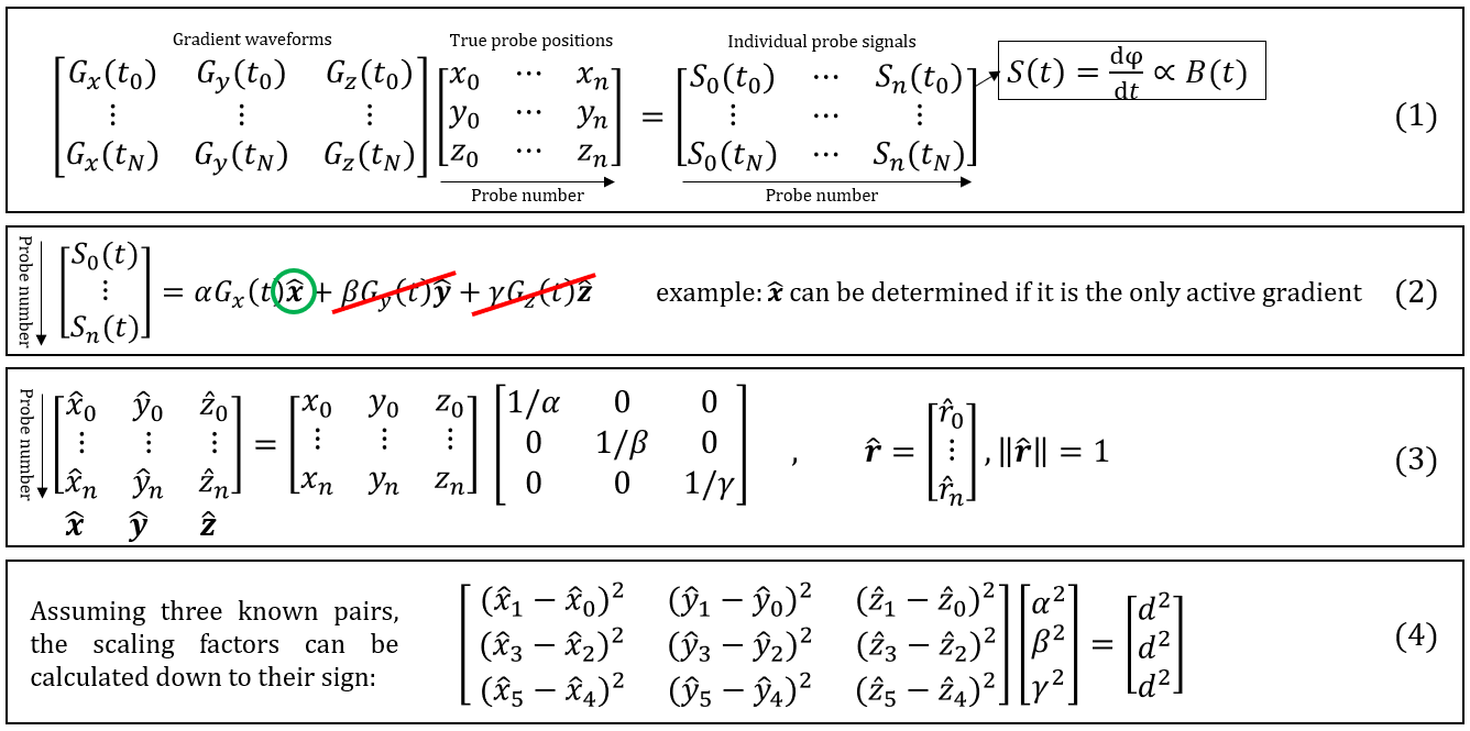
Once the periodicity of the sequence has been determined, a waveform w that is averaged over all acquired snippets can be calculated. This waveform serves as a pseudo-continuous observation of the sequence and can also be used for the system synchronization: In this waveform, a reference time point is chosen and a corresponding synchronization delay is calculated and communicated to the FPGA which executes the delay and from then on counts repeatedly to the periodicity T. Once synchronized, w can also be used for making targeted measurements: To showcase this, we make a few informed assumptions about the sequence: Assuming that there are a few moments in time where each gradient axis can be isolated, we can infer on the exact probe positions by using a set of probes with known relative positions. This is elaborated in Fig. 3. The system is able to single these instances out automatically, but relies on knowing what kind of sequence is running to correctly identify the different gradient events (e.g. slice selection).
Results
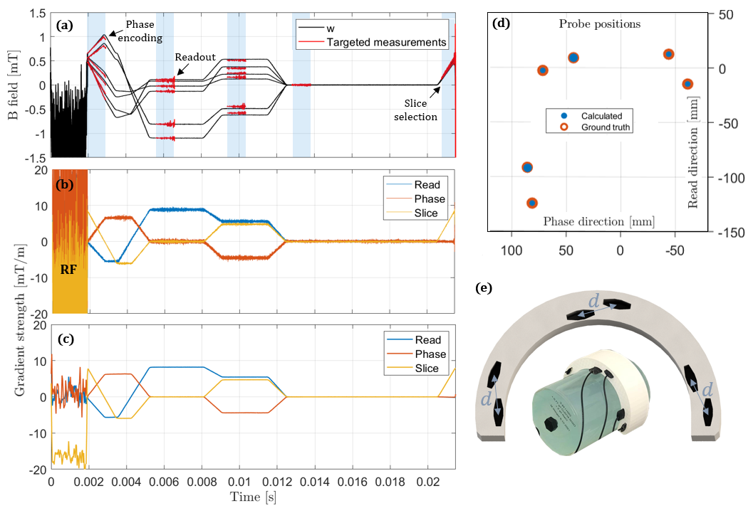
An illustration of successful periodicity detection can be found in Fig. 2 (c), where we show a set of averaged waveforms w for a few different sequence types with different periodicities. The time elapsed to reach this level of information is typically in the order of a sew seconds. In Fig. 4 (a), we demonstrate the possibility of making targeted measurements of the sequence based on w. Using these targeted measurements as inputs to our theoretical model, we are able to decompose the probe measurements to a set of gradient waveforms and absolute probe positions in the imaging coordinate system, Fig 4 (b-d).Discussion and outlook
In this abstract we demonstrate a stand-alone sequence monitoring device that independently synchronizes itself with a running sequence and that has the ability to self calibrate with some prior knowledge of the sequence. The system offers the possibility of making pseudo-continuous sequence measurements and can target gradient features without scanner integration, which has potential to lower the threshold to efficient use of field probes.Making assumptions about the sequence that is being monitored remains a disadvantage and there may be alternative ways of inferring absolute gradient waveforms and probe positions, such as treating it as an optimization problem or using machine learning. The current system can further not handle inaccuracies in the periodicity estimate, which makes it prone to timing drifts: this could be solved by implementing a resynchronization feature.
Acknowledgements
No acknowledgement found.References
[1]: Dietrich, Benjamin E., et al. "A field camera for MR sequence monitoring and system analysis." Magnetic resonance in medicine 75.4 (2016): 1831-1840
[2]: Vannesjo, S. Johanna, et al. "Retrospective correction of physiological field fluctuations in high‐field brain MRI using concurrent field monitoring." Magnetic resonance in medicine 73.5 (2015): 1833-1843.
Figures