1421
Reproducible and Miniaturized Bazooka RF Balun Using Printed Capacitor1Vanderbilt University Institute of Imaging Science, Vanderbilt University Medical Center, Nashville, TN, United States, 2College of Nuclear Equipment and Nuclear Engineering, Yantai University, Yantai, China, 3Department of Electrical and Computer Engineering, Vanderbilt University, Nashville, TN, United States, 4Department of Radiology and Radiological Sciences, Vanderbilt University Medical Center, Nashville, TN, United States
Synopsis
Keywords: New Devices, New Devices
Motivation: The balun or cable trap circuits associated with the RF coil are favored to be miniaturized, light-weighting, and even flexible.
Goal(s): We proposed a reproducible and miniaturized Bazooka balun using printed coaxial capacitors.
Approach: EM simulations were performed to guide the practical fabrication. The miniaturized Bazooka balun is made of the double-layer printed circuit board, allowing mass manufacturing ability in practice.
Results: The extremely thin layer in the printed capacitor (25 micrometers) provides a large capacitance of tens of pF per centimeter and allows the total length to be much shorter.
Impact: This reproducible and miniaturized balun is ideal for flexible and wearable RF coil designs, enhancing patient comfort and MRI image quality in diagnosis.
INTRODUCTION
RF coils with high density, lightweight, and high flexibility are desirable in modern MRI [1-7]. The balun or cable trap circuits associated with the RF coil are favored to be miniaturized, light-weighting, and even flexible. Bazooka balun [8,9] has been widely used in RF coils to suppress the common-mode signal running along the coaxial cable' shield. Chai et al. [10] demonstrated that the Bazooka balun could be miniaturized and flexible by replacing the shield conductor, lumped capacitors, and housing with a coaxial capacitor made of braids and heat shrink. However, the manual fabrication of the coaxial capacitor is still laborious, limiting the mass manufacturing ability. Meanwhile, the thickness of the heat shrink tube to form a dielectric layer for the coaxial capacitor is hundreds of micrometers. It limits the equivalent coaxial capacitance to only several pF per centimeter and requires a relatively longer length for the balun. For example, in the original design, the required balun length is approximately 5 cm/12 cm/30 cm at 7/3/1.5 Tesla. We proposed a miniaturized Bazooka balun using printed coaxial capacitors in this work. The coaxial capacitor was made of a flexible printed circuit board (PCB) to be easily reproduced in practice. The dielectric layer is as thin as 25 micrometers, so the length of baluns could be well reduced.METHODS
Figure 1A illustrates the structure of the Bazooka balun made of coaxial capacitors. In previous work, the coaxial capacitor was built manually using two copper braids and a heat-shrink tube between them (Figure 1B). In this work, the coaxial capacitor was made of a double-layer flexible PCB (Figure 1C). EM simulations were performed with Ansys HFSS to guide the practical fabrication. The total length of the balun (ltot, also the length of the inner conductor) varied from 6 cm to 16 cm for 1.5 T balun. The length of the outer conductor (i.e., the length of overlapping area) lout was carefully adjusted to ensure the operating frequency tuned to 64 MHz. For 3T and 7T where the required capacitor is smaller, the ltot varied from 2 cm to 10 cm, and from 1cm to 6 cm, respectively. The common-mode signal attenuation (CMSA) was evaluated as the transmission coefficient (S21) between two 50-ohm ports at the ends of the balun circuit and connected with a ground plane. Based on the simulation results, Bazooka baluns using the printed capacitor were fabricated and tested on the bench. Printed capacitors were made from double-layer flexible PCBs (manufacture info), with ltot of 8/4/2 cm and lout of 1.4/0.68/0.2 cm for 1.5/3/7 Tesla. The CMSA was measured on the workbench using a direct method [11,12].RESULTS and DISCUSSIONS
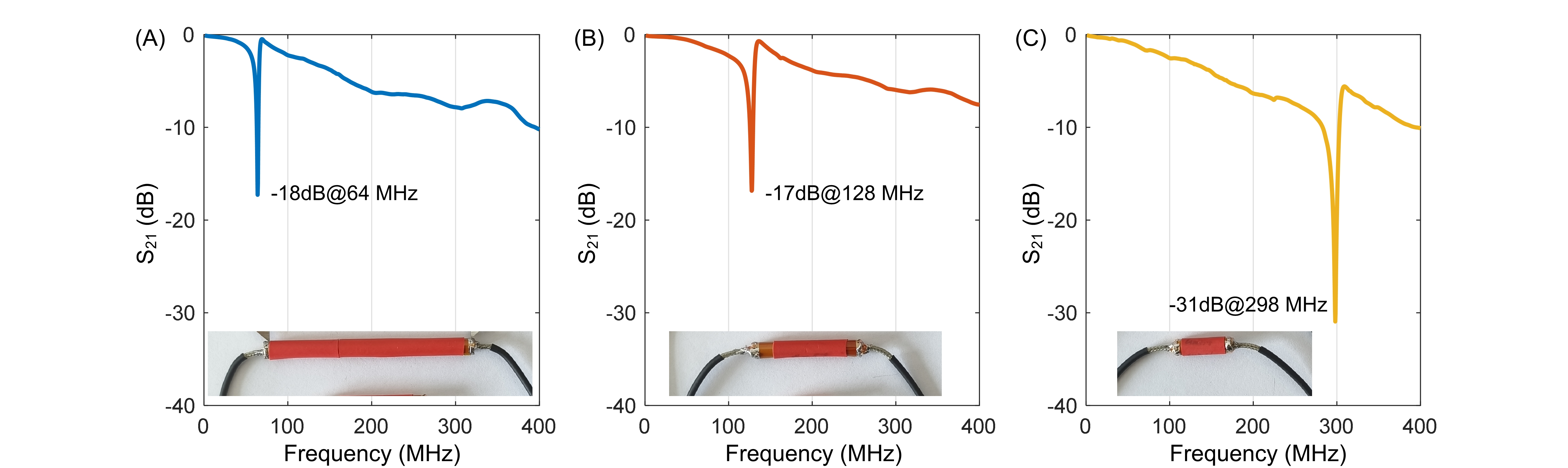
Figure 2 shows how CMSA changes concerning the ltot in the simulation. For each case, the dip of S21 plot was tuned to the desired frequency by adjusting lol. CMSA becomes better as the ltot increases. However, the CMSA becomes stable when the ltot reaches specific values (8cm/4cm/2/cm for 1.5/3/7 Tesla). These ltots were thereby selected in the practical balun fabrication. Figures 4 and 5 show the photographs and measured CMSAs of fabricated baluns on RG-174 cables. The measured CMSA is approximately -17 and -18 dB at 64 and 128 MHz. We noticed that the measured CMSA of a 2-cm-long 7T balun is better in practice (up to -31 dB). So, there is still room to reduce the ltot for 7T baluns. For example, a 1-cm-long one may generate a -10 dB or better CMSA in practice.In this work, the miniaturized Bazooka balun is made of reproducible printed capacitors, allowing mass manufacturing ability in practice. The extremely thin layer in the printed capacitors (25 micrometers) provides a large capacitance of tens of pF per centimeter and allows the total length to be much shorter. For example, the balun length of a 3T is up to 12 cm in previous work, while it could be reduced to 2 cm using the printed capacitor. By using the printed capacitors, the balun itself becomes rigid. However, the cable's flexibility could be well maintained since the balun's length is much shorter (reduced to ~1/4). We are still exploring the optimal designs, which will be made open-source to facilitate reproduction.
Acknowledgements
This work was in part supported by NIH grants R03 EB034366. The content is solely the responsibility of the authors and does not necessarily represent the official views of the National Institutes of Health.References
- N. De Zanche, J. A. Massner, C. Leussler, and K. P. Pruessmann, “Modular design of receiver coil arrays,” NMR in Biomedicine, vol. 21, no. 6, pp. 644–654, 2008, doi: 10.1002/nbm.1237.
- H. Fujita, T. Zheng, X. Yang, M. J. Finnerty, and S. Handa, “RF Surface Receive Array Coils: The Art of an LC Circuit,” Journal of Magnetic Resonance Imaging, vol. 38, no. 1, pp. 12–25, 2013, doi: 10.1002/jmri.24159.
- J. R. Corea et al., “Screen-printed flexible MRI receive coils,” Nat Commun, vol. 7, no. 1, p. 10839, Mar. 2016, doi: 10.1038/ncomms10839.
- B. Zhang, D. K. Sodickson, and M. A. Cloos, “A high-impedance detector-array glove for magnetic resonance imaging of the hand,” Nat Biomed Eng, vol. 2, no. 8, pp. 570–577, Aug. 2018, doi: 10.1038/s41551-018-0233-y.
- R. Frass-Kriegl et al., “Flexible 23-channel coil array for high-resolution magnetic resonance imaging at 3 Tesla,” PLOS ONE, vol. 13, no. 11, p. e0206963, Nov. 2018, doi: 10.1371/journal.pone.0206963.
- D. Zhang and Y. Rahmat-Samii, “A Novel Flexible Electrotextile 3T MRI RF Coil Array for Carotid Artery Imaging: Design, Characterization, and Prototyping,” IEEE Transactions on Antennas and Propagation, vol. 67, no. 8, pp. 5115–5125, Aug. 2019, doi: 10.1109/TAP.2019.2891700.
- B. Gruber et al., “A 128-channel receive array for cortical brain imaging at 7 T,” Magnetic Resonance in Medicine, vol. 90, no. 6, pp. 2592–2607, 2023, doi: 10.1002/mrm.29798.
- F. E. Terman, “Radio engineering,” (No Title), Accessed: Oct. 30, 2023. [Online]. Available: https://cir.nii.ac.jp/crid/1130000793811417728
- G. B. Collins, “Microwave magnetrons,” (No Title), Accessed: Oct. 30, 2023. [Online]. Available: https://cir.nii.ac.jp/crid/1130000795426622848
- S. Chai and X. Yan, “Miniature and flexible Bazooka balun for high-field MRI,” Journal of Magnetic Resonance, vol. 356, p. 107577, Nov. 2023, doi: 10.1016/j.jmr.2023.107577.
- M. Wilcox, S. M. Wright, and M. P. McDougall, “Multi-Tuned Cable Traps for Multinuclear MRI and MRS,” IEEE Transactions on Biomedical Engineering, vol. 67, no. 4, pp. 1221–1228, Apr. 2020, doi: 10.1109/TBME.2019.2933733.
- Y. Zhu, C. R. Sappo, W. A. Grissom, J. C. Gore, and X. Yan, “Dual-tuned Lattice Balun for Multi-nuclear MRI and MRS,” IEEE Transactions on Medical Imaging, pp. 1–1, 2022, doi: 10.1109/TMI.2022.3140717.
Figures