1419
Detection of vital signs with Fiber Bragg Grating (FBG) sensors ‘integrated’ in the MR-scanner1UMC Utrecht, Utrecht, Netherlands, 2Institute for Biomedical Enginering, ETH Zurich and University of Zurich, Zurich, Switzerland, 3Philips, Best, Netherlands, 4Optics11, Amsterdam, Netherlands
Synopsis
Keywords: New Devices, Hybrid & Novel Systems Technology
Motivation: Detection of vital signs in MRI is hampered by the harsh environment of the MR-scanner and requires setup time.
Goal(s): Use integrated (i.e. no setup time) sensors that are fully MR-compatible and provide reliable cardiac and respiratory signals.
Approach: Fiber Bragg Grating (FBG) based sensors (optical sensors) are integrated into the headrest of an MR-coil and the MR-bed for detection of heart beat and respiratory cycle.
Results: MR-system integrated FBG sensors pick up cardiac and respiratory signals. The challenge lies in the realtime filtering of these signals to be able to use them for triggering of the scanner.
Impact: Patient setup time can be reduced for exams requiring cardiac and/or respiratory signals by using MR-system integrated FBG sensors.
Introduction
Detection of vital signs is often used in MRI. For example, ECG based heartbeat triggering in cardiac scans. However, the harsh environment provided by the MR-scanner makes it difficult to monitor these signals in a consistent and reliable way. Especially the use of ECG is not straight forward. In addition, these sensors require patient setup time. Here we propose to use Fiber Bragg Grating (FBG) sensors to detect both heartbeat and respiratory cycle. The sensors are integrated in (for now glued on) the MR-bed and, in a second setup, in the headrest of a head-coil thereby removing the patient setup time. FBG sensors are based on the reflection of laser light in a short section of Bragg gratings in an optical fiber. The interrogator, the device providing and analysing the laser light, can be placed outside the Faraday cage. The absence of active components in the MR-room, makes them fully MR-compatible. Earlier attempts [1-3] using this technique did integrate these sensors in dedicated matrasses which still required some setup time. Here we show initial results with setups that allow full integration in the MR-scanner.Methods
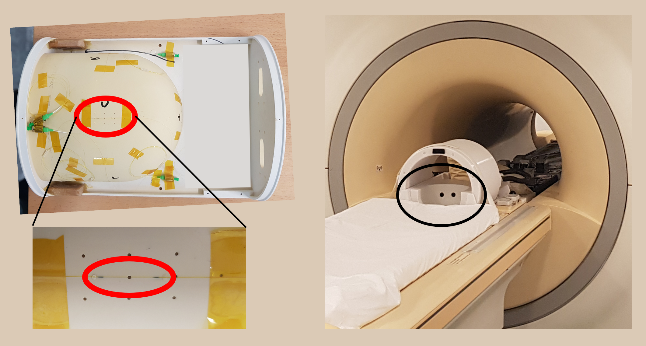
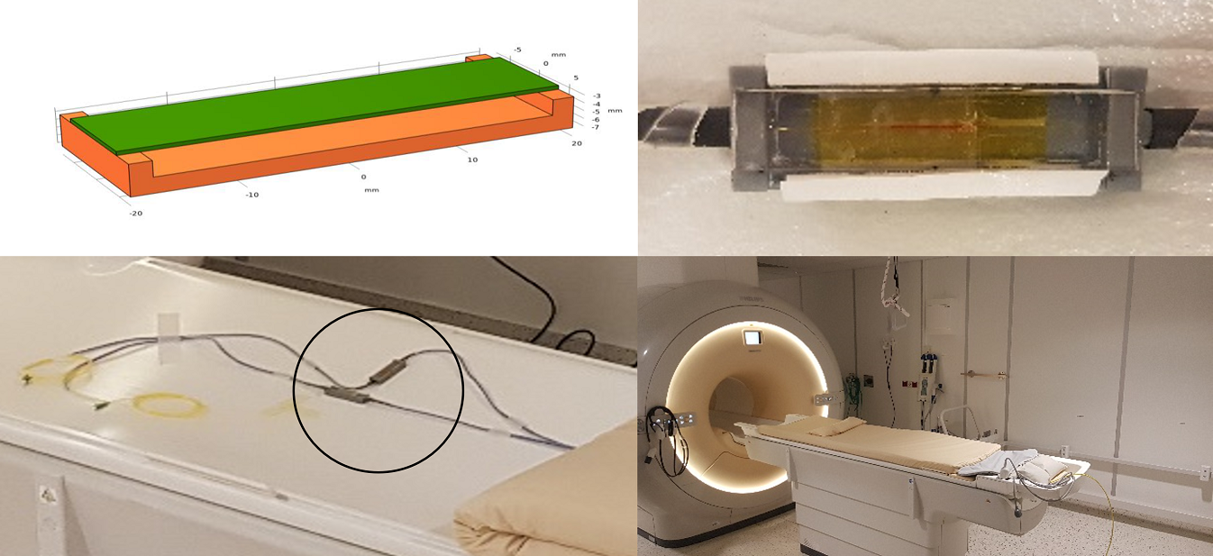
Methods FBGs were integrated into two parts of an MR-scanner (Philips, Best): a 7T head-coil and a 3T MR-bed. A single FBG was glued to the back of the headrest of a head-coil as shown in figure 1. Initial measurements were done outside the MRI with a subject lying on the floor on a towel in the headrest. For subsequent measurements a subject was lying with his head on a cushion in the headrest which was part of an 8 channel transceiver coil (figure1 right) which was used for imaging. Figure 2 shows two other FBGs which were integrated in a bending design and glued to the MR-bed below the standard matrass used for patient comfort. The scanners body coil was used for imaging in this case. An I4G 4 channel interrogator (Optics11, Amsterdam), located in the control room of the scanner, was connected at the end of approximately 24m optical fiber. Due to the high reflectivity of the FBG elements, a 5dB inline optical attenuator was used to prevent the FBG reflection spectra from saturation. FemtoSense 2.3 software (Optics11, Amsterdam) was used to acquire and store the data. The FBGs showed reflection peaks at ~1550nm (headrest) and ~1533nm and ~1539nm bending designs with no subject present. The sensitivity of the bending design FBGs was about 4 nm/kg, for the headrest sensor we could not measure the sensitivity due to the stiffness of the headrest material. With both setups several MR-scans were made to see the effect of scanning on the FBG signal. The standard peripheral pulse unit and respiratory belt signals of the scanner were acquired and used during a respiratory triggered T2 liver scan at 3T.Results & Discussion
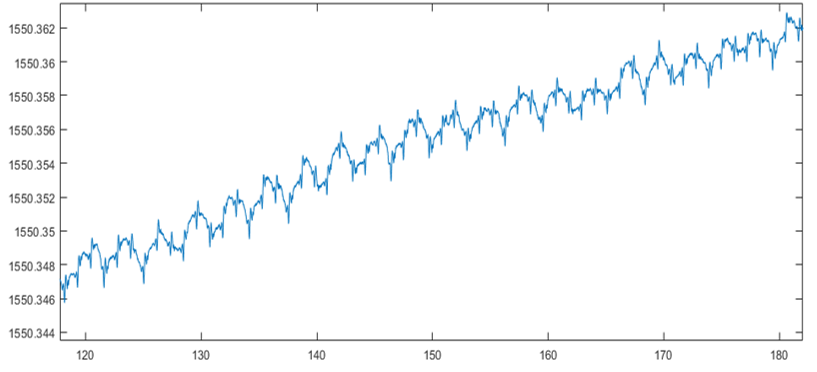
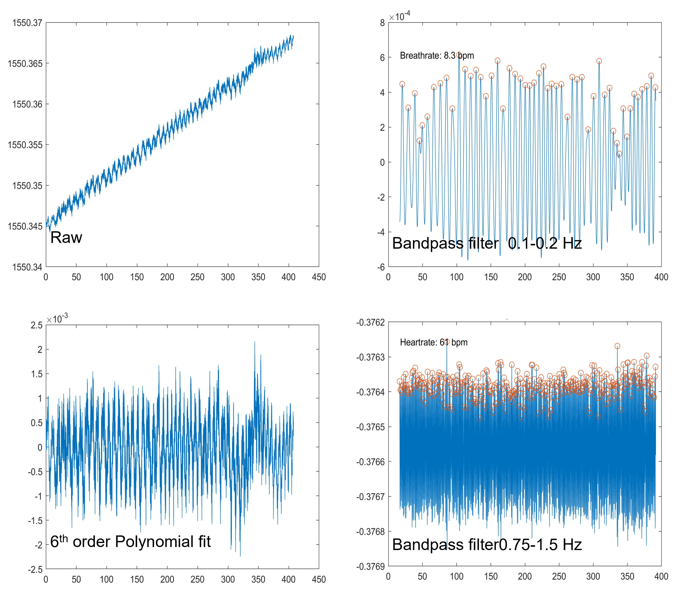
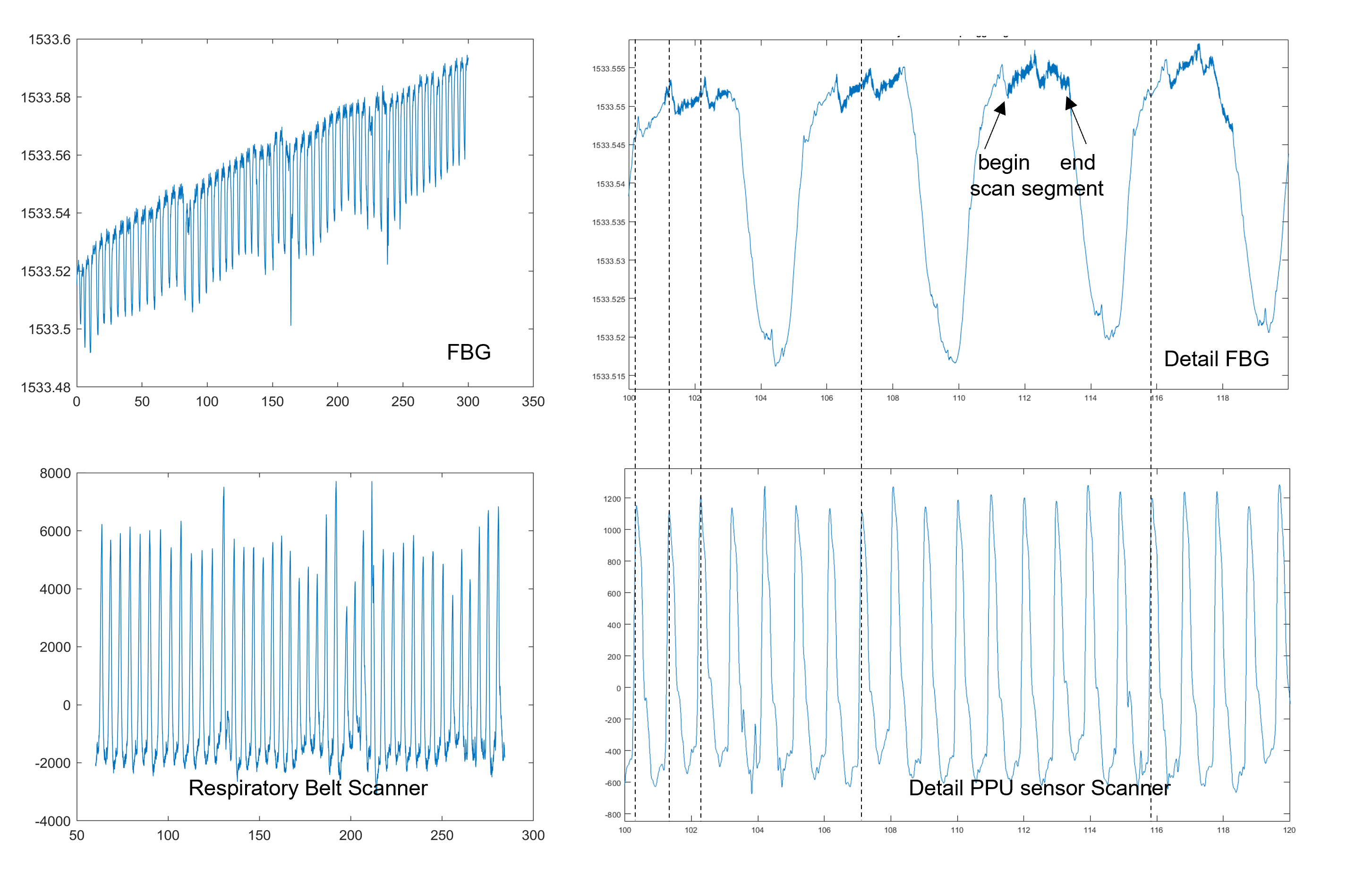
A raw signal trace from a subject lying on the floor in the headrest is shown in figure 3. Both the respiratory cycle and cardiac pulsation (small spikes) are clearly visible. The slow drift observed in the data is probably due to the warming up of the sensor due to the presence of the subject. A raw signal trace acquired during a T1 3D TFE sequence is shown in figure 4 together with results obtained after filtering. The arrows indicate the begin and end of scanning. The sound of the sequence is easily recognized when playing an mp4 file created from the polynomial fitted signal. A Fourier transform of the signal (not shown) also shows the main gradient switching frequencies in the MR-scan. Figure 5 shows data from an FBG beding design sensor glued on the table during a respiratory gated (by the belt) T2 liver scan. Again the scan segments can be recognized and there is good alignment between the belt and FBG data. Cardiac pulses are also visible but alignment with the PPU is somewhat variable (dotted lines).Conclusion & Outlook
The initial results shown in this work demonstrate that FBG sensors integrated into parts of the MR-scanner are sensitive enough to pick up vital signs. The comparison with standard MR sensors needs further investigation, especially the comparison with ECG. Realtime filtering of the FBG signals is required to use the FBG signal for cardiac and respiratory triggering of the scanner. Real time wavelet based filters [4] are currently being explored and implemented for this purpose.Acknowledgements
No acknowledgement found.References
[1] Łukasz Dziuda et al. Journal of Biomedical Optics 2013, 18(5) 057006
[2] Mariusz Krej et al. Biomedical Optics Express 2021 ,12/1, 7791
[3] Jan Nedoma et al. Sensors 2019, 19, 470
[4] Lukas P. A. Arts and Egon. L. van den Broek. Nature Computational Science, VOL 2, January 2022, 47–58
Figures