1417
High linearity non-magnetic RF power amplifier for 5T MRI1Paul C. Lauterbur Imaging Research Center, Shenzhen Institutes of Advanced Technology, Chinese Academy of Sciences, Shenzhen, China, 2Key Laboratory for Magnetic Resonance and Multimodality Imaging of Guangdong Province, Shenzhen, China, 3Chongqing University of Technology, Chongqing, China, 4National Innovation Center for Advance Medical Devices, Shenzhen, China, 5Department of Biomedical Engineering, State University of New York at Buffalo, Buffalo, NY, United States, 6United Imaging Healthcare, Shanghai, China
Synopsis
Keywords: RF Arrays & Systems, RF Arrays & Systems
Motivation: Accurate RF excitation in MRI requires a linear response from the radio-frequency power amplifier (RFPA). However, the conventional RF power amplifier (RFPA) used in MRI is typically located in the equipment room, which introduces complexity and significant signal losses. Additionally, it poses challenges to direct control of RF signals at the RF coil side.
Goal(s): Design high power and high linearity RFPA which can operate in a strong magnetic field environment.
Approach: The design incorporates non-magnetic high-power circuits and a negative feedback control module.
Results: The amplifier exhibits high power and linearity characteristics during the bench testing.
Impact: The proposed design method for non-magnetic RFPA can enhance the efficiency and linearity of RF excitation in MRI, multiple non-magnetic RFPAs will be fabricated to facilitate parallel transmission in 5T MRI.
Introduction
High field MRI offers unique opportunities for clinical research due to the high signal-to-noise ratio (SNR) and accelerated imaging speed [1]. In MRI, the RFPA generates RF pulses driving the transmit coil to produce polarized RF magnetic field (B1) within the patient. MRI requires linear response from RFPA for accurate RF excitation[2]. The RF power requirement for the same flip-angle increases with the magnitude of the static field, resulting in high power demand from RFPA in high field MRI [3], [4].However, it should be noted that typically over 30% of the RF power is dissipated within the lengthy cables between RFPA and RF coils. The gain of the power devices exhibits significant nonlinearity across a wide dynamic range of output power, resulting in distortion of the output waveforms.This study presents a high linearity non-magnetic RFPA that is capable of operating within the scanning room. With this design, lengthy cables are unnecessary since RFPA can be positioned adjacent to the RF coils, the power modules within the amplifier exhibit high consistency in order to minimize power loss in the combiner. An analog negative feedback control system is designed to compensate the nonlinearity of the amplifier.
Methods
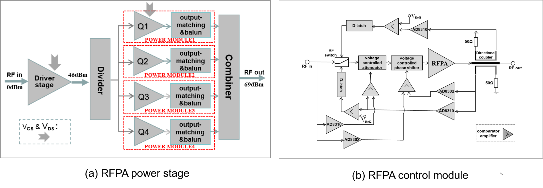
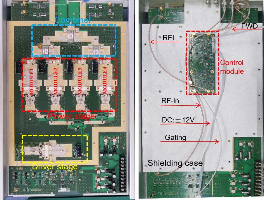
To achieve an output power of 8kW, we have implemented a multi-stage parallel amplification structure, as illustrated in figure 1(a). The power generated by the driver stage is evenly distributed to 4 identical power modules via a 1-4 power divider [5]. After impedance transformation and output matching through a non-magnetic plane Balun, the power from the 4 modules is combined using a power combiner. The matching of each power module is debugged and optimized in order to minimize loss in the combiner, ensuring a consistent high performance. The optimization objective is to maintain an amplitude difference within 1dB and a phase difference not exceeding 5°.The analog negative feedback control module facilitates the correction of nonlinear distortion and output protection, as illustrated in figure 1 (b). The control module comprises the amplitude, phase, and output protection control loops. The RFPA's output signal is monitored through a directional coupler and subsequently converted into corresponding voltage signals for amplitude and phase analysis using AD8310 and AD8302. The monitoring signal is compared with reference voltages (VRef1 & VRef2), triggering the D-latch to turn off the RF input signal in case of an abnormal state. The amplitude and phase of the output monitoring signal are simultaneously compared with those of the input RF signal, enabling the amplified error value to regulate both the voltage controlled attenuator and phase shifter. This facilitates nonlinear correction of the RFPA. The photograph illustrating the RFPA is presented in figure 2.Results
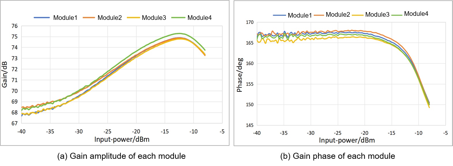
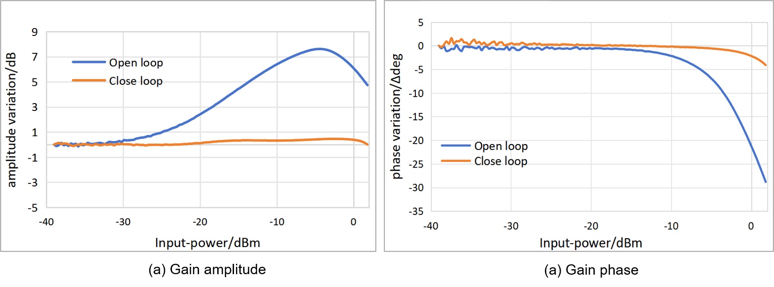
The amplitude and phase difference of each power module's output are effectively constrained within a narrow range during full power operation at 8kW by means of meticulous debugging, as illustrated in Figure 3. The amplitude difference of each channel is within 0.8dB, while the phase difference does not exceed 3°.The gain linearity test results for the RFPA are depicted in figure 4. When RFPA is operating in an open loop with frequency of 210.8MHz, the gain magnitude/phase fluctuation within 40dB dynamic range is more than 10dB/20°. The analog feedback control module significantly optimizes gain linearity, resulting in a gain fluctuation of less than 0.5dB/6° when feedback control is enabled.
Conclusion
This study presents design of an non-magnetic RF power amplifier for 5T MRI with an 8KW power capability, an analog negative feedback control system is designed to compensate the nonlinearity of the amplifier. The gain linearity specification of the commercial RFPA designed for 7T MRI (COMET, Switzerland) is less than 5dB, the gain/phase linearity specification of the commercial RFPA designed for 3T MRI (ANALOG, USA) is less 1dB/10°. While the gain/phase linearity of the non-magnetic RFPA proposed by this study is less than 0.5dB/6° when feedback control is enabled, ensuring high linearity across a wide dynamic range. Multiple non-magnetic RFPAs will be fabricated to facilitate parallel transmission in 5T MRI.Acknowledgements
This work was supported in part by the Project on Global Common Challenges of Chinese Academy of Sciences(No. 321GJHZ2022081GC),the NSFC grant (81627901), the Key Laboratory for Magnetic Resonance and Multimodality Imaging of Guangdong Province (2023B1212060052), the Funding Program of Shenzhen ,China (RCYX20200714114735123),the Chinese Academy of Sciences Youth Innovation Promotion Association funded project (Y2021098).References
1. Vachha B, Huang S Y. MRI with ultrahigh field strength and high-performance gradients: challenges and opportunities for clinical neuroimaging at 7 T and beyond[J]. European Radiology Experimental, 2021, 5(1): 1-18.2. Torres Chico G. RF power amplifier linearity compensation for MRI systems[D]. Massachusetts Institute of Technology, 2010.
3. Chen JF, Li Y, Zhang H, et al. High power RF amplifier for UHF MRI with configurable number of channels. ISMRM 2021 Abstract 1585.
4. J. T Vaughan et al, 7T vs. 4T: RF power, homogeneity, and signal-to-noise comparison in head images[J]. Magn Reson Med, 2001, 46(1): 24-30.
5. Wang J, Li Y, Liu S, et al. 8kw non-magnetic RF power amplifier with four-way combiner for 5T MRI. ISMRM 2023 Abstract 0270.
Figures