1415
An 8-Channel Transmit Array in Combination with a 31-Channel Receive Array for Human Brain Imaging at 11.7T1University of Glasgow, Glasgow, United Kingdom, 2University of Paris-Saclay, CEA, CNRS, BAOBAB, NeuroSpin, Gif sur Yvette, France
Synopsis
Keywords: RF Arrays & Systems, RF Arrays & Systems
Motivation: RF challenges increase with field strength, and novel RF coil solutions are essential to capture the potential benefits at 11.7T
Goal(s): To develop an efficient 8-channel transmit array in combination with a 31-channel receive array for whole brain MRI at 11.7T
Approach: Combined electromagnetic and RF pulse design simulations were performed. A folded-end RF shield was developed to minimise signal loss due to wave propagation. The receive array was optimally integrated to preserve the spatial distribution of the B1+ field.
Results: Whole-brain coverage was achieved with 8-channel transmit array and excellent agreement between simulation and measurements was observed.
Impact: Identifying the coil losses and engineering solutions to mitigate them provides substantial gains in transmit performance, especially at 11.7T where the losses due to radiation is high. This approach can be extended to transmit array designs at other field strengths.
Introduction
The newly operational 11.7T scanner at Neurospin (CEA, France) enables human MRI at an unprecedented field strength and promises a significant gain of signal-to-noise ratio1,2. However, RF losses scale up with field strength and optimal implementation of the RF coil is essential to extract the desired performance from the RF coils at 11.7T3. Furthermore, transmit arrays must be large enough to accommodate receive arrays and should provide efficient excitation across the whole brain with limited input power. In addition, optimal integration of the tight-fitting multi-channel receive array is essential to preserve the transmit performance. This work presents initial phantom results of an 8-channel transmit 31-channel receive head coil, a first of its kind at 11.7T.Methods
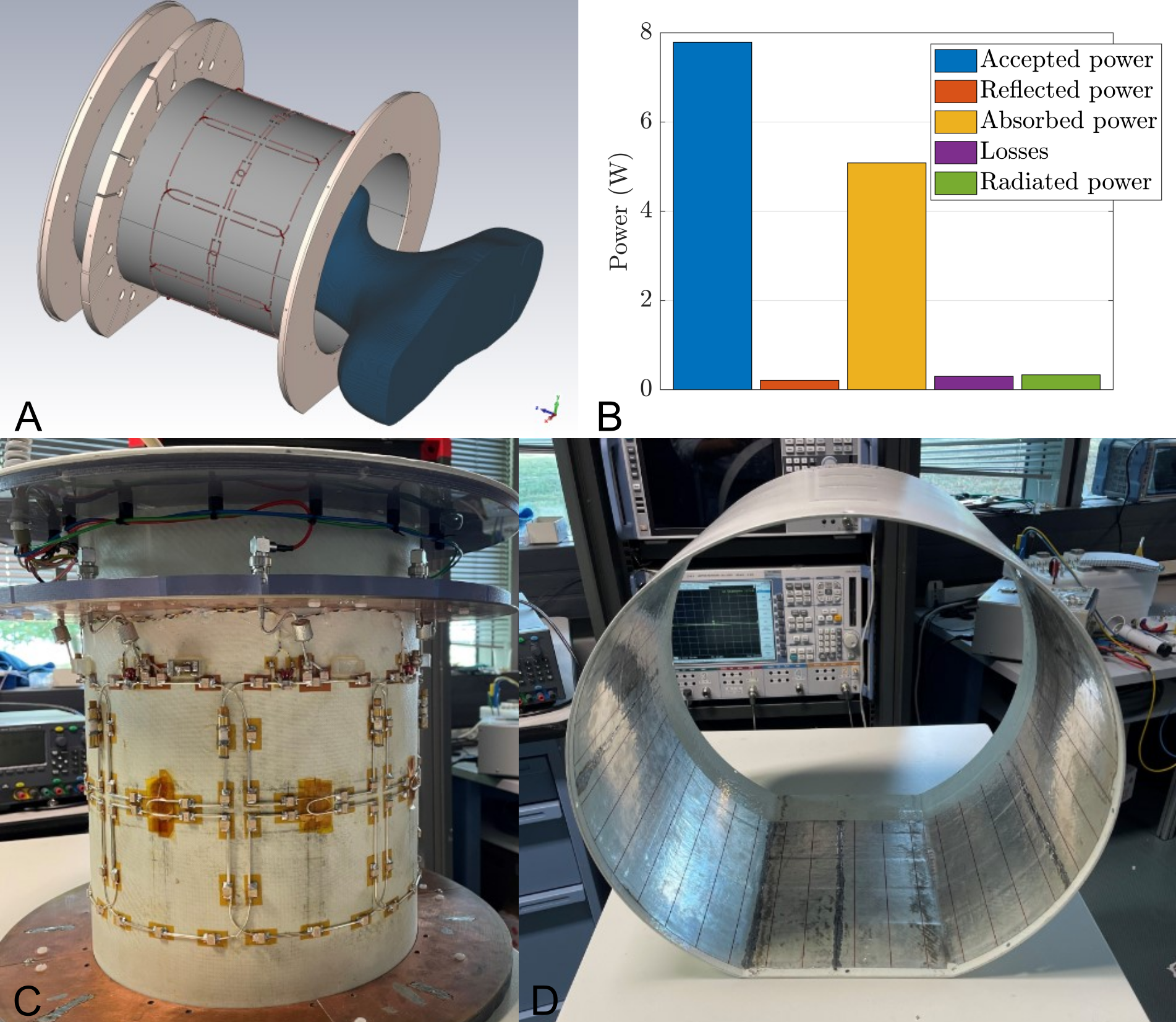
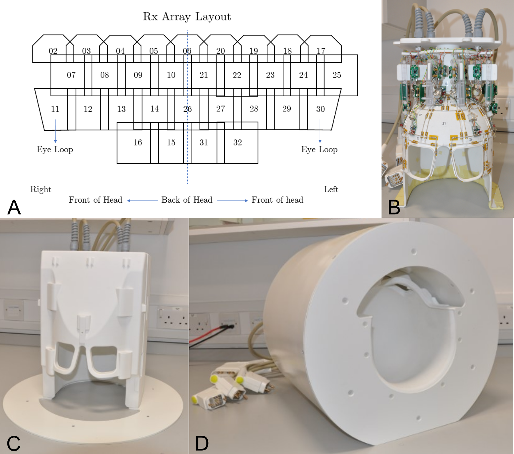
The transmit array optimisation workflow consisted of combining electromagnetic and RF pulse design simulations3. The numerical model consisted of the magnet bore and all losses due to dielectric, components, and cables (Fig. 1A). The coil was tuned and matched to a tissue-equivalent head-and-shoulder phantom. The transmit elements were arranged in a nested configuration4 in which the adjacent elements were geometrically overlapped, and the second-neighbouring element was also decoupled. There are 18 capacitors in each loop to tune it to 499.415MHz and the loop extended 180mm along the z-direction to achieve whole brain coverage (Fig. 1C). Radiation loss was minimised using a folded-end RF shield3 and a non-circular cross-section with a flat base was chosen so that the coil sits lower on the patient table (Fig. 1D).The receive array is based on the 9.4T array5, comprising 31 elements symmetrically arranged in four rows (Fig. 2A). There are 9 elements each in the first three rows and four elements in the fourth row. The receive array was constructed on a 3D printed helmet with internal dimensions comparable to the industry standard 32-channel 7T head coil (Fig. 2B). The fully assembled coil setup is shown in Fig. 2C and 2D.
Results and Discussion
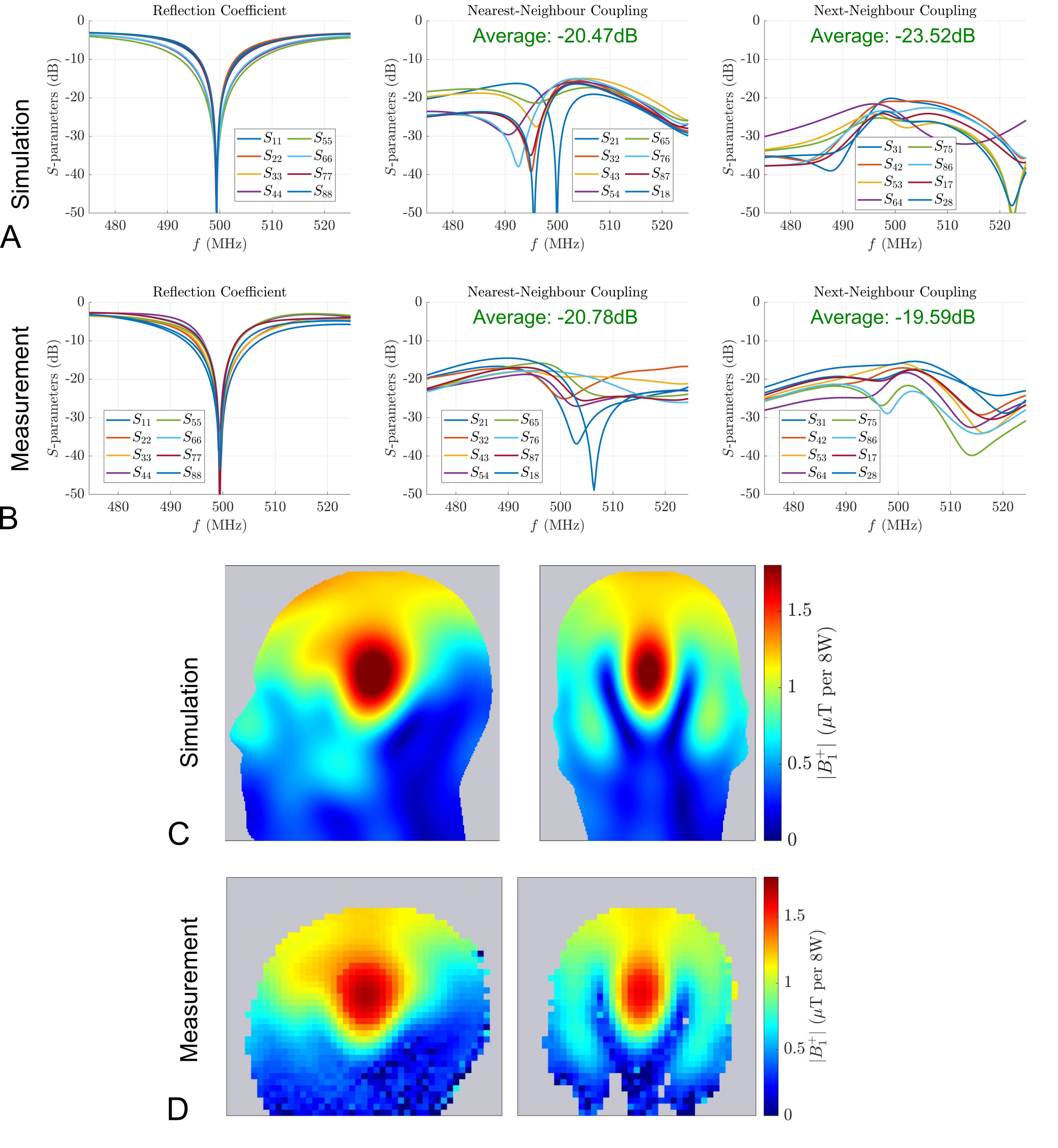
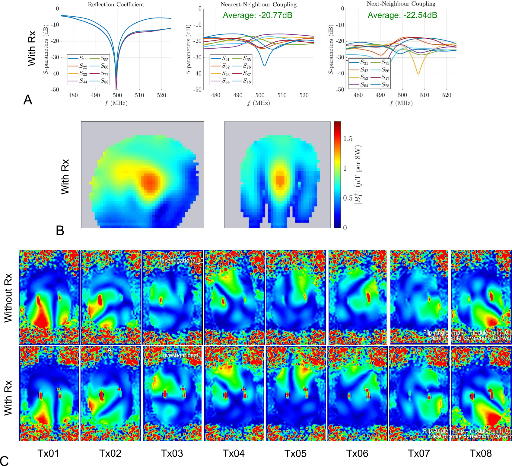
For the numerically optimised transmit array, the power loss due to radiation was 4%, and due to reflection caused by impedance mismatch and coupling was about 3% (Fig. 1B). Bench and scanner measurements of the transmit array in transceiver mode are shown in Fig. 3. The simulated and measured S-parameters (Fig. 3A and 3B) demonstrate that the coil elements were matched to better than -30dB, and the couplings between the adjacent and second-neighbouring elements were about -20dB. There was qualitative agreement in the spatial distribution of the simulated and measured CP-mode field maps shown in Fig. 3C and 3D.In the next step, the transmit array tuning was adjusted in the presence of the actively detuned receive array. All channels could be matched to better than -30dB and the coupling between the adjacent and next-neighbouring channels remained below -20dB (Fig. 4A), demonstrating minimal interaction with the receive array. It is important to note that the inter-element decoupling was not adjusted after inserting the receive array.
The peak B1+ in simulations was 2.0uT for 8W input power at the coil plug (Fig. 3C) whereas the corresponding measured value was 1.72uT (Fig. 3D), representing a 14% mismatch between the realised coil and the numerical model. Upon integrating the receive array, although there was good agreement in the spatial distribution of B1+, a total reduction of 16% was observed in its peak value, which was attributed to the shielding effect of the receive array (Fig. 4B). The measured single-channel field maps with and without the receive array are shown in Fig. 4C.
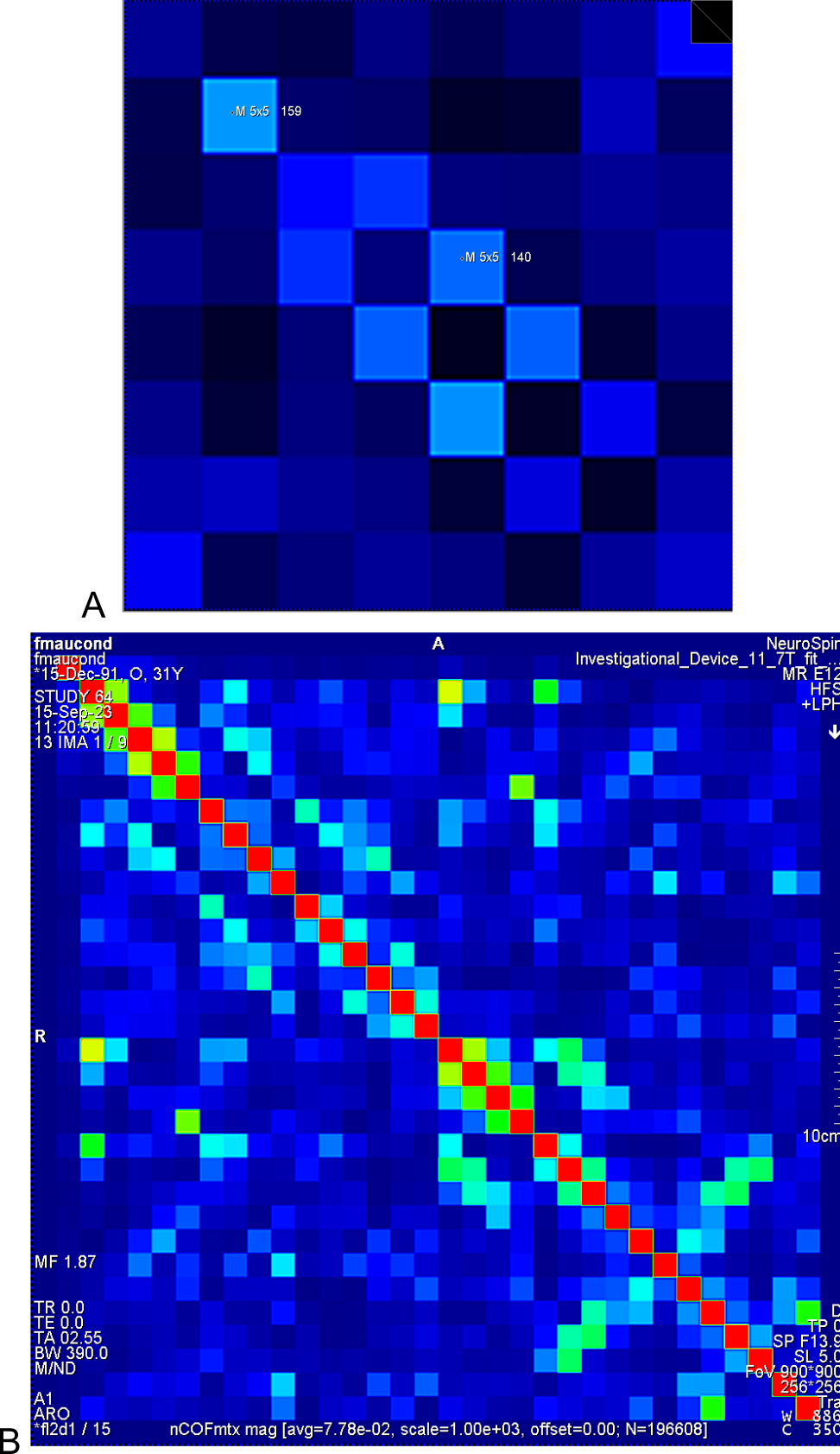
The matrix shown in Fig. 5A represents the robustness of the transmit array tuning as seen by the scanner, and this plot was generated from the directional coupler measurements while loading the coil with a much smaller phantom. In the receive array noise correlation matrix (Fig. 5B), the maximum correlation coefficient was about 0.4 between the receive elements in the vertex of the helmet.
We expect to receive approval for human imaging with this coil towards the end of 2024. Our immediate next goal is to estimate the SNR gained at 11.7T compared to the industry standard 7T head coil as both receive arrays were constructed on similar size helmets.
Conclusion
A state-of-the-art head coil for human brain imaging at 11.7T has been developed and initial phantom results have been presented. A more quantitative comparison of the coil performance and comparison with the standard 7T head coil is expected in the near future.Acknowledgements
This project has received funding from the European Union’s Horizon 2020 research and innovation programme under grant agreement No. 885876 (AROMA).References
- Le Ster C. et al. Magnetic field strength dependent SNR gain at the center of a spherical phantom and up to 11.7T. Magn Reson Med. 2022, 88(5), 2131-2138.
- Pohmann R. et al. Signal-to-noise ratio and MR tissue parameters in human brain imaging at 3, 7, and 9.4 tesla using current receive coil arrays. Magn Reson Med. 2016, 75(2), 801-809.
- Chu S. et al. Electromagnetic and RF pulse design simulation based optimization of an eight‐channel loop array for 11.7 T brain imaging. Magn. Reson. Med. 2023, 90(2), 770-783.
- Williams, S. et al. A nested eight-channel transmit array with open-face concept for human brain imaging at 7 Tesla. Frontiers in Physics 2021, 9 (701330).
- Shajan, G. et al. A 16-channel dual-row transmit array in combination with a 31-element receive array for human brain imaging at 9.4 T. Magn. Reson. Med. 2014, 71(2), 870-879.
Figures