1414
A size-adaptive RF coil with integrated NMR field probes for pediatric brain Imaging at 7 T1McConnell Brain Imaging Centre, Montreal Neurological Institute and Hospital, McGill University, Montreal, QC, Canada, 2Department of Neurology and Neurosurgery, McGill University, Montreal, QC, Canada, 3Department of Biomedical Engineering, McGill University, Montreal, QC, Canada, 4Siemens Healthcare Limited, Montreal, Montreal, QC, Canada
Synopsis
Keywords: RF Arrays & Systems, Pediatric, RF Coil, High Field MRI, 7T
Motivation: To develop a safe, size-adaptive RF head coil with an integrated commercial field monitoring system for pediatric imaging at 7T MRI.
Goal(s): Performance of the size-adaptive RF head coil was quantitatively evaluated and compared to that of a commercial receive adult head coil (Nova Medical).
Approach: The coil performance was evaluated at the largest and smallest dimensions of the receive former, with and without integrated field probes.
Results: Simulations of transmit coil demonstrated that the coil is safe for pediatric imaging of subjects below 30 kg at 7T. The SNR performance of the coil was comparable to the commercial coil.
Impact: The eight channel dipole transmit and 32 channel size-adaptive receive array with integrated 16 NMR commercial field monitoring probes for imaging pediatric (4-9 years old) brain at 7T enables safe and high-quality imaging of subjects below 30 kg at 7T.
Introduction
Pediatric imaging at ultrahigh field (UHF) is challenging because of the reduced size of the transmit coil, SAR considerations, B1+ inhomogeneity and radiofrequency (RF) penetration depth.The present work evaluates the design, construction and testing of an eight-channel dipole transmit array and 32 channel size-adaptive receive array with integrated magnetic field monitoring, using the Skope Clip-On Camera (Skope Magnetic Resonance Technologies), for pediatric (4-9 years old) neuroimaging at 7T.
Materials and Methods
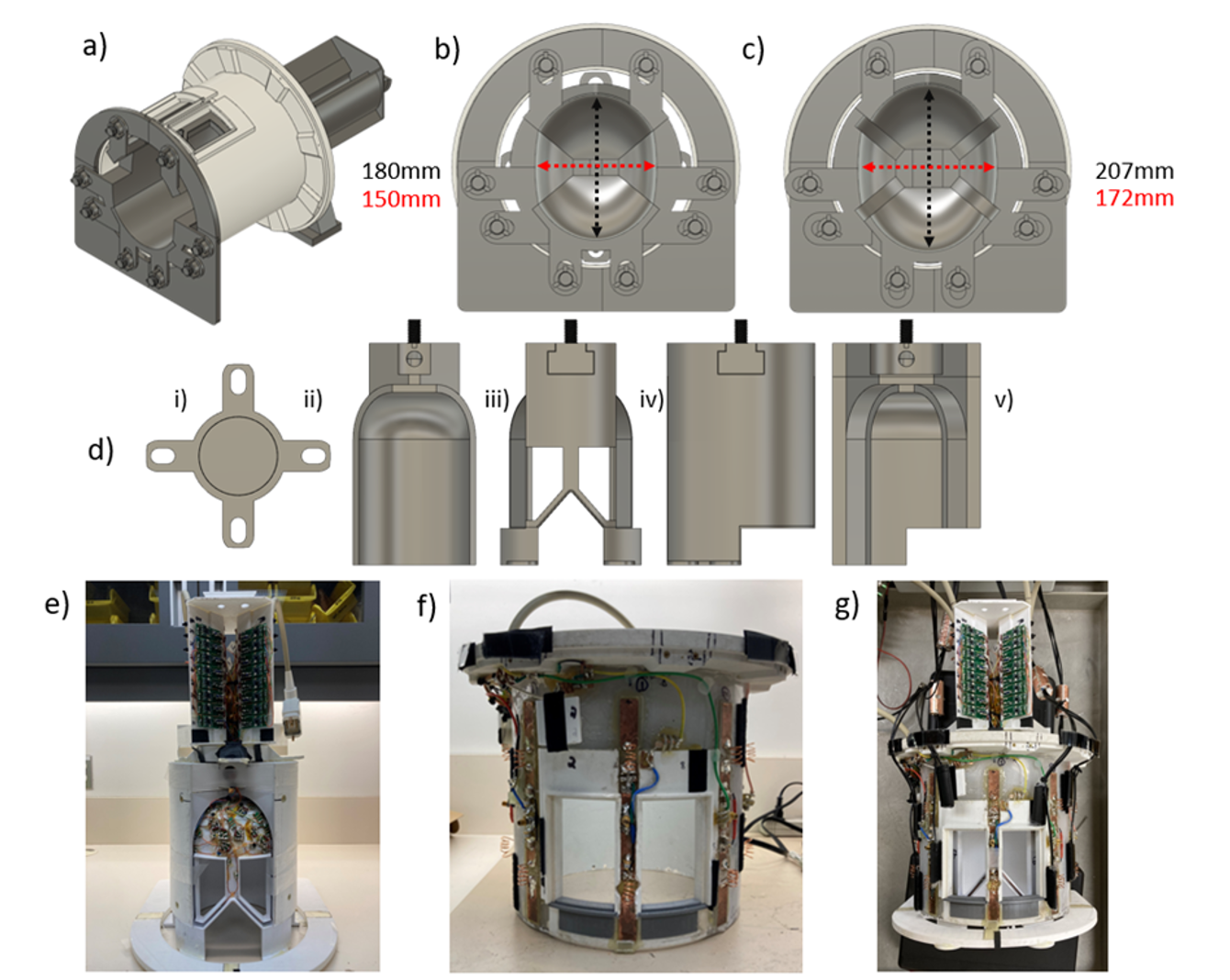
Coil housing: The coil housing consisted of two mechanical systems: (i) a rigid Tx housing and (ii) a size-adjustable Rx former (Figure 1.a). The cylindrical housing had an outer diameter of 356 mm, the inner diameter of 240 mm and a total height of 270 mm. The Rx coil housing was comprised of five physically separable mechanical components, one each for the anterior, posterior, left, right and superior regions of the head (Figure 1.d). In the anterior-posterior direction, the minimum and maximum achievable dimensions were 180 and 207 mm (Figure 1.b, Fig 1.c).Transmit Coil: The transmit coil was comprised of eight dipoles offset by 45⁰ to provide full coverage of the head (Figure 1.f). The dipoles were tuned and matched to 297.2 MHz. The low-footprint design of dipole antennas allowed positioning the Skope Clip-On Camera NMR field probes. The performance of the dipoles was simulated in CST Microwave Studio (CST) to determine B1+ efficiency and SAR.
Receive Array: The receive coil consisted of 32 loop elements (Figure 1.e) ranging in diameter from 6 to 12 cm. Elements on each piece of the former were geometrically decoupled. Three safety factors were also integrated into the design of the receive loop circuitry: Active detuning, Passive detuning and Fuses. Receive elements were connected to WMM7RP preamplifiers (WanTCom) via coaxial cables. Cable traps were placed along the coaxial cables and the receive loops were further preamplifier decoupled.
Field Probes: A commercial field monitoring system, the Skope Clip-On Camera, was integrated with the coil housing. The Clip-On Camera system consisted of 16 19F based NMR field probes. In our work, all probes were placed on the outer surface of the transmit former between dipoles (not between the transmit and receive housing like [1,2, 3]).
Results and Discussions
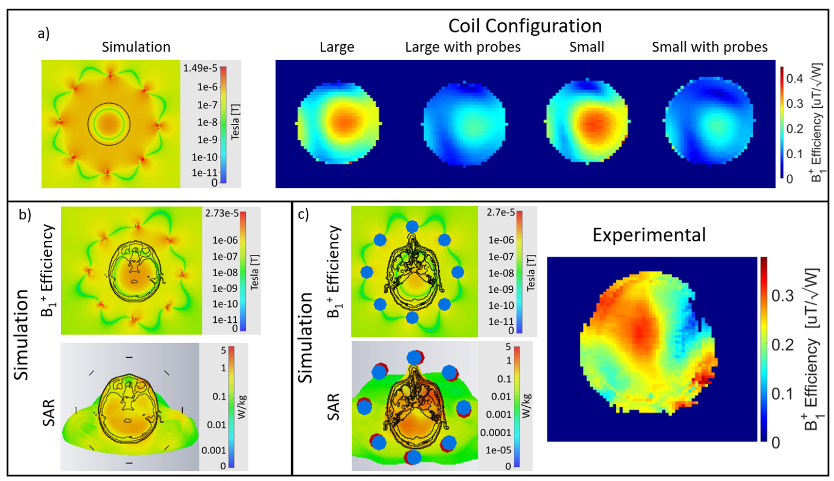
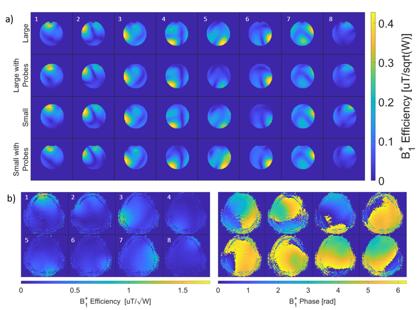
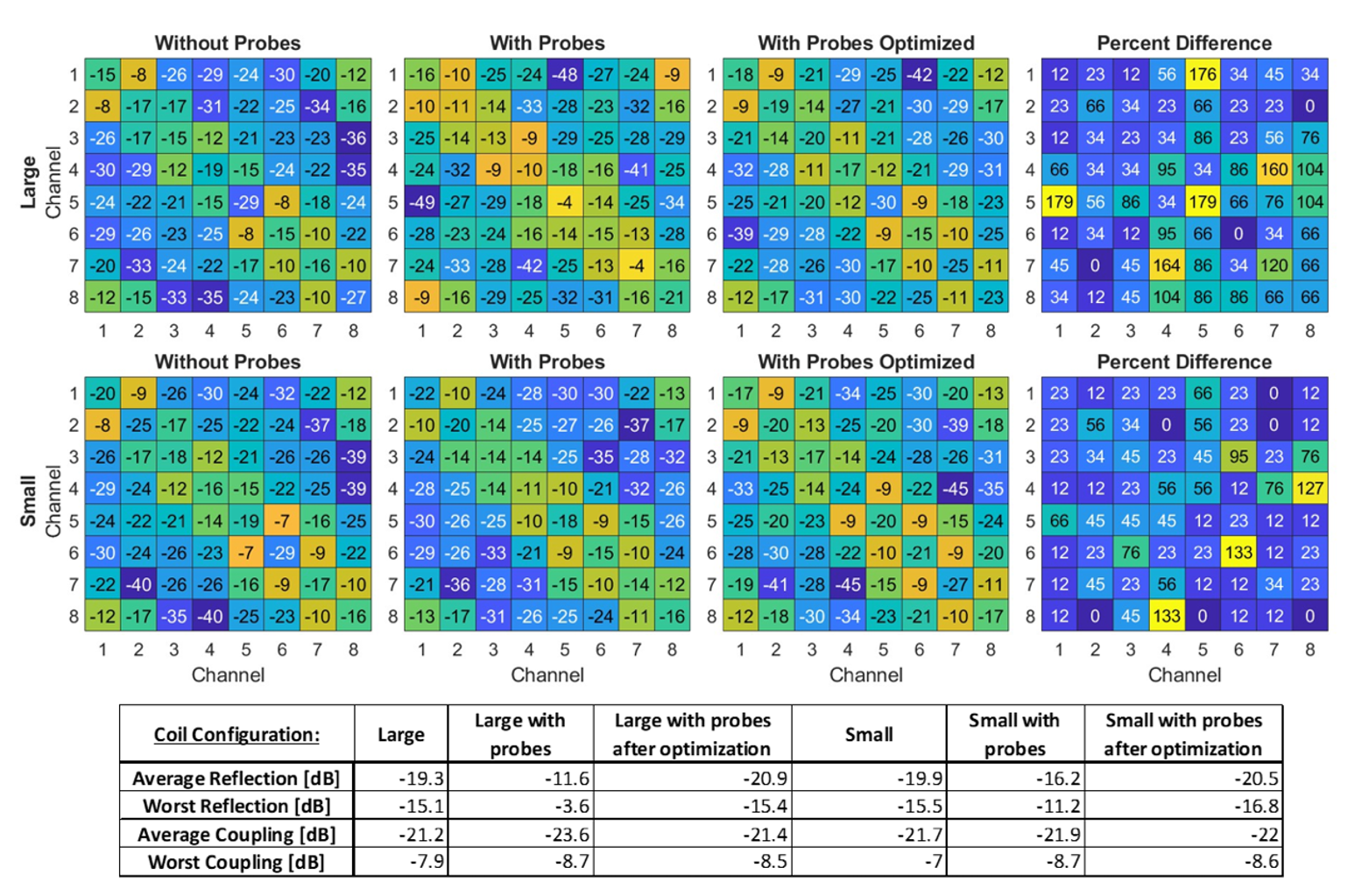
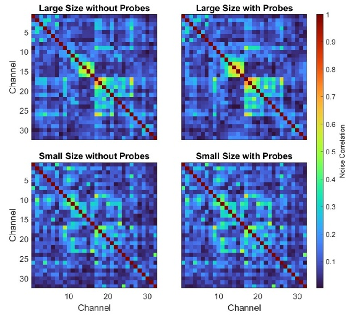
Transmit Coil: After tuning and matching all dipole elements at 297.2 MHz, all channels had an S11 reflection coefficient better than -22dB. The worst-case coupling S21 was -11dB. Transmit efficiency and SAR simulation results from CST are shown in Figure 2. This figure also includes experimentally generated B1+ efficiency maps acquired in both the phantom and in a healthy adult human subject. Figure 3 shows B1+ efficiency maps for individual Tx channels measured experimentally in the phantom at the largest and smallest size of the Rx former, with and without field probes, as well as B1+ magnitude and phase maps measured experimentally in vivo. Scattering matrix parameters for all coil configurations, with and without integrated field probes, are given in Figure 4, along with a table summarizing the key results.Receive Coil: The mean coupling between receive elements was -16 dB. The Q ratio for the representative Rx element was 6.3. Noise correlation matrices for the coil at its largest and smallest size, with and without field probes, are given in Figure 5 (measured in scanner).
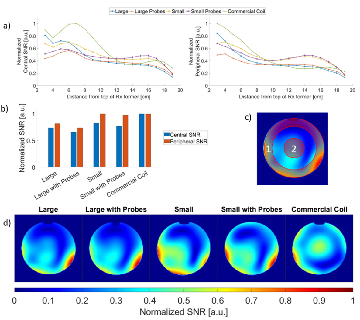
Phantom SNR maps for a representative slice near the center of the brain are shown in Figure 6. Central SNR was determined by taking the mean value of a 40mm diameter circular ROI at the center of each slice.
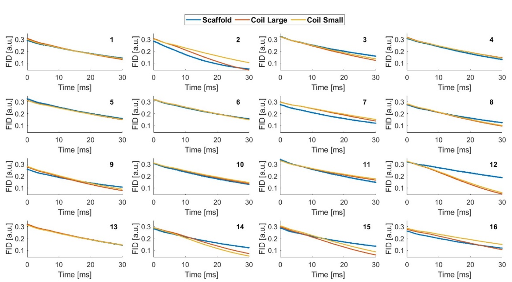
NMR Probe Performance: The magnitude free induction decay signals of each probe measured on the manufacturer’s scaffold and when integrated with the coil in its largest and smallest configuration are shown in Figure 7.
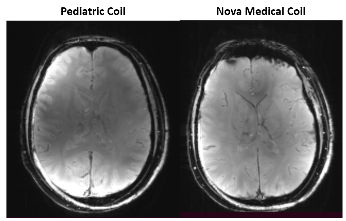
Figure 8 shows in vivo 2D spoiled gradient echo images of a 33-year-old, healthy adult human subject (left: using the pediatric coil at its largest size, right: the same subject using commercial Nova coil).
Conclusion
Compared to the Nova commercial head coil, our pediatric coil exhibited similar uniform SNR over the length of the Rx array in the phantom imaging experiments. This was true for both the large and small sizes of the coil. ROI-derived central and peripheral SNR at the top of the sensitive region of the Rx former (i.e., in the region corresponding to the top of brain) were higher for the Nova coil by 34% and 18%, respectively, compared to the coil at its smallest size.The performance of the coil was impacted by the integration of the NMR field probes, with observed reductions in SNR and B1+ efficiency.
Acknowledgements
We would like to thank Paul Weavers and Cameron Cushing from Skope Magnetic Resonance Technologies for their helpful insights. Funding support for the present work was provided by the Transforming Autism Care Consortium, the Natural Sciences and Engineering Research Council of Canada and the McGill Healthy Brains Healthy Lives Initiative.
We thank also Kyle M. Gilbert (Centre for Functional and Metabolic Mapping, Western University, London, ON, Canada) for his valuable support.
References
[1] Duerst Y, Wilm BJ, Dietrich BE, et al. Real-time feedback for spatiotemporal field stabilization in MR systems. Magnetic Resonance in Medicine. 2015;73(2):884-893. doi:10.1002/mrm.25167
[2] Gilbert KM, Dubovan PI, Gati JS, Menon RS, Baron CA. Integration of an RF coil and commercial field camera for ultrahigh‐field MRI. Magnetic Resonance in Med. 2022;87(5):2551-2565. doi:10.1002/mrm.29130
[3] Barmet C, Zanche ND, Pruessmann KP. Spatiotemporal magnetic field monitoring for MR. Magnetic Resonance in Medicine. 2008;60(1):187-197. doi:10.1002/mrm.21603
Figures