1412
An 8-channel transceiver and 56-channel receive array for combined brain and c-spine imaging at 7 tesla1Imaging Centre of Excellence, University of Glasgow, Glasgow, Scotland, 2MRI Physics, NHS Greater Glasgow and Clyde, Glasgow, Scotland, 3Siemens Healthcare Ltd, Camberley, United Kingdom, 4Department of Clinical Radiology, NHS Greater Glasgow and Clyde, Glasgow, Scotland, 5MR CoilTech Limited, Glasgow, Scotland
Synopsis
Keywords: High-Field MRI, High-Field MRI, Radiofrequency coil, Neurovascular imaging
Motivation: Current methods for neuroimaging at 7T require separate coils for brain and c-spine imaging or rely on a 16-channel transmission setup for combined imaging.
Goal(s): To develop a neurovascular (NV) coil with eight transmit channels (industry standard) with extended longitudinal coverage from the brain to the neck region.
Approach: Based on coupled electromagnetic and circuit optimization, a modified coil configuration with six-upper and two-lower transceiver elements was constructed and integrated with a 56-channel receive array.
Results: Measurements in vivo suggest that the proposed NV coil delivers diagnostic-quality images of the brain and spinal cord in a single acquisition.
Impact: The 7T neurovascular coil, designed for concurrent brain and c-spine imaging, will extend the high-resolution capability of 7T-MRI to the routine diagnosis of diseases affecting soft tissues and vessels in the head and neck regions in clinical practice.
Introduction
In the field of neuroimaging, 7T MRI has received significant attention due to its increased resolution and signal-to-noise ratio (SNR) with the potential to enhance the early diagnosis of subtle pathologies. To match clinical practice at 1.5T and 3T, there is a demand for concurrent imaging of the brain and c-spine at 7T. In previous work, a 16-channel transmit, 64-channel receive array [1] and a 16-channel transceiver loop array [2] have been developed for this purpose. To explore a solution for standard 7T MRI systems equipped with eight transmit channels, an 8-channel transceiver array has also been proposed and its ability to simultaneously image the head and neck has been demonstrated [3]. In the current study, this array has been combined with a 56-channel receiver array to enhance the SNR and parallel-imaging capabilities of the neurovascular (NV) coil. The transmit and anatomical performance of the constructed 8TxRx56Rx NV coil was validated in phantoms and in vivo using a static B1 shim.Methods
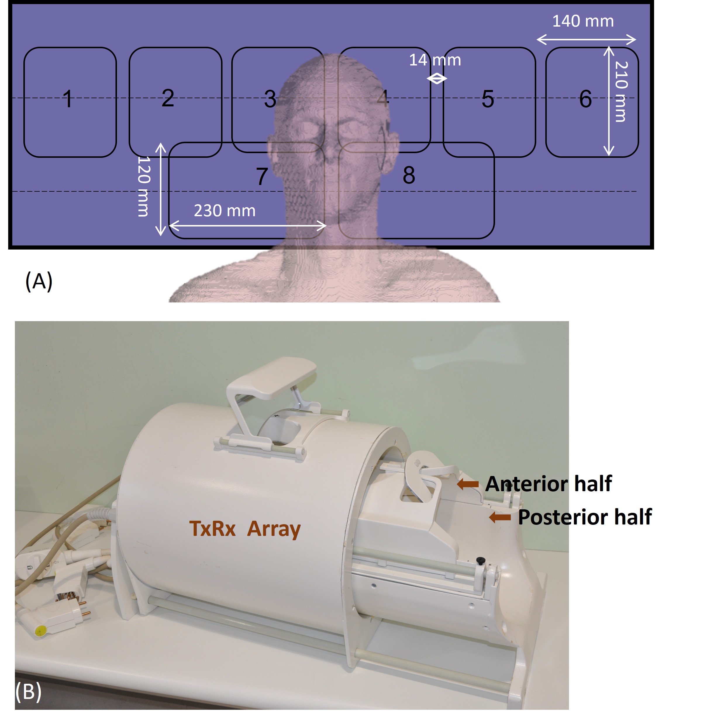
The dual-row transceiver array comprises eight radiating loops (TxRx) organized in a cylindrical configuration around a fiberglass tube (εr=4.3; tan δ=0.025) of inner diameter 290 mm. The array is structured with six elements in the upper row and two elements in the lower row. The optimization of the 8TxRx array was performed using CST Studio Suite 2021 (Dassault Systems, France). The array was used in transmit mode with a static B1 shim in which the relative phase difference between the top six elements was set at 60°, and the phase of the lower two channels was optimized to maximize the distribution of the B1+ field in the neck region without compromising the field distribution in the head region.To minimize the coupling between the large transceiver loops and the receive loops in receive mode, the phase between the input circuit and TR switches was adjusted to achieve pre-amplifier decoupling. The 56-channel receive array was based on previous work [4] and assembled on a closely fitting split-top helmet in multiple rows, incorporating 16 channels in the anterior half and 40 channels in the posterior half.
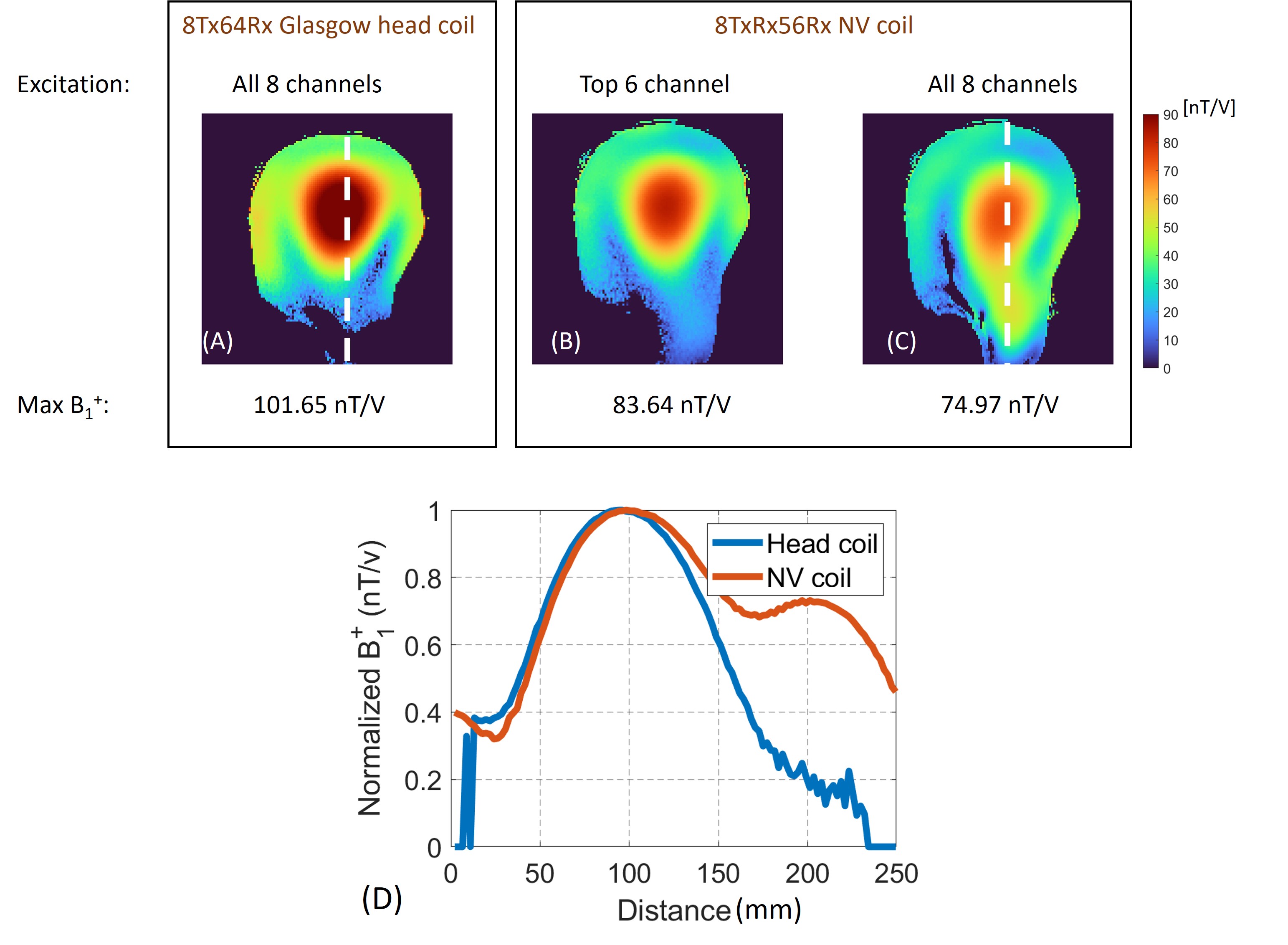
The finalized assembly, as depicted in Figure 1(B), was tuned, and matched to a head-shoulder phantom filled with a tissue-equivalent solution (εr= 52.1, σ = 0.41 S/m). Bench measurements and MR measurements were conducted using a vector network analyser (Rohde & Schwarz, Germany) and a Magnetom Terra 7T whole-body scanner (Siemens Healthcare, Erlangen, Germany), respectively. The transmit efficiency of the constructed coil was validated on the phantom while exciting: (1) all 8 channels, and (2) the top 6 channels only, this was compared with the efficiency of an 8Tx64Rx head coil [5]. Measurements on healthy subjects in vivo were carried out after approvals from local safety and ethics committees.
Results and Discussion
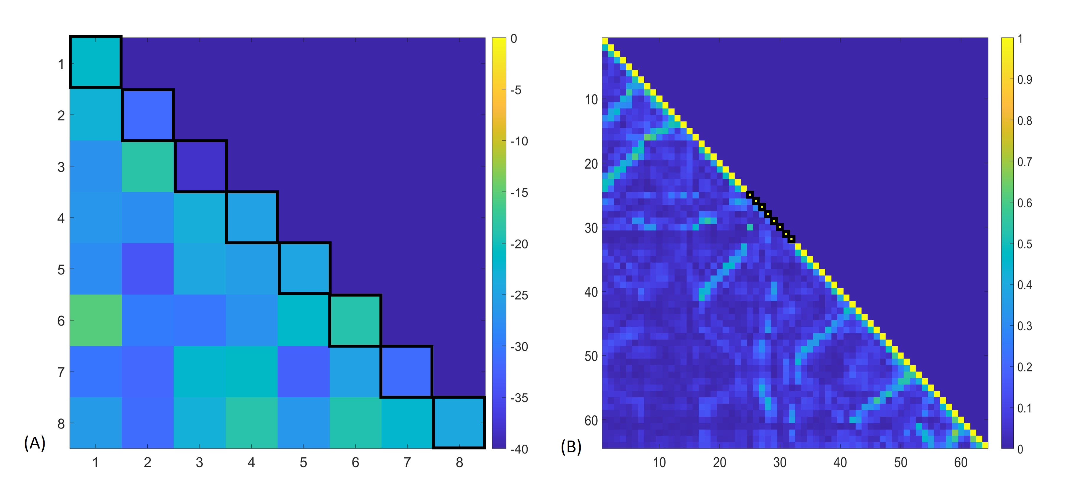
Figure 2 displays the measured S-parameter matrix of the transceiver elements, as well as the noise correlation matrix of the 64-channel receive array when loaded with the phantom. The inter-element coupling in the 8TxRx array ranged from -15.46 dB to -38.1 dB, whereas the noise correlation of the off-diagonal elements of the receiver array ranged from 0.04% to 67.5%, with an average of 12.6%.Figures 3A-3C compares the measured B1+ efficiency of the proposed NV coil in the phantom with that of the 8Tx64Rx head coil. The efficiency of the NV coil, when using the six top-row elements only, was found to be 17.7% lower than that of the 8Tx head coil. Figure 3D compares the normalized B1+ of the coils, plotted across the center of the phantom, clearly demonstrating the extended FOV of the NV coil.
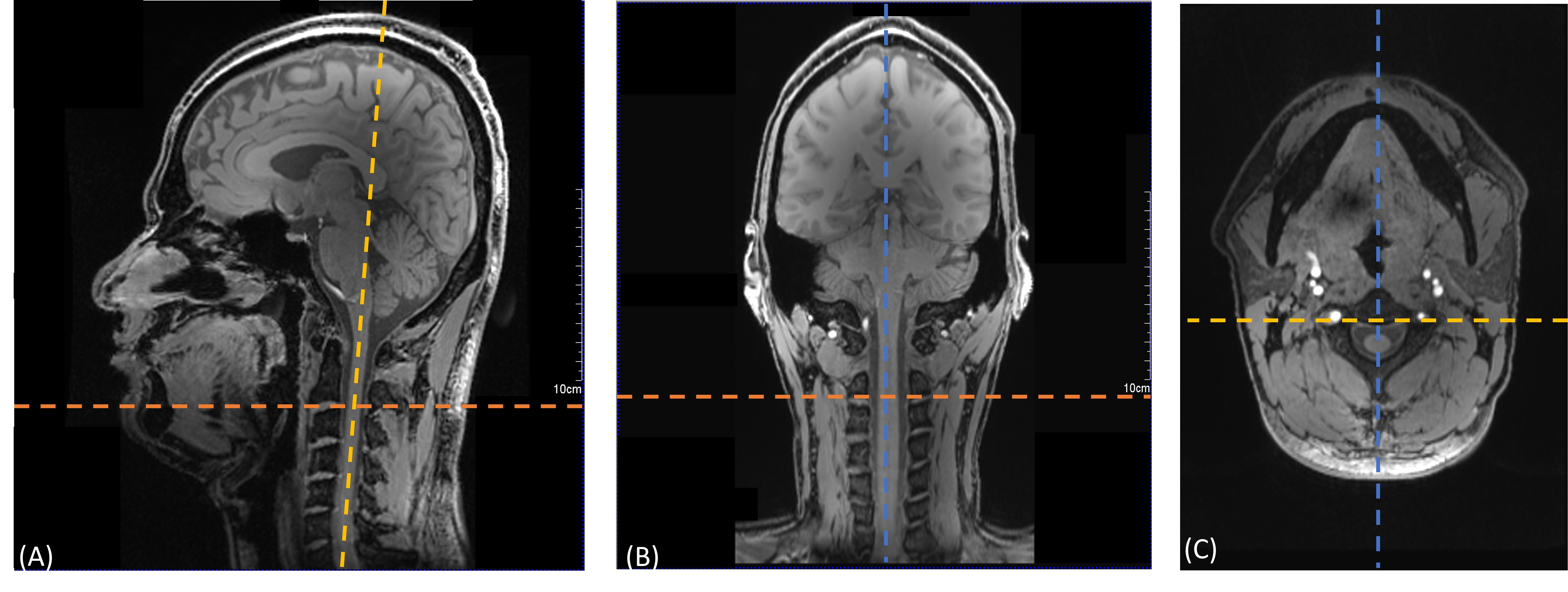
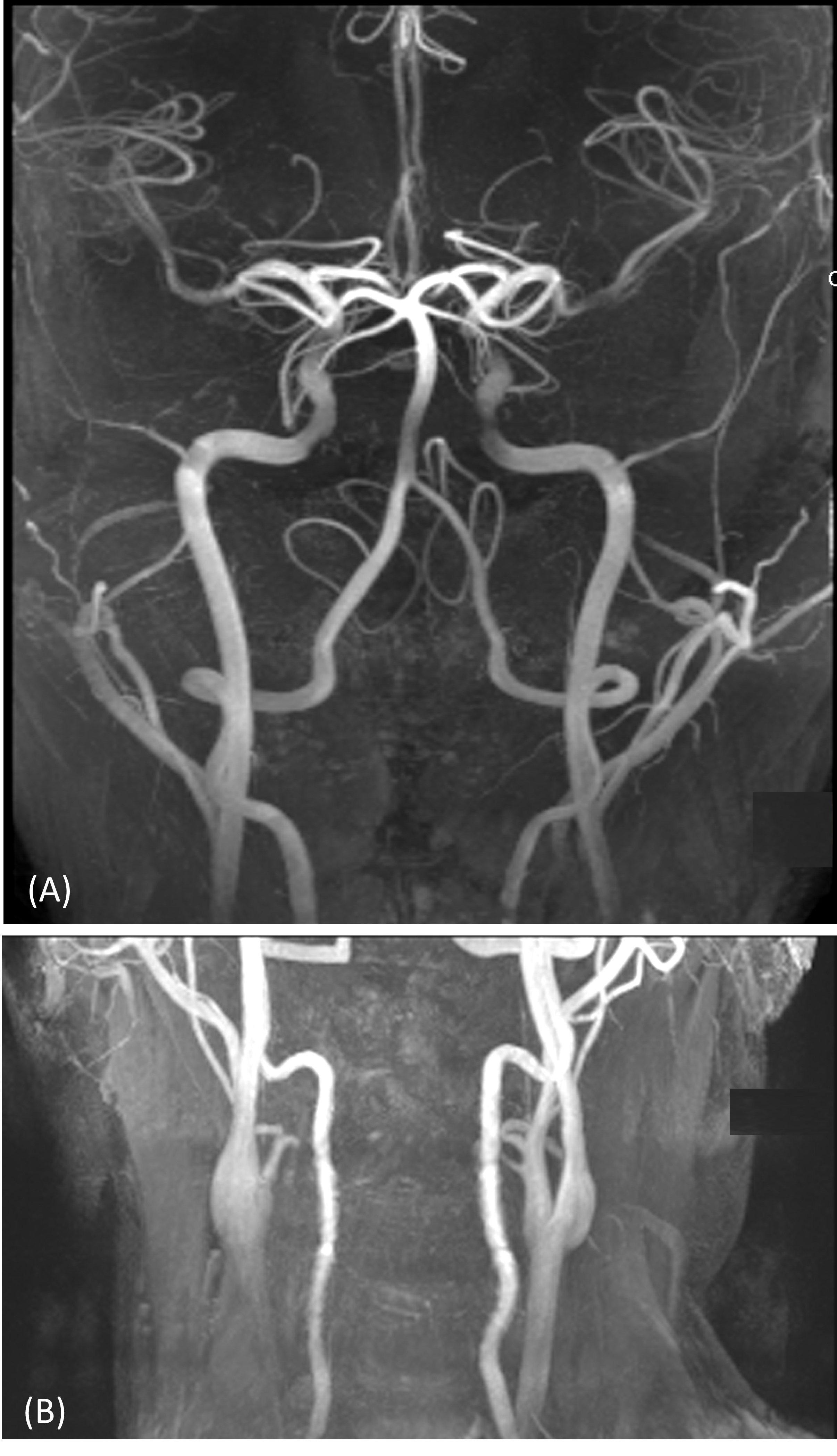
High-resolution FLASH images and time-of-flight (TOF) maximum intensity projections (MIPs) acquired with the 8TxRx56Rx NV coil are shown in Figures 4 and 5, respectively. The anatomical images demonstrate high SNR and an even contrast and signal level across the extended imaging region of the NV coil despite the static B1+ shim, which was not optimized on subject-specific basis. The TOF data demonstrate good coverage of intra- and extra-cranial vessels, which extends to below the carotid bifurcation in preliminary studies.
Conclusion
This study has demonstrated the efficacy of the proposed 8TxRx56Rx NV coil design in producing high-resolution, diagnostic-quality images encompassing the entire brain and lower neck region. The increased coverage compared to existing 8Tx head coils promises to improve the clinical application of the current generation of pTx 7T MRI systems with eight transmit channels. Future work will explore the RF shimming and pTx capabilities of the coil and quantify the SNR and parallel-imaging performance of the coil.Acknowledgements
This project is funded by SINAPSE, the Christine Rodgers endowment fund, the Neuroscience Foundation, and the UKRI strength in places fund. We are grateful to Tracey Hopkins and Rosie Woodward for their support with the human imaging parts of this study.References
[1] M. W. May et al., "A patient-friendly 16-channel transmit/64-channel receive coil array for combined head-neck MRI at 7 Tesla," Magn Reson Med, vol. 88, no. 3, pp. 1419-1433, Sep 2022.
[2] Bei Zhang et al., "Simultaneous Head and Cervical Spinal Cord Imaging at 7T with a 16-channel transceiver loop array," Proc. Intl. Soc. Mag. Reson. Med. 31 (2023), p.1414.
[3] Divya Baskaran et al., "Eight-channel transceiver array for combined head and neck imaging at 7 Tesla," in Proc. Intl. Soc. Mag. Reson. Med. 30 (2023), p.4581.
[4] G. Shajan et. al., "A 16-channel dual-row transmit array in combination with a 31-element receive array for human brain imaging at 9.4 T," Magn Reson Med, vol. 71, no. 2, pp. 870-9, Feb 2014.
[5] S. N. Williams et al., "A Nested Eight-Channel Transmit Array With Open-Face Concept for Human Brain Imaging at 7 Tesla," Front Phys, vol. 9, July 2021.
Figures