1411
Optimizing an array-compressed parallel transmission system for dynamically RF-shimmed multislice brain imaging at 7T1Department of Biomedical Engineering, Vanderbilt University, Nashville, TN, United States, 2Vanderbilt University Institute of Imaging Science, Nashville, TN, United States, 3Department of Radiology and Radiological Sciences, Vanderbilt University, Nashville, TN, United States, 4Department of Biomedical Engineering, Case Western Reserve University, Cleveland, OH, United States, 5Department of Radiology, Case Western Reserve University, Cleveland, OH, United States, 6Department of Electrical and Computer Engineering, Vanderbilt University, Nashville, TN, United States
Synopsis
Keywords: Hybrid & Novel Systems Technology, High-Field MRI, RF Systems, Parallel transmit
Motivation: Ultra-high field imaging has several advantages like high SNR but require expensive RF shimming hardware to mitigate image shading artifacts caused by transmit RF field inhomogeneity.
Goal(s): We developed a low-cost, highly customizable hardware solution to extend conventional RF shimming capabilities.
Approach: We used array compressed parallel transmission system with an optimal network and fixed optimal weights designed to sit inside the bore with the coil array
Results: The optimal network achieved about two-fold improvement in RF homogeneity compared to conventional circularly polarized network.
Impact: This is the first time a design framework is described to optimize a full acpTx system for a desired imaging application. This hardware-centric approach has no additional pre-scan preparation or time considerations, lending itself to future clinical use.
Introduction
At UHF field strengths it is desirable to maximize the number of transmit channels available to shape and correct RF field (B1+) inhomogeneities caused by wavelength effects. We previously proposed the array compressed parallel transmission method to increase the number of coil elements without increasing the number of amplifiers already available [1,2], by introducing an optimized amplitude and phase splitting network between a small number of transmit channels and a large number of coils. One unanswered question is whether acpTx with a fixed network can outperform a conventional one-channel-to-one-coil 8-channel array [3,4]. We previously described a 7T 30-loop head transmit array as well as low-loss miniaturized ratio-adjustable power splitter circuits which serve as network building blocks [5,6]. In this work, we report a framework to design the weights implemented in the low-loss network to drive the 30-channel coil, where the weights are jointly optimized in multiple human head models for a multislice RF shimming application. The design process includes the weight design and considers feasible coil-to-channel mapping schemes based on cabling considerations, to create a feasible optimized acpTx 8-channel/30-coil transmit system with high performance [7].Methods
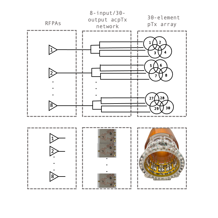
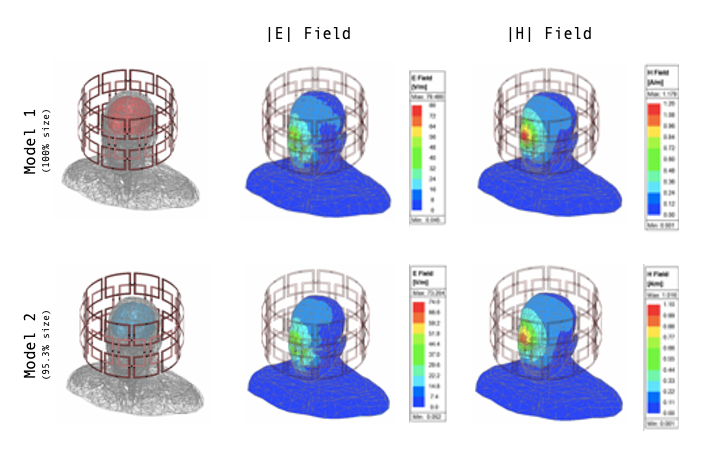
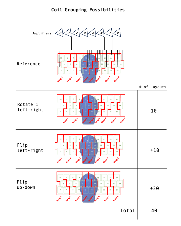
Fig 1. shows the overall transmit system along with the constructed 30-ch pTx coil and examples of the low-loss ratio adjustable power splitter PCBs that make up the optimized network. Given the previously built coil array, we know where each of the coil elements is situated. In simulation, we used 2 head models to calculate the E and H fields and global SAR matrices for the array. The resulting fields are shown in Fig 2. Given cabling constraints, we determined that each amplifier should drive a group of coils physically adjacent to one another. We began with a reference coil-to-channel grouping option and then shifted, flipped horizontally, and vertically to create 40 unique configuration options to exhaustively evaluate, as shown in Fig 3. For each of these 40 possible coil-to-channel configurations, we solved a magnitude least squares joint multislice shim problem that uses a rank constraint to enforce feasible compression weights that connect the channels and coil elements:\begin{array}{ll} \textrm{minimize}& \frac{1}{2} \sum_{i = 1}^{N_{sl}} \sum_{j = 1}^{N_{x}^i} \left| 1 - \left| \{ {S}_{i} {b}_{i} \}_j \right| \right|^2 + \frac{\lambda}{2} {b}_i {Q} {b}_i \\ \textrm{subject to} & \textrm{rank}({B}_k) = 1, \hspace{0.5cm} k=1, \dots, N_{ch}, \end{array}
Where, Si is an NxixNc matrix of complex-valued B1+ maps for each of the Nsl slices, and Nxi is the number of spatial locations. bi is a length Nc vector of shims. λ is a SAR regularization parameter and Q is an NcXNc global SAR matrix
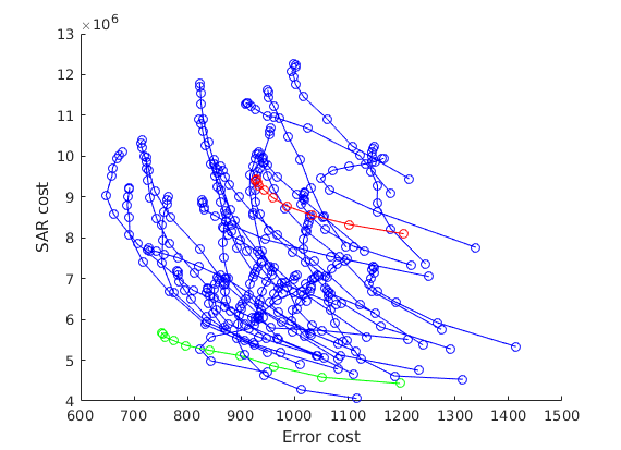
Importantly, this solution ensured that the shim for each coil element would be a scaled copy of the transmit channel shim. We used the l-curve method to compare the 40 configuration options by plotting the magnitude-squared error term against the SAR term, solving repeatedly across a range of l values to vary the SAR-homogeneity tradeoff. We also completed a range of shim designs using the identified optimal coil-to-channel mapping but setting the network weights to have equal uniform amplitude and CP-mode phase.
Results
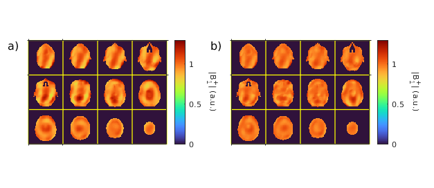
The l-curve results are shown for each of the 40 coil-to-channel mapping and the CP mode configuration in Fig 4. The different coil-to-channel mappings have very different l-curves, with one or two clear winning mappings; the mapping with a point closest to the origin (the green curve) was selected as the winner. The CP-mode mapping was among the worst five optimized mappings. Fig. 5 shows shimmed B1+ maps across axial slices in one of the models for both the CP-mode network with optimized shim weights and optimal network with optimized weights. The coefficient of variation (CoV) for the CP-mode network with optimized weights is 0.0802 with SAR cost of approximately 9.28e6 and the CoV for the optimal network with optimized weights is 0.0436 with a SAR cost of approximately 5.47e6.Discussion & Conclusion
We have described a framework to optimize a full acpTx transmit system given a fixed number of amplifiers, a set number of coil elements with cabling constraints, and a desired imaging application. The optimal network outperformed a CP-mode coil combination with optimized 8-channel shim weights by approximately 2-fold. This improvement in CoV, given the fixed number of configurations, shows the homogeneity in the field that can be gained by optimizing the network in comparison to a CP-mode network with an optimized set of weights, representing a more conventional 8-channel coil. A B1+ homogeneity improvement was seen in every slice. In future work, the optimized weights will be implemented for an imaging-based validation of the design.Acknowledgements
The authors thank Zhipeng Cao for previous work and thoughtful discussions. This work was supported by NIH grants R01 EB 016695, U01 EB 025162, 2T32 EB 001628-21, and R01 EB 031078.References
[1] Yan, X., Cao, Z., & Grissom, W. A. (2016). Experimental implementation of array‐compressed parallel transmission at 7 tesla. Magnetic resonance in medicine, 75(6), 2545-2552.[2] Cao, Z., Yan, X., & Grissom, W. A. (2016). Array‐compressed parallel transmit pulse design. MRM, 76(4), 1158-1169. [3] Cao, Z., Yan, X., Gore, J. C., & Grissom, W. A. (2020). Designing parallel transmit head coil arrays based on radiofrequency pulse performance. Magnetic resonance in medicine, 83(6), 2331-2342.[4] Grissom, W. A., Yan, X., & Cao, Z. (2019). Universal Coils: Multisubject Optimization of 8-Channel Many-Element Parallel Transmit Arrays. In Proc 27th Annual Meeting ISMRM, Montreal, QC, Canada.[5] Sappo, C. R., Drake, G., Yan, X., & Grissom, W. A. (2021). A 30-element transmit array for 7 Tesla brain imaging with array compressed parallel transmission. In Proc Annual Meeting ISMRM, Virtual (p. 1426).[6] Sappo, C. R., Gallego, G. L., Grissom, W. A., & Yan, X. (2022). On the design and manufacturing of miniaturized microstripline power splitters for driving multicoil transmit arrays with arbitrary ratios at 7 T. NMR in Biomedicine, 35(11), e4793.[7] Webb, A. G. (Ed.). (2016). Magnetic resonance technology: hardware and system component design. Royal Society of Chemistry.Figures