1407
Design of RF front-end circuit module for human 14T MRI system1Institute of Biomedical Engineering, Peking University Shenzhen Graduate School, Shenzhen, China, 2School of Electronics, Peking University, Beijing, China
Synopsis
Keywords: High-Field MRI, High-Field MRI, human 14T RF front-end
Motivation: The ultra-high field magnetic resonance imaging system can obtain ultra-high sensitivity and signal-to-noise ratio magnetic resonance imaging information, has become an important tool for basic research in brain science .
Goal(s): However, with the increase of field strength and operating frequency, the RF signal processing module, faces problems such as clutter interference, mirror frequency interference, which seriously affects the performance of the RF system and the final image quality.
Approach: We have solved these problems using methods such as secondary mixing.
Results: After key parameter testing and verification, it meets the application requirements of the human 14T ultra-high field magnetic resonance imaging system.
Impact: Our work has provided conditions for the construction of multi-channel RF modules in ultra-high fields, improving the quality of RF signal processing. Provided a hardware foundation for improving the quality of MRI images in ultra-high fields.
Introduction
The ultra-high field magnetic resonance imaging platform is mainly used for brain science and neurological disease research, which can provide more accurate brain functional imaging research and also enrich MRI imaging methods, enabling multiple atomic nucleus imaging1. However, with the increase of field strength and operating frequency, the difficulty of signal processing related to the RF module greatly increases. Problems such as mirror interference, clutter interference, and local oscillator frequency leakage can occur, seriously affecting the final imaging quality. We have developed a multi-channel RF front-end circuit module for human 14T ultra-high field magnetic resonance imaging system, which successfully solves the above problems and lays the foundation for the development of RF systems under 14T conditions.Method
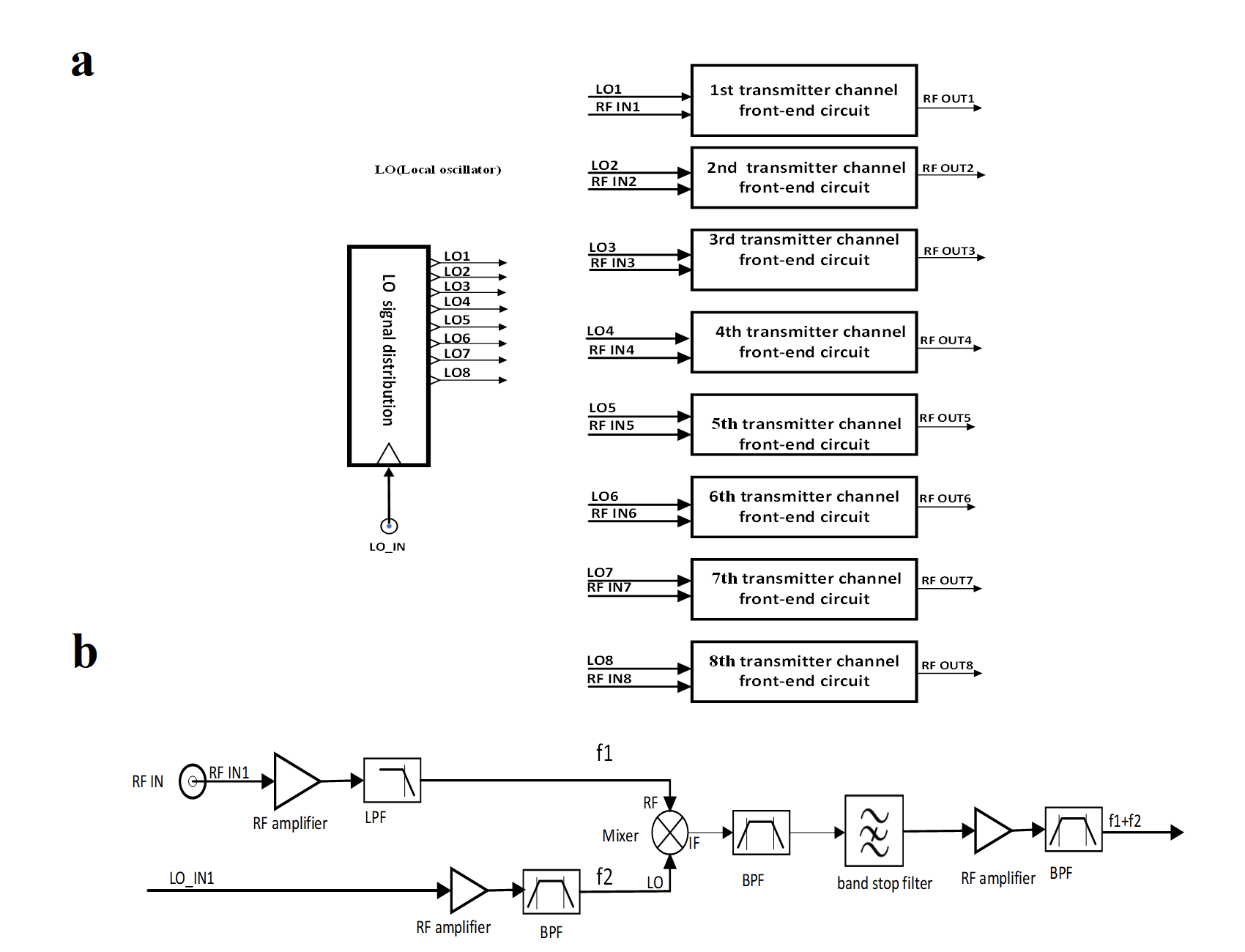
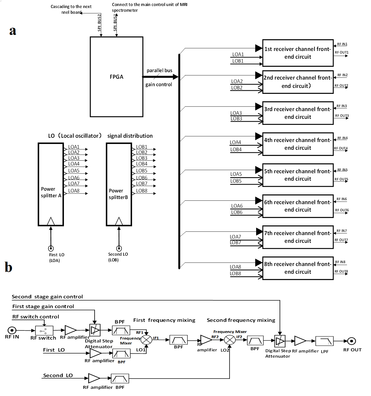
Fig1.(a) presents the transmitter module of the 14T RF system in the human body integrates an 8-channel transmitter front-end circuit , and an expansion port is reserved during design, simplifying the circuit configuration. With this way, multiple 8-channel board combinations can expand to more channels of transmitter modules. Fig1. (b) shows the multi-level filtering circuit design of the transmitter front-end module can effectively suppress interference caused by local oscillator leakage and clutter.The receiver module of the 14T RF system in the human body is equipped with an integrated board that integrates 8 channels of the receiver front-end circuit, as shown in Fig.2 (a). The board is designed with interconnection and expansion interfaces, which have good scalability. With an 8-channel board, it is easy to expand 16 channels, 32 channels, or even more channels. The mixing circuit structure adopts a secondary down mixing circuit. The first level down mixing outputs high and medium frequency values, while the second level down mixing outputs low and medium frequency values. Combined with a filter, it can effectively improve the circuit's ability to suppress mirror frequency interference signals. Reasonably allocate and adjust the gain of the amplification circuit, and allocate the gain control to two segments: high-frequency and intermediate frequency. The dynamic range of the gain control is large, and the control accuracy is high, as shown in Fig2. (b) .
Result
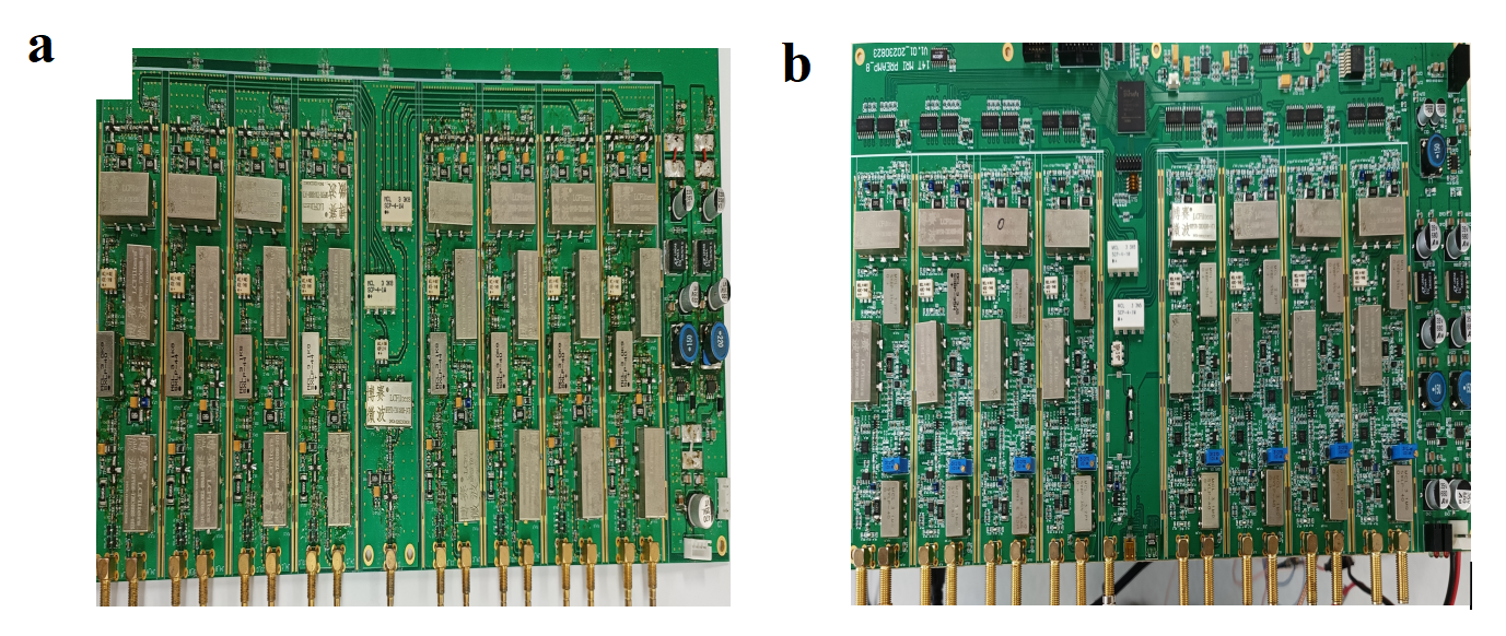
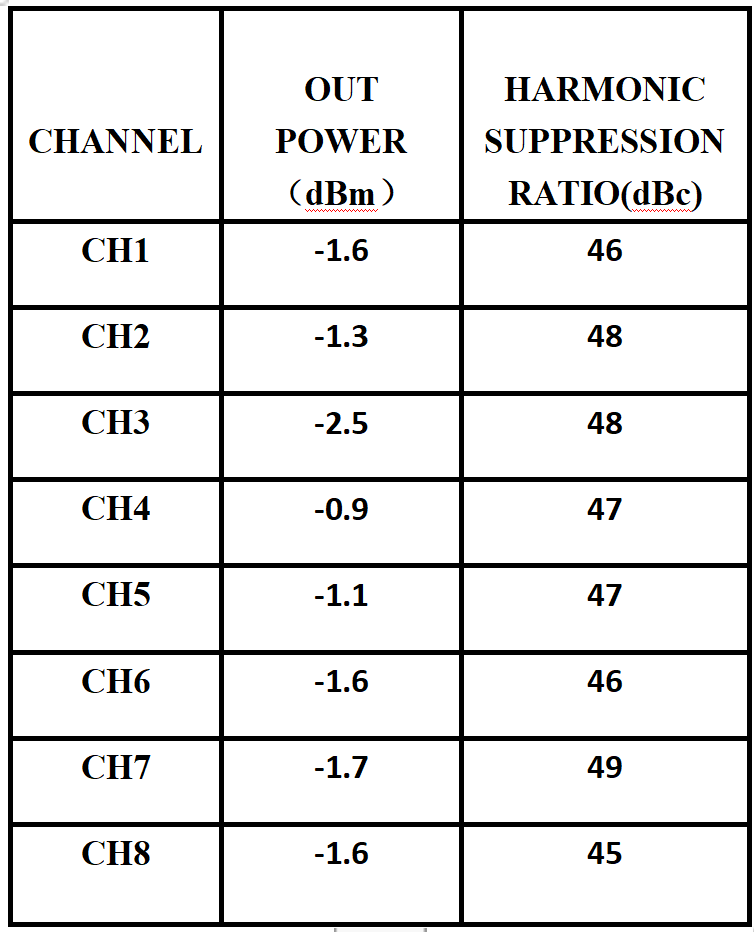
Fig.3 (a) shows the 8-channel RF transmitter front-end circuit module, and Fig.3 (b) shows the 8-channel receiver front-end circuit module.Table 1 presents the test results of key parameters such as output power and harmonic suppression ratio of the RF transmitter front-end circuit.The maximum harmonic suppression ratio is 49 dBc.It can be seen that the ability of the module to suppress harmonics meets the requirements.
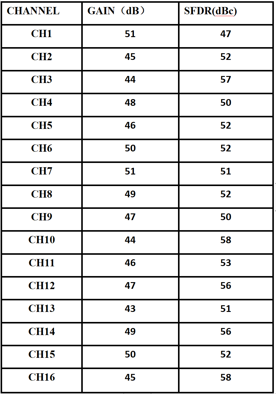
Key parameters such as RF receiver front-end circuit gain and spurious free dynamic range (SFDR) were listed in Table 2.The maximum SFDR value is 58 dBc. The data shows that the gain control ability and suppression performance of the module against stray noise meet the practical application requirements
Discussion
Our multi-channel RF front-end processing module for 14T applications not only measured parameters such as gain control, spurious free dynamic range (SDFR), and harmonic suppression ratio, but also used the imaging pulse sequence development and debugging software developed by the research group to test and verify the frequency, amplitude, and other parameters of the output waveform. The test results showed that the RF circuit module had excellent performance and reached the level of practical application.Conclusion
This work mainly solves some key issues in the ultra-high field RF signal processing module, laying the foundation for the subsequent development and practical application of multi-channel RF modules, RF shimming, and diversified RF coils in ultra-high fields.Acknowledgements
This work was supported by the Research on Key Technologies of Human 14T Ultra-high Field Magnetic Resonance Imaging System of the Development and Reform Commission of Shenzhen Municipality, China (Grant No. ZDKJ20190305002), National Natural Science Foundation of China (NSFC) under grant No.62271508References
1.Chu, S, Gras, V, Mauconduit, F, Massire, A, Boulant, N, Gunamony, S. Electromagnetic and RF pulse design simulation based optimization of an eight-channel loop array for 11.7T brain imaging. Magn Reson Med. 2023; 90: 770-783.Figures