1404
RF Shield design for transmit coils to reduce acoustic noise in MRI1Imaging Centre of Excellence, University of Glasgow, Glasgow, United Kingdom, 2MR CoilTech Limited, Glasgow, United Kingdom, 3NeuroSpin, CEA, Paris, France, 4Brain imaging center and Helen Wills Neuroscience institute, University of California, Berkeley, Berkeley, CA, United States, 5Advanced MRI Technologies, Sebastopol, CA, United States
Synopsis
Keywords: High-Field MRI, New Devices
Motivation: Eddy currents induced in the RF shield cause vibrations which generate acoustic noise.
Goal(s): To develop an RF shield that minimizes eddy currents and preserve the B1+ efficiency.
Approach: It was established that eddy-currents induced in the RF shield of the transmit coil are the primary source of acoustic noise in our 7T scanner. Therefore, the conventional slotted double layered RF shield was replaced by a segmented phosphor bronze mesh (PBM) to minimize eddy-currents and acoustic noise.
Results: Measurements performed at both ear locations of an anthropometric phantom demonstrate that the segmented PBM-based RF shield reduces the acoustic noise by up to 10dB.
Impact: Acoustic noise reduction could be achieved by using segmented PBM without compromising the transmit B1 field compared to the conventional double-layered slotted shield. Further improvements might be achieved with different mesh configurations besides the one implemented in this work.
Introduction
The 7T scanner at the University of California, Berkeley, is the first of the NexGen 7T scanners equipped with the investigational Impulse head gradient coil (Siemens Healthineers, Erlangen Germany) capable of achieving a maximum gradient strength of 200 mT/m and slew rate of 900 T/m/s per axis1. The changing magnetic flux from the time varying gradient magnetic field induces eddy currents on any conductive surface. This translates into resistive heat, vibrations and highly uncomfortable acoustic noise for the subject.Most transmit arrays used for brain imaging at 7T are locally shielded to minimise radiation loss and improve robustness of coil tuning inside the scanner bore. The RF shield is typically realised using a flexible double-layered PCB. Each layer is slotted to reduce eddy currents and the copper strips on the two layers are offset to form a high value capacitor, thereby the shield is continuous for RF. Heavily slotting the RF shield by minimising the strip width can minimise eddy currents but can also reduce shielding efficiency and thus be detrimental to the transmit B1 efficiency. Phosphor Bronze Mesh (PBM) has been used in the past to reduce gradient-induced eddy currents in RF shielding to protect electronics equipment in MRI2. This work presents PBM based RF shield for transmit coils to substantially reduce acoustic noise while simultaneously improving the transmit efficiency.
Methods
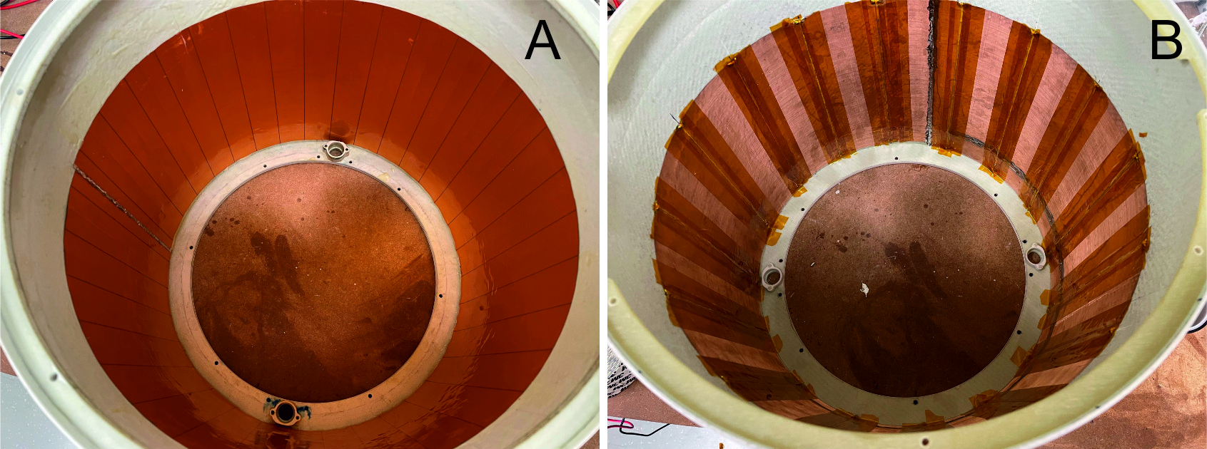
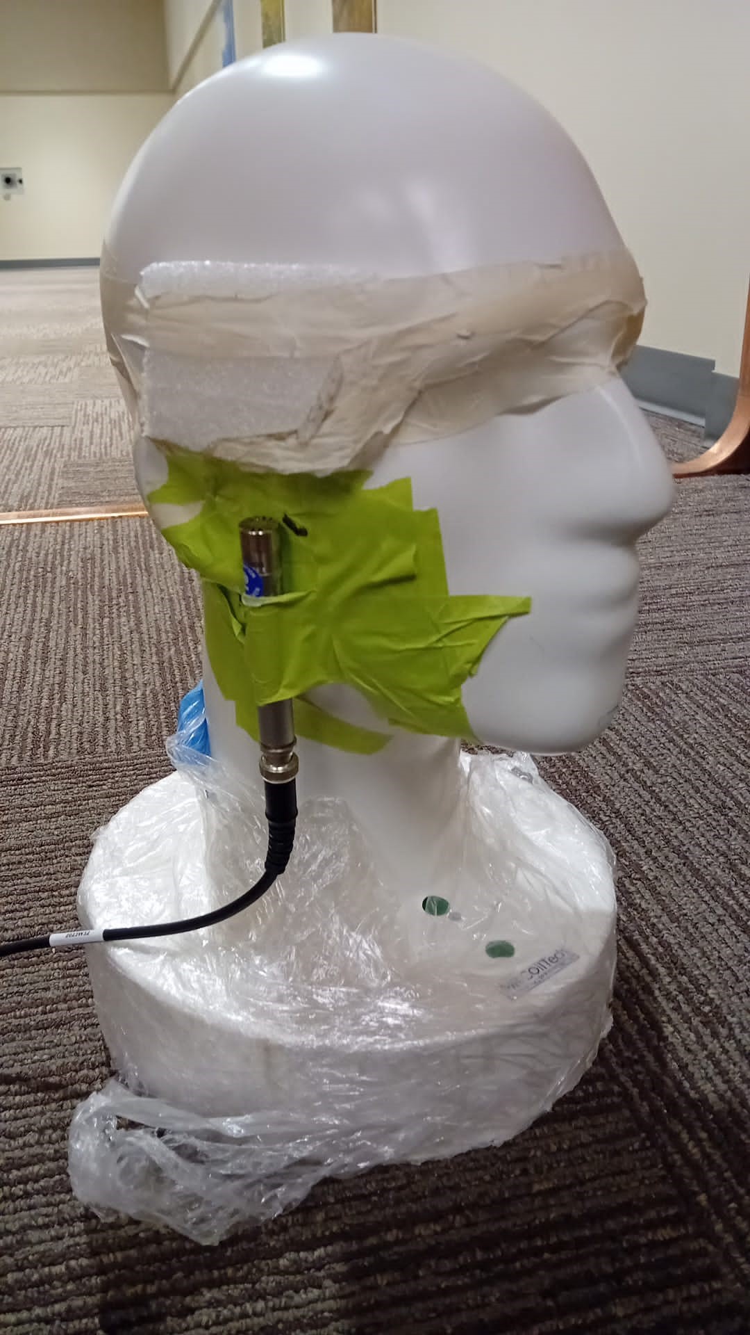
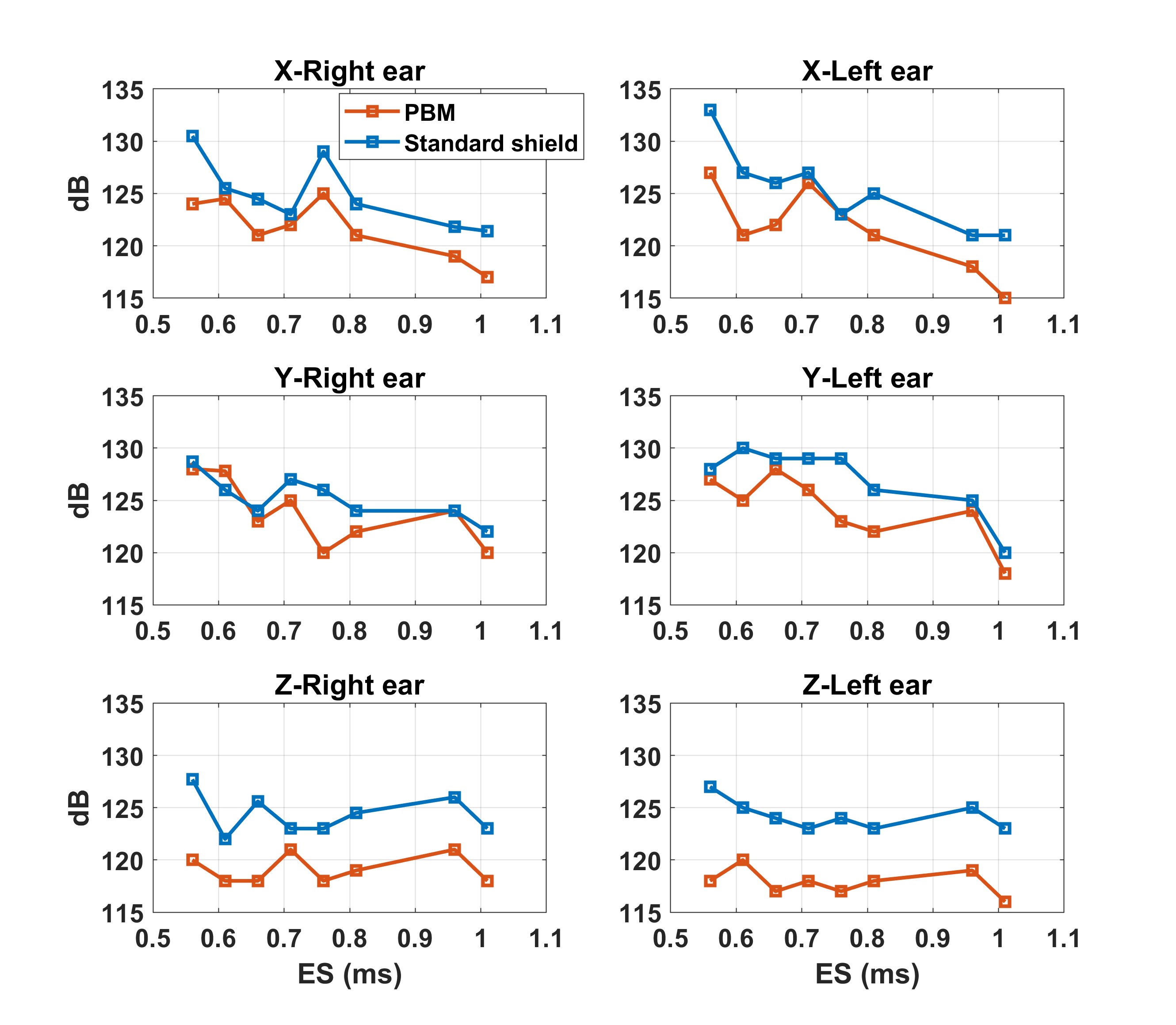
The study was performed on an 8-channel transmit 64-channel receive head coil1. The reference RF shield is a conventional two-layered design consisting of 34-longitudinal strips in each layer with a strip width is 32mm and copper thickness of 18um (figure 1A). Although not obvious at first, it was established through a series of experiments (submitted by N Boulant et al., ISMRM 2024)) that the primary source of acoustic noise beyond a cut-off frequency in the kHz range was caused by eddy currents induced in the RF shield and not by vibrations of the gradient coil. We used a PBM shield that consisted of 380 mesh count per inch (Shandong Xingying Technology, China) and segmented into 16 longitudinal strips with a 2mm gap. The adjacent strips were bridged together with 1000pF capacitors to make the shield continuous for RF (figure 1B).Sound pressure levels were measured using a dedicated sensor connected to a front-end and software (Bruël & Kjaer, Naerum, Denmark). To get a transfer function versus frequency, measurements were first performed with constant amplitude (G=2 mT/m) and linear frequency sweeps between 0 and 3.2 kHz in 2 min, for each gradient axis individually. Second, because the spectrum of MR sequences can be widespread, sound levels were also measured with EPI sequences at different echo spacings (0.56, 0.61, 0.66, 0.71, 0.76, 0.81, 0.96 and 1.01 ms) at constant gradient amplitude (76 mT/m), bandwidth and with the 3 readout axes (X, Y, Z) separately. The measurements were repeated at both ear locations of an anthropomorphic phantom (figure 2). To verify the change of the shield was not detrimental to the transmit efficiency, an Actual Flip angle Imaging (AFI) sequence was implemented to measure the B1+ field in CP mode.
Results
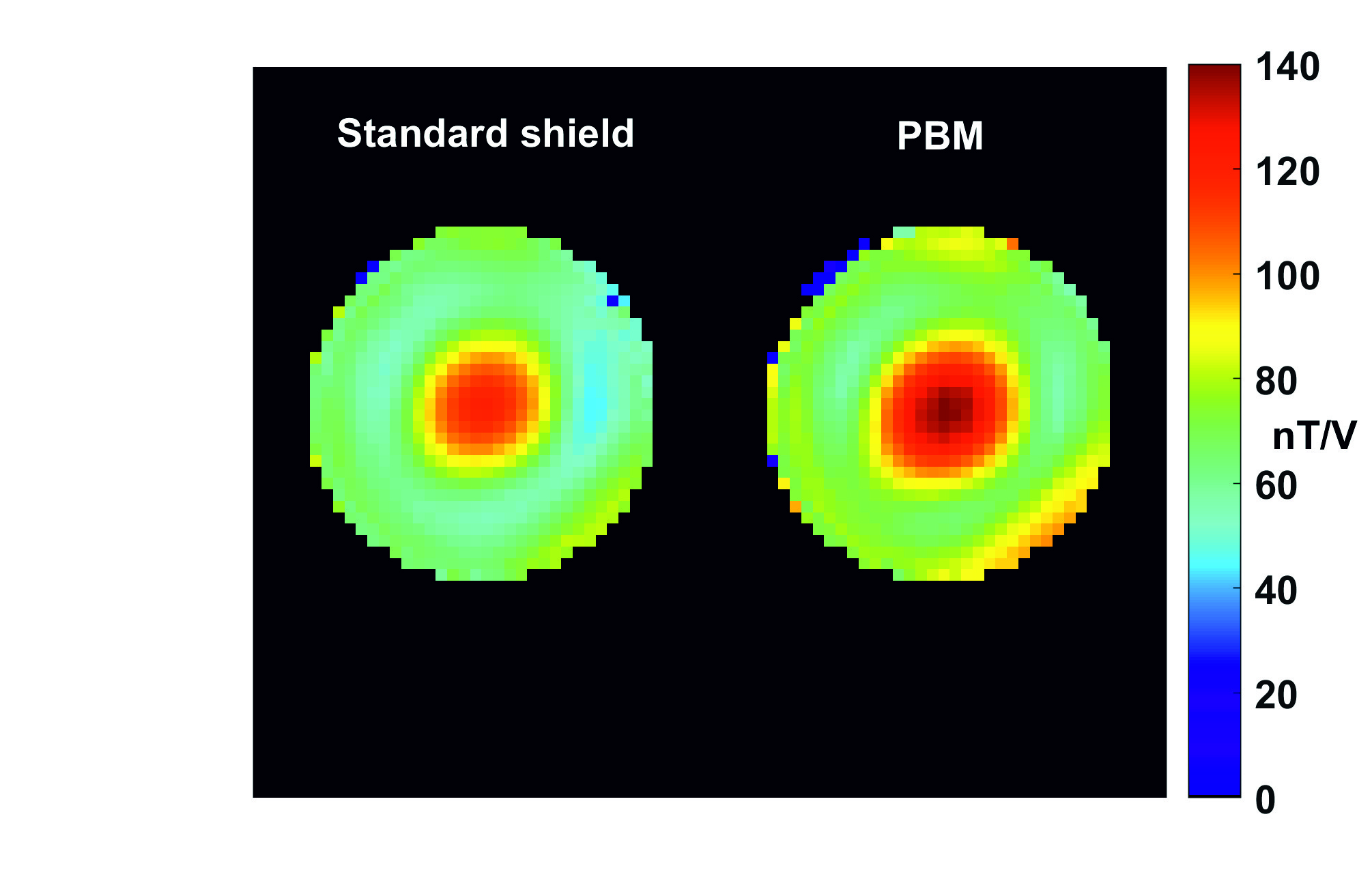
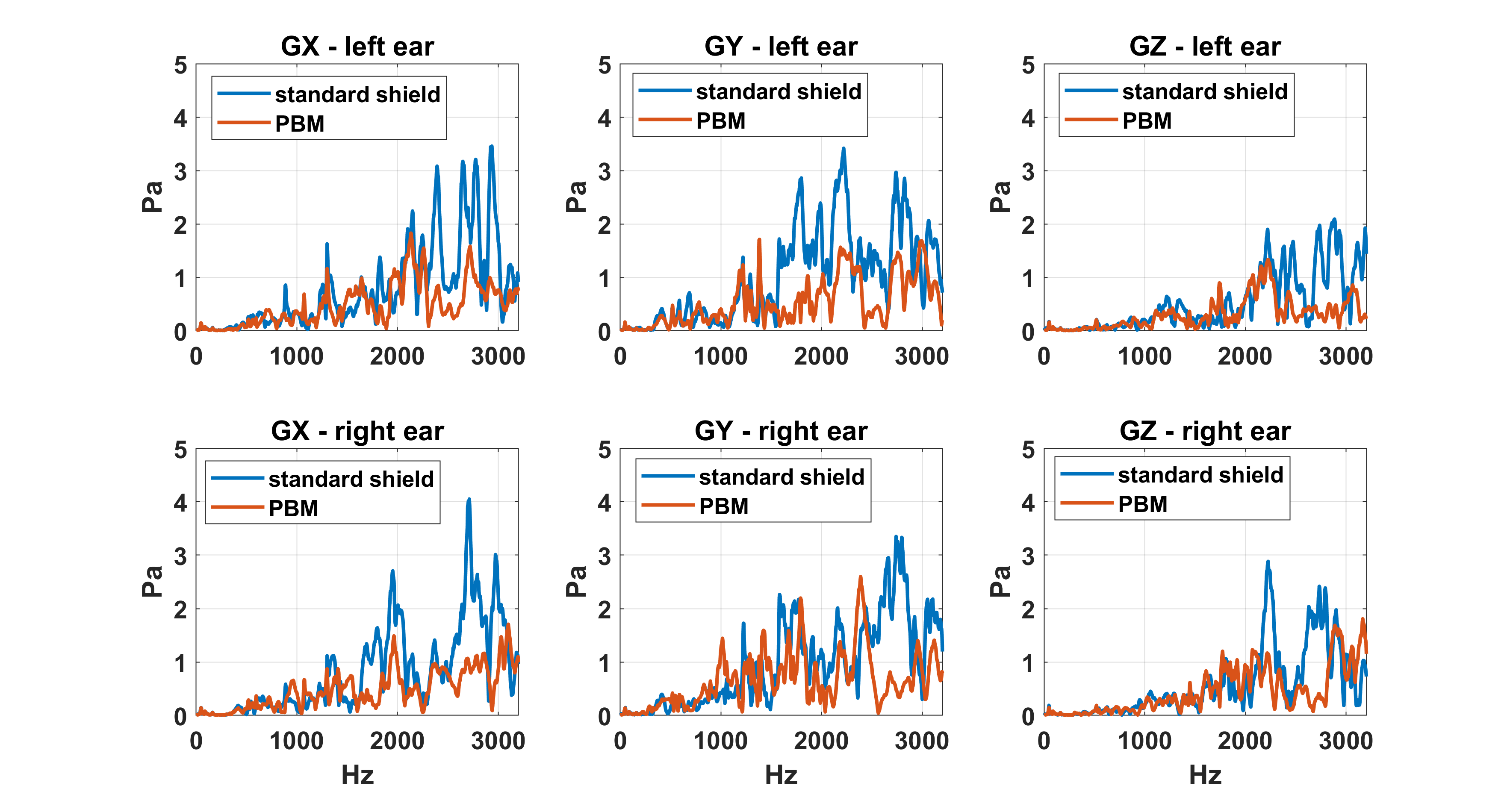
The B1 maps measured by driving the coil in CP mode, using the same reference voltage, are shown in figure 3. The wider strips of the PBM shield improved the overall transmit efficiency, yielding a gain in the center of about 15%. Figure 4 shows the acoustic transfer functions where a significant reduction of acoustic noise at high frequencies with the PBM shield was observed, consistent with eddy-currents being the primary cause of acoustic noise. Although the gain versus frequency is not systematic, the general trend is a drop of acoustic energy above 1.5 kHz, with some peaks even reduced sometimes by 10 dB. Figure 5 shows the sound pressure values acquired with EPI. Besides ES=0.61 ms where the PBM shield made it worse by 2 dB at the right ear and with the Y axis, the gains are systematic and vary between 0 and 9 dB.These results establish that current loops are disturbed and limited by segmenting and meshing the conductive surfaces, consequently minimising acoustic noise.Discussion and conclusion
We have demonstrated that acoustic noise reduction could be achieved by using PBM, without compromising the transmit B1 field. Now that eddy-currents in the RF shield have been identified as the main cause, at least in our system, this work paves the way for more improvements. We envisage creating smaller segments along the axial and longitudinal directions and overlapping the adjacent segments could further reduce the eddy currents and will be the subject of future work.Acknowledgements
The authors thank Dr Alex Becket (University of California, Berkeley) and Dr Samantha Ma (Siemens Healthineers, USA) for assisting us in fixing the RF shield and while collecting the data.
We acknowledge the following funding sources: AROMA H2020 FET-Open (885876). U01-EB025162, U24-NS129949, R44-MH129278 (NIH).
References
1. DA Feinberg et al., Nature Methods (Dec. 2023, in press)
2. Lee BJ et al., MRM 79 (2018)
Figures