1403
Impact of Matching Network Losses on RF Coil Q and SNR at Low Field Strengths.1Department of Radiology, NYU Grossman School of Medicine, Newyork, NY, United States, 2Center for Advanced Imaging Innovation and Research (CAI2R), Department of Radiology, NYU Grossman School of Medicine, New york, NY, United States
Synopsis
Keywords: Low-Field MRI, RF Arrays & Systems
Motivation: RF Coil design for low frequencies.
Goal(s): Demonstrate the impact of losses in different matching network topologies
Approach: we compared three- and four-element matching networks on 12 cm diameter coils at 10, 23.55, and 63.6 MHz. and evaluated coil loss and SNR.
Results: At 10 and 23.55MHz, the coils with three-element (single stage) matching networks exhibited approximately 50% lower unloaded Q compared to coils with four-element matching networks, whereas unloaded Q values were within 3% for three- and four-element matched coils at 63.6MHz. SNR at 23.55MHz (0.55T) was approximately 30% higher for the four-element matched coil over the three-element matched coil.
Impact: Resistive losses in four-element matching networks can be significantly lower than those of three-element networks at low frequencies or for lightly loaded coils, resulting in higher quality factor and SNR.
Introduction
In MRI, the sample and coil conductor loss and preamplifier noise figure are often considered to be the dominant sources of noise in the received signal. However, losses from receive coil matching networks, which transform the coil impedance to that required to minimize the preamplifier noise figure and to achieve pre-amplifier decoupling1, can also be significant.At low field strengths or in the case of lightly loaded coils (irrespective of the field strength) the resistive losses in matching networks can significantly degrade the Q and SNR2. This potential loss could be detrimental in low field MRI, where SNR is fundamentally low. In this work we compare two matching network designs and demonstrate the impact of their losses on coil Q and SNR.
Methods
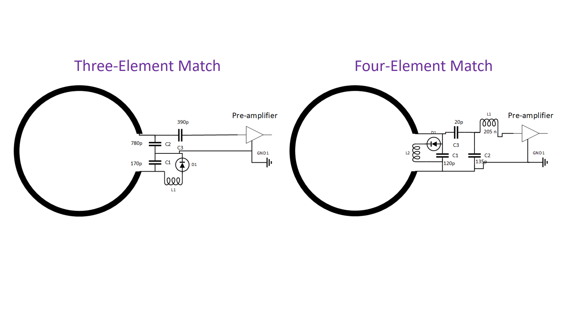
Coil design and evaluation: Identical circular loop coils with 12 cm diameter were constructed on copper clad PCB (39 mil thick, 1oz Copper). The coils were tuned and matched to 10, 23.55, and 63.6 MHz using either: an adaption of the three-element (single stage) match circuit1 or a four-element circuit3 (Fig. 1). The Q-values were measured using a vector network analyzer with the loops in free space and while loaded with a tissue-equivalent phantom. The Q-values were converted to SNR efficiency with respect to an ideal lossless coil using η ∝ √(1-QL ⁄ Q0 ) 4,5.Imaging: To quantify the SNR performance of the coils tuned to 23.55MHz, imaging experiments were performed on a 1.5 T MAGNETOM Aera (Siemens Healthcare, Erlangen, Germany) that was modified to operate as a prototype at 0.55 T as described by Campbell-Washburn et al6. The matching networks were set up to achieve preamplifier decoupling and included an active detuning network for isolation during RF excitation. Flip angle and SNR maps were respectively acquired using TurboFLASH (TE=1.9ms, TR=10000ms) and GRE sequences (with and without excitation). SNR maps normalized to sine of the excitation flip angle were computed for the two configurations.
Results
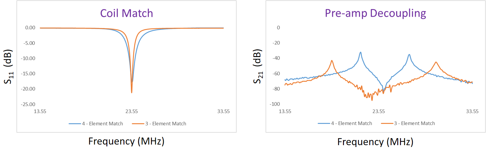
Table.1 shows that the four-element matching circuits resulted in about 50% unloaded Q and 10% efficiency improvement over the three-element matching circuits at 10 and 23.55MHz, whereas almost no differences in unloaded Q or efficiency were observed at 63.6MHz.The coils tuned to 23.55MHz were set up for MRI; Figure 2 shows that three- and four-element circuits provided suitable matching and preamplifier decoupling. The three-element match circuit featured a relatively large 780 pF capacitor that suggests high current through the network and potentially high loss with respect to the coil itself 3.
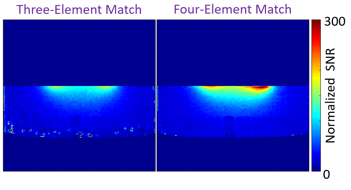
Experimental SNR maps that were normalized to the sine of the flip angle show that the loop with the four-element matching network had approximately 30% advantage over the three-element match (Figure 3).
Discussion and Conclusions
Here we present quantitative evaluations of how losses in matching networks affect coil performance. We show that coils incorporating lossy matching networks (where the capacitor value is high and effectively presents a low-impedance and pathway for high current) do incur a significant Q and SNR penalty at 10 and 23.55MHz, which further support the results of Wang et al and Reykowski et al 2, 3.Matching network losses are an important consideration in RF coil design. While straightforward three-element matching networks may be effective at clinical field strengths or when the loop size is large, in which case coil loss is dominated by the sample, four-element networks provide superior SNR when the sample loss is small (Table 1).
Acknowledgements
This work was performed under the rubric of the Center for Advanced Imaging Innovation and Research (CAI2R, www.cai2r.net), an NIBIB National Center for Biomedical Imaging and Bioengineering (NIH P41 EB017183).References
1. Roemer et al., Magn Reson Med. 1990 Nov;16(2):192-225
2. Wang et al., Proc. Intl. Soc. Mag. Reson. Med. 31 (2023), 3905.
3. Reykowski et al., Magn Reson Med. 1995 Jun;33(6):848-52.
4. Edelstein et al., Magn Reson Med. 1986 Aug;3(4):604-18.
5. Corea et al., Magn Reson Med. 2017 Aug;78(2):775-783.
6. Campbell-Washburn et al., Radiology. 2021 Feb 2: 204155.
Figures
|
|
|
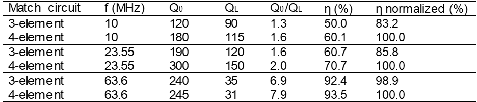
Table 1. Coil Q measurements and efficiency values. Unloaded Q and the (unloaded to loaded) Q ratio values clearly show that the three-element match accounts for significant losses at 10 and 23.55MHz but not 63.6MHz where sample loading is high. Efficiency values in the last column are normalized to those of the four-element match for each frequency.