1333
Implementation of an Optical System for Signal and Power Transmission in Light Coils1Division of Medical Physics, Department of Diagnostic and Interventional Radiology, University Medical Center Freiburg, Faculty of Medicine, University of Freiburg, Freiburg, Germany, 2Microsystems for Biomedical Imaging Laboratory, Department of Microsystems Engineering, University of Freiburg, Freiburg, Germany, 3Fraunhofer Institute for Solar Energy Systems ISE, Freiburg, Germany
Synopsis
Keywords: New Devices, New Devices, Optics
Motivation: RF-induced heating and reduced image signal-to-noise ratio (SNR) due to crosstalk between adjacent cables are problematic in dense receive arrays. RF coils with fiber-optical connection can overcome these problems associated with metallic wires.
Goal(s): To develop optical signal and power transmission units for MRI.
Approach: An analog photonic link with Mach-Zehnder modulator was constructed for optical signal transmission, and GaAs-based photonic power converters were used for power-over-fiber supply of low-noise-amplifiers (LNA).
Results: Image SNR and signal dynamic range of the photonic link are comparable with coaxial cable connection. Photonic power convertors can supply up to 10 LNAs in the receive chain.
Impact: Fully optical signal and power transmission is feasible for RF coils. It enables extremely dense modular receive arrays by eliminating cable-crosstalk and overcoming RF induced heating problems.
Introduction
With an increasing number of coil elements in a receive array also the crosstalk between the receiver cables and the risk for RF-induced heating increase. Cable traps or Baluns are commonly used to mitigate this problem1, but they can be bulky and inflexible, potentially complicating the coil design and increasing coil weight and size. Recently the Light Coils concept was proposed to completely eliminate RF heating and crosstalk problems2. In this study, we demonstrate the feasibility of optical signal and power transmission for Light Coils. For this, we use a Mach-Zehnder modulator (MZM) for MR-signal-to-optical-signal conversion3-7. To provide the electrical power for signal pre-amplification in the coil, we establish a power-over-fiber technology8 with photonic power converters (PPC)9,10.Methods
Optical Signal Transmission: An analog photonic link (Figure 1A) was constructed using a MZM (LN81S-FC, Thorlabs, USA). The operating point was set by adjusting the DC bias voltage. At the optimal bias voltage, MZM is operated within its linear regime and maximizes the optical signal amplitude. The photonic link was implemented into the receive chain of a 3T clinical MRI scanner (MAGNETOM Prisma, Siemens, Germany) (Figure 2). The link was tested in a phantom measurement using a surface coil and 2D FLASH sequence (TR/TE=60/4 ms, α=20°, FOV=192×192 mm2, BW=320 Hz/pixel). In addition, in vivo measurements of the human eye and wrist were performed with T1w-FLASH (TR/TE=300/2.5 ms, α=70°, FOV=192×192 mm2, BW=425 Hz/pixel) and TSE (TR/TE=2500/33 ms, α=150°, FOV=119×119 mm2, BW=200 Hz/pixel) sequences, respectively. For comparison, measurements were repeated with a conventional coaxial cable connection. Dynamic range (DR) of the photonic link was optimized using variable gain stage between the receive coil and the input of the MZM, covering 10-50 dB gain in 5 dB step.Optical Power Transmission: Single-junction GaAs-based PPC11 and 1W laser (RLTMDL-852-1W, Roithner Lasertechnik, Austria) with an operating wavelength of 852 nm were used for power transmission. PPC chips (Ø=1 mm²) were mounted on TO-46 sockets, but no dedicated heat sink was integrated. To ensure that the entire beam spot hits the active area of the PPC, custom-made fiber-to-PPC couplers were connected between fiber end and TO socket (Figure 3A). To supply sufficient voltage of 4-5 V for the LNA, 4 PPCs were connected in series and 3 fiber splitters were used to distribute laser power to PPCs (Figure 3B). The open-circuit voltage and short-circuit current were measured, and the overall power conversion efficiency was calculated.
Results
Operating curve of the MZM (Figure 1B) shows that at a bias voltage of 2.55V the MZM has the maximum sensitivity, which leads to the highest output signal amplitude (Figure 1C). Thus, in all subsequent measurements this bias voltage was used. Figure 4A compares the phantom images acquired via the proposed photonic link and conventional coaxial cable. With increasing gain the image SNR increases up to a maximum of SNR=278 at 40 dB (Figure 4B). From the highest signal at k-space center and the minimum detectable signal (noise), the signal dynamic range (DR) was calculated (Figure 4C). DR of the coaxial cable connection and the photonic link are 75 dB and 82 dB respectively. The results of in vivo measurements and SNR maps are shown in Figure 5. Regarding the power transmission, the output of 4 PPCs in series was stable in a 5-minute timeframe. The open-circuit voltage of the series was 4.7±0.05 V and the short-circuit current was 60±4 mA. The output power of the 4-PPC series was around 280±20 mW. Compared with the output power of the fiber, the overall conversion efficiency of the PPCs with couplers is 48±5 %.Discussion
We demonstrated that the performance of optical signal transmission was comparable to a conventional coaxial cable, the image SNR is only 6% less. Gain stage before the MZM input is crucial to match the SNR and DR. Higher gains suppress noise of the entire cascade link (Friis formula12). Increasing input laser power and photodiode responsivity might further improve the performance.In optical power transmission, high efficiency coupler is advantageous. The voltage and current requirements of the LNAs determine the number of PPCs needed. Using multi-junction photovoltaic cells13,14 will minimize the space requirements and increase efficiency. Lower power consumption LNAs are currently under development to minimize power requirements.
Acknowledgements
No acknowledgement found.References
- Peterson, David M., et al. "Common mode signal rejection methods for MRI: Reduction of cable shield currents for high static magnetic field systems." Concepts in Magnetic Resonance Part B: Magnetic Resonance Engineering: An Educational Journal 19.1 (2003): 1-8.
- Özen, Ali Caglar, et al. "Light coils: MRI with modular RF coils using optical power and data transmission." Proceedings of the 30th Annual Meeting of ISMRM, United Kingdom. 2022.
- Yuan, Jing, Juan Wei, and Gary X. Shen. "A direct modulated optical link for MRI RF receive coil interconnection." Journal of Magnetic Resonance 189.1 (2007): 130-138.
- Memis, Omer Gokalp, et al. "Miniaturized fiber‐optic transmission system for MRI signals." Magnetic Resonance in Medicine: An Official Journal of the International Society for Magnetic Resonance in Medicine 59.1 (2008): 165-173.
- Yuan, Jing, Juan Wei, and Gary X. Shen. "A 4-channel coil array interconnection by analog direct modulation optical link for 1.5-T MRI." IEEE transactions on medical imaging 27.10 (2008): 1432-1438.
- Koste, Glen, et al. "Magnetic resonance imaging, a commercial application for analog photonics." IEEE Conference Avionics Fiber-Optics and Photonics, 2005.. IEEE, 2005.
- Nobre, Paul, et al. "Optical link as an alternative for MRI receive coils: toward a passive approach." IEEE Transactions on Biomedical Engineering (2022).
- Matsuura, Motoharu, et al. "150-W power-over-fiber using double-clad fibers." Journal of Lightwave Technology 38.2 (2019): 401-408.
- Algora, Carlos, et al. "Beaming power: Photovoltaic laser power converters for power-by-light." Joule 6.2 (2022): 340-368.
- Helmers, Henning, et al. "68.9% efficient GaAs‐based photonic power conversion enabled by photon recycling and optical resonance." physica status solidi (RRL)–Rapid Research Letters 15.7 (2021): 2100113.
- Höhn, O., et al. "Optimal laser wavelength for efficient laser power converter operation over temperature." Applied Physics Letters 108.24 (2016).
- Friis, Harald T. "Noise figures of radio receivers." Proceedings of the IRE 32.7 (1944): 419-422.
- Schubert, J., et al. "High-voltage GaAs photovoltaic laser power converters." IEEE Transactions on Electron Devices 56.2 (2009): 170-175.
- Fafard, Simon, et al. "Ultrahigh efficiencies in vertical epitaxial heterostructure architectures." Applied Physics Letters 108.7 (2016).
Figures
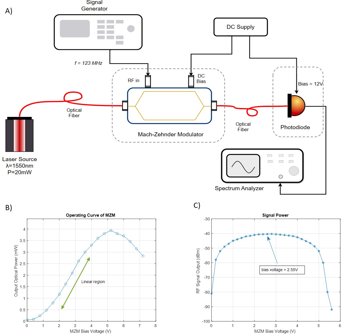
Figure 1: A) Setup of analog photonic link with external modulation architecture. The input RF signal of the MZM was generated by a signal generator, which is set to fLarmor (3T) = 123 MHz. A DC power supply is used to bias both the MZM and the photodiode. The output RF signal of the photodiode was then sent to a spectrum analyzer to observe its amplitude. B) Operating curve of the MZM. The green arrow shows the linear region of the curve. C) Output signal amplitude on the spectrum analyzer with varying DC bias, when the bias is 2.55V the amplitude reaches the maximum value.
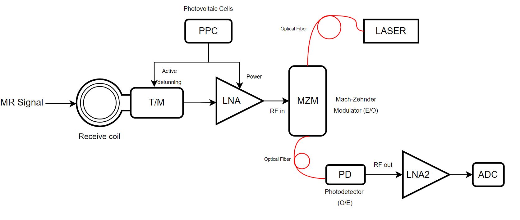
Figure 2: Schematic overview of the optical signal and power transmission line. The received signal is sent to the MZM after optically detuned circuit and powered LNA. After electrical-optical conversion by the MZM and optical-to-electrical conversion by the photodiode, the output signal is digitized by an ADC. The LNA interface between the MZM and the T/M circuit contains 2 LNAs and 3 attenuators, the power gain can vary from 10 to 50 dB with 5 dB step.
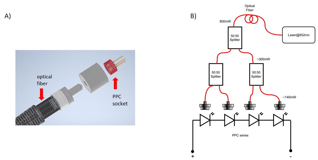
Figure 3: A) 3D model of fiber to PPC coupler. B) Optical power transmission line. The optical power delivered to the first splitter is 800mW. The measured power for each output fiber after splitting is 300mW. Finally, 145mW optical power is sent to each PPC coupler.
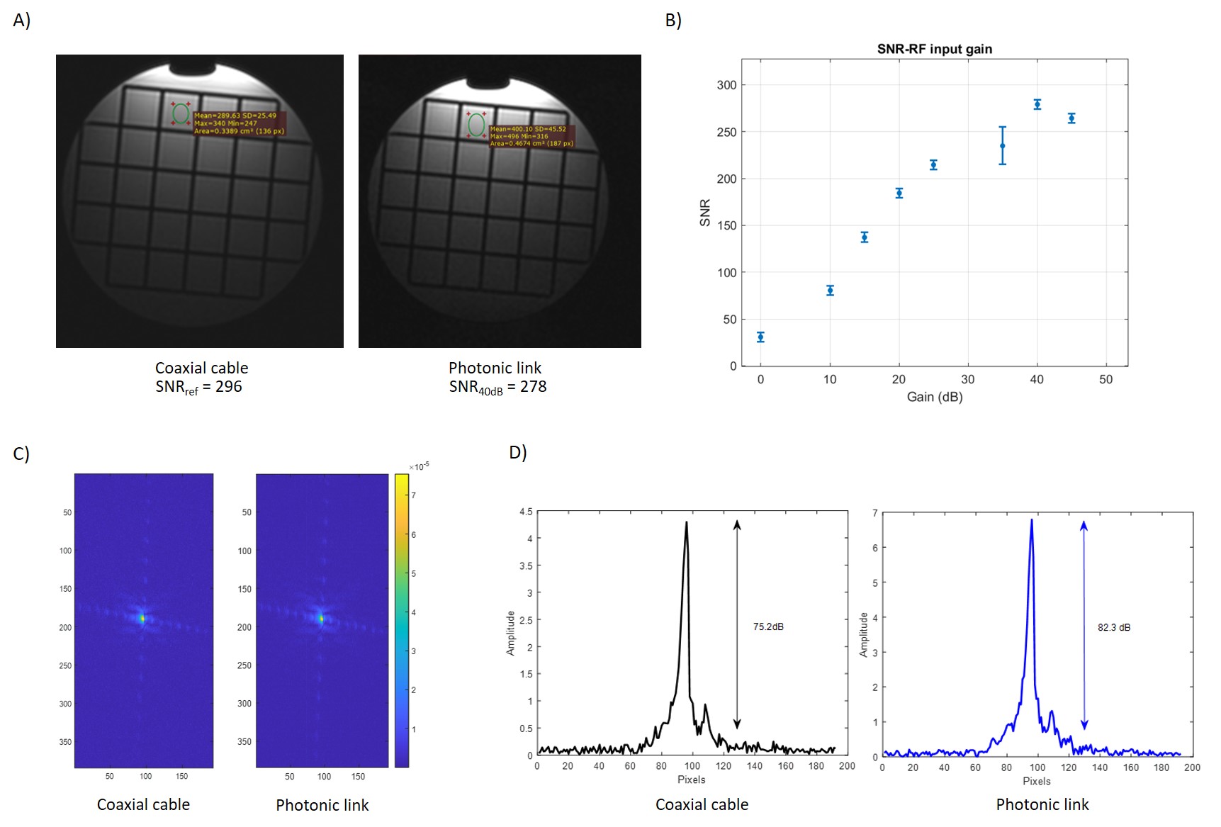
Figure 4: A) Phantom images acquired with coaxial cable connection and photonic link with 40 dB gain. B) Image SNR with varying gain. The SNR increased with gain and reached its maximum value of 278 at a gain of 40 dB. C) k-space of coaxial cable connection and photonic link with 40 dB gain. D) Dynamic range extracted from a horizontal line passing through the center of corresponding k-space.
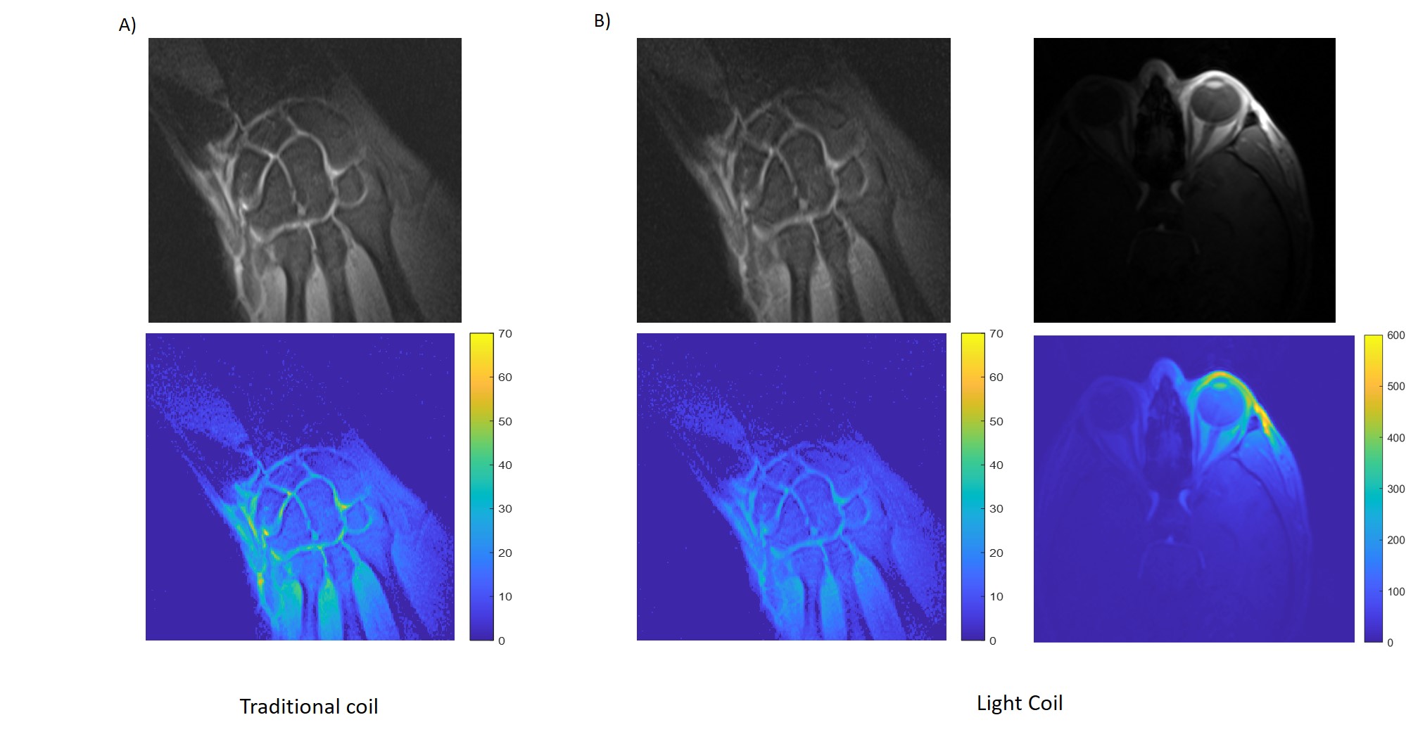
Figure 5 : In vivo measurements and SNR maps. A) Wrist imaging with traditional coaxial cable connection. B) Wrist and eye imaging with photonic link at 40 dB gain.