1329
A 16-channel MR-PET array coil for high-resolution parallel transmit brain imaging at 7T1Radiology, A.A.Martinos Center of Biomedical Imaging/Massachusetts General Hospital, Charlestown, MA, United States, 2Harvard Medical School, Boston, MA, United States, 3Department of Physics, Massachusetts Institute of Technology, Cambridge, MA, United States, 4Harvard-MIT Division of Health Sciences Technology, Cambridge, MA, United States
Synopsis
Keywords: PET/MR, Parallel Imaging, MR-PET 7T array
Motivation: We are developing the Human Dynamic NeuroChemical Connectome, a high spatio-temporal resolution brain PET (HSTR-BrainPET) scanner integrated with a 7T MR system
Goal(s): To build a 16-channel PET-compatible RF coil with parallel transmit capability based on an 8-channel test array for high-resolution imaging.
Approach: We designed and built multi-channel transmit-receive coils with RF screen that fits inside the spherical geometry of the PET camera. Coil performance was characterized with and without PET modules present.
Results: The performance of the 8-channel coil was satisfactory. Preliminary tests with the 16-channel array showed some loss in sensitivity in the CP mode.
Impact: By designing a 16-channel transmit-receive RF head coil and RF screen that both conform to the novel spherical geometry PET camera, we can acquire high-quality MR data simultaneously with PET data while also minimizing 511 keV photon attenuation.
Introduction
We are developing a high spatio-temporal resolution brain PET (HSTR-BrainPET) scanner integrated with a 7T MR system. Our primary goal is to build a PET camera with an order of magnitude higher sensitivity than existing MR-compatible PET devices to allow investigators to seamlessly merge the dynamic functional capabilities of PET and functional MRI on a comparable time scale [1]. Given the limited space and the need to minimize 511 keV photon attenuation, we designed and built an 8 and a 16-channel transmit-receive radio-frequency (RF) brain coil and RF screen that conforms to the unique spherical design of the PET detectors. The coil helmet is contoured for comfort with eye cutouts to accommodate video goggles. It is connected to 16 individual transmit receive switches with preamplifiers. SNR and B1+ of the CP mode were evaluated for the two arrays.Methods
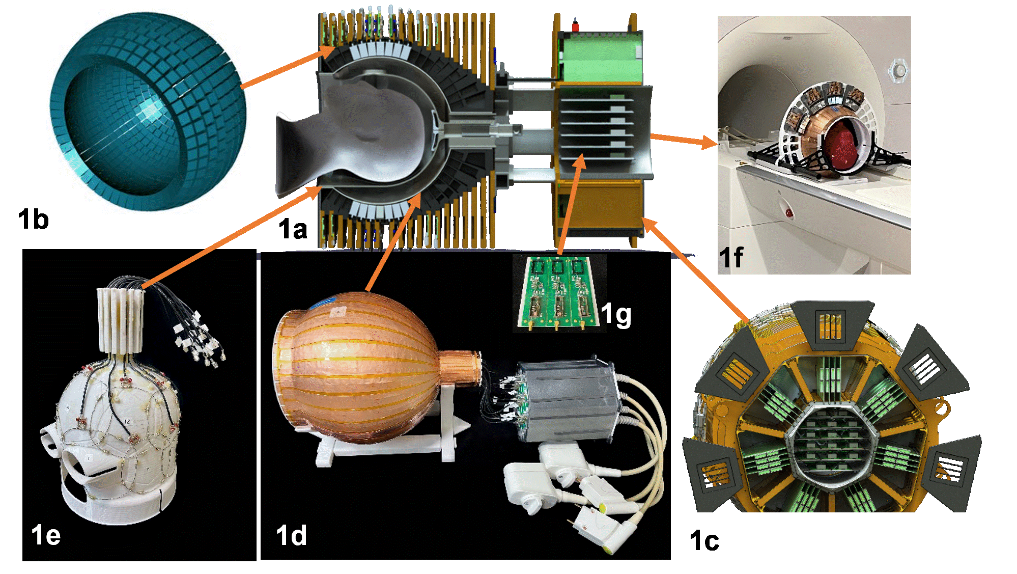
Fig.1a shows the main components of the spherical Brain-PET insert (Fig. 1b) arranged around a partial sphere (32 cm inner Ø, with a 25 cm Ø front opening to allow the positioning of the subject and a 9 cm Ø back opening) [2]. PET detection efficiency is enhanced using 26 mm long LSO crystals and high-performance readout electronics with DOI and TOF capabilities (Fig.1c). Figure 1d shows the helmet former with RF shield along with an interface box housing TR switches and preamps (Fig. 1g). The helmet (Fig. 1e) was sized to accommodate most adult heads and 3D printed. Coil elements are arranged in an overlapped array with two rows of eight elements each (16ch array) or a single row (8ch array). AWG18 wire loops with six equally spaced capacitors was used to improve the unloaded-to-loaded Q and to minimize attenuation by the PET camera. To eliminate cable current losses and have a balanced feed at the coil we used 1:1 180º lumped element balun [3]. In addition, cable traps were placed in front of the T/R switches/preamps in the interface unit positioned outside the PET FOV. The design of the copper-clad Kapton (polyamide) slotted shield consists of two layers of overlapping conductive patches (PyraluxAC182500RY), with a thin layer of Kapton dielectric between the patches to provide the necessary distributed capacitance to complete the RF current paths at 300MHz while breaking eddy currents. Data were acquired on an FDA-approved 7T MRI scanner (MAGNETOM Terra, Siemens Healthcare), (Fig. 1f) using an oil phantom to acquire B1+ maps (64x64 matrix, FOV 192x192mm, slice thickness 10mm) to determine the correct magnitude and phase for CP mode. SNR maps were obtained following the method of Kellman & McVeigh [4] using the same oil phantom. Noise covariance was estimated from thermal noise data using an anthropomorphic head phantom [5] and 3D ME MPRAGE (acceleration 2, FOV 256x256x192mm, Resolution 1mm isotropic, TR 2.5s, ∆TE 1.86ms, 4 echoes, TI 1s, Flip angle 8 ⁰, bandwidth 650Hz/pixel) was acquired. The 8-channel test array was used along with a single ring of the PET with 12 modules to compare B1+, B0, eddy current field compensation with and without the presence of the PET gantry.Results
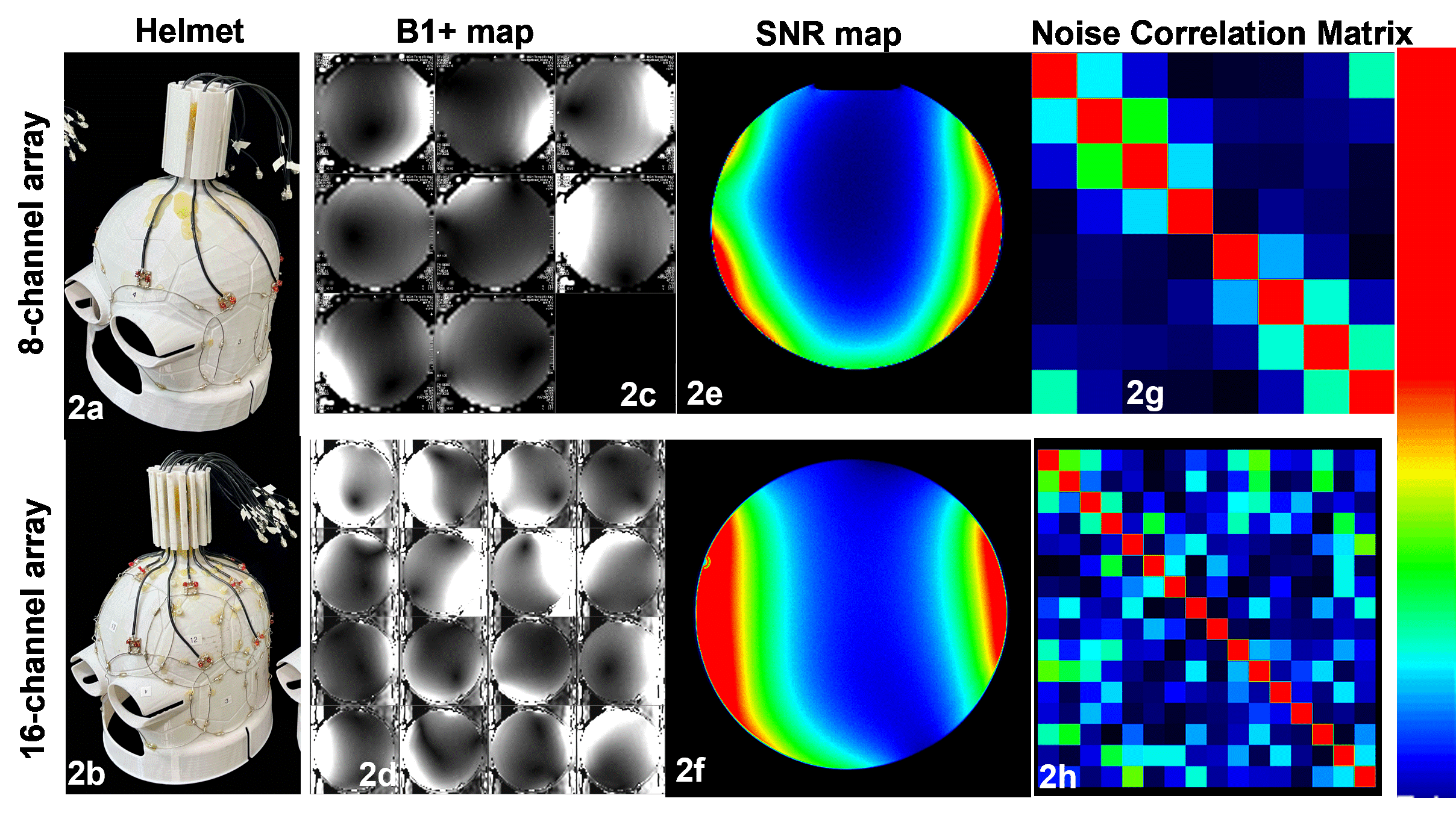
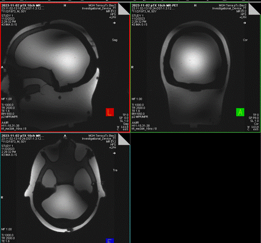
Bench tests on each coil element showed a Q unloaded-to-loaded ratio of ~130/110. S21, between loaded neighboring elements and the next neighboring elements ranged from -18 dB to -11.5 dB. S11 reflections showed the elements tuned and matched to 50 Ω. Fig. 2a, 2b shows the two 3D printed arrays with similar designs. Fig. 2c, 2d show the corrected and uncoupled individual magnitudes for the 8 and 16 elements of the two arrays to compute the CP mode. Fig. 2e, 2f shows the average SNR 29.33 and 35.35 from the two arrays. Fig. 2g, 2h shows the noise correlation matrix between channels for an average of 17.3% and 21% for the two arrays. Fig. 3 shows a 3D ME MPRAGE. The same maps were acquired again with a single PET ring and 12 modules turned on with the 8-channel test array, which showed that there was minimal drop in the SNR and the B1+ map and had minimal effect on static B0 field, B1+ field, and on the eddy current field.Discussions and Conclusion
A 16-channel transmit MR-PET array was successfully built and tested. It shows some loss in sensitivity in CP mode due to the presence of cable currents and interactions with 16 cables near each other, compared to an 8 -channel test array where cable arrangement is further apart, while RF performance was optimized with no cable interactions, a point to be addressed and solved.Acknowledgements
This work was supported, in part, by BRAIN Initiative NIH-NIBIB & NINDS grant 1U01EB029826-01.References
[1] Sander et al. MRM 2015 73(6), [2] Scipioni et al. IEEE NSS 2023, [3] Rivera et al. (2011) Proc ISMRM, [4] Kellman et al. MRM 2005, 54(6): 1439-47, [5] Graedel et al. (2014) MRMFigures