1319
Modular Dynamic Torso Motion Phantom for MRI1High Field MR Center, Center for Medical Physics and Biomedical Engineering, Medical University of Vienna, Vienna, Austria, 2Center for Medical Physics and Biomedical Engineering, Medical University of Vienna, Vienna, Austria, 3QIMP Team, Center for Medical Physics and Biomedical Engineering, Medical University of Vienna, Vienna, Austria
Synopsis
Keywords: Phantoms, Phantoms, Motion
Motivation: The development of motion tracking and correction methods requires suitable motion phantoms.
Goal(s): The design, fabrication, assembly and testing of a modular dynamic torso phantom.
Approach: The phantom consists of a saline-filled acrylic shell, with dimensions comparable to a human torso and three distinct interior motion modules. Two linear piezo stages are used to mimic breathing motion of the chest wall and the abdominal organs including the heart, respectively. A pneumatic system is used to move a heart mock-up to represent cardiac motion.
Results: The motion capabilities and MR compatibility of the phantom are validated in 3 T MRI experiments.
Impact: This work presents the development of a dynamic torso phantom for MR applications, i.e. a scientific instrument that can serve as ground truth for the investigation and characterization of novel motion compensation and tracking methods.
Motivation
For magnetic resonance imaging (MRI) of the torso, motion presents a challenge due to inevitable respiratory and cardiac motion. Depending on the image acquisition technique, motion can cause artifacts, including blurring, ghosting, signal dropouts and unwanted signal enhancement1. Therefore, motion tracking and compensation are subject of past and ongoing research2. The development of such techniques requires suitable phantoms that provide user-defined motion models with sufficient spatial/temporal accuracy and reproducibility. Therefore, this work targets the development of a dynamic torso motion phantom that can serve as ground truth for the investigation and characterization of motion compensation and tracking methods.Methods
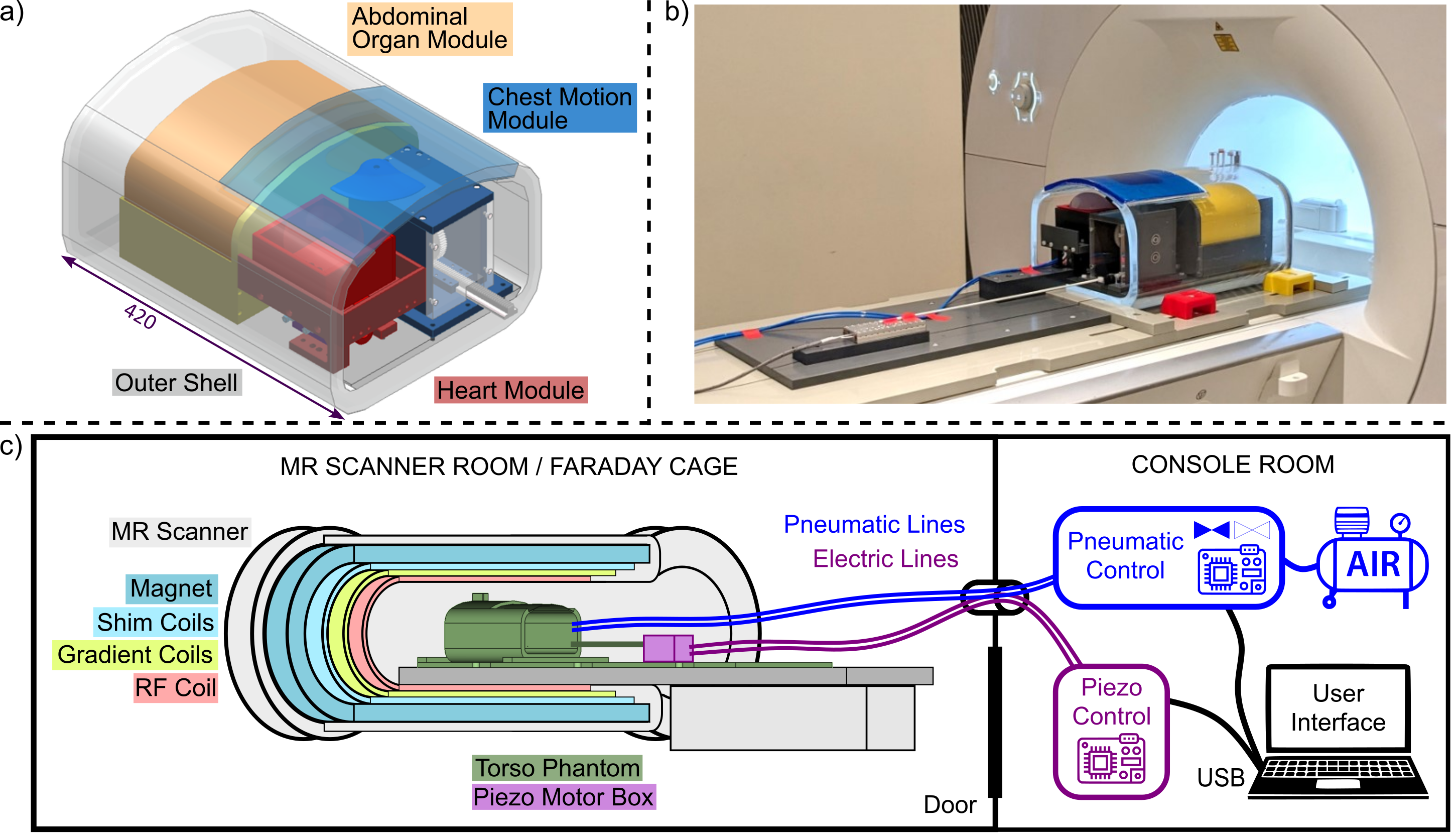
Figure 1 shows the dynamic torso phantom with its motion modules featuring three degrees of freedom (DOFs): (1) breathing motion of the chest wall predominately in anteroposterior direction (20 mm max. amplitude, 0.5 Hz max. rate), (2) breathing motion of the heart and the abdominal organs in craniocaudal direction (50 mm max. amplitude, 0.5 Hz max. rate), (3) simplified cardiac motion in craniocaudal direction (20 mm amplitude, 4 Hz max. rate). The phantom position in the scanner corresponds to feet-first supine.The motion modules are enclosed in a double-walled acrylic shell (fabricated by Acrylstudio GmbH, Austria) filled with saline solution (approx. 5 L deionized water, 5 g/L NaCl, 1 ml/L Gadoteriol contrast agent) . The top front part of the shell is not covered by acrylic glass but by a low-cost commercially available flexible gel mat (290 x 290 x 10 mm, polyurethane) representing the moveable chest wall. Breathing motion (DOF 1 & 2) is realized with two independently controlled non-magnetic linear piezo stages (Xeryon, Belgium) with a nominal driving force of 3 N, maximum travel rage of 109 mm, speeds of up to 200 mm/s and spatial accuracy in the µm range featuring customizable movement patterns.
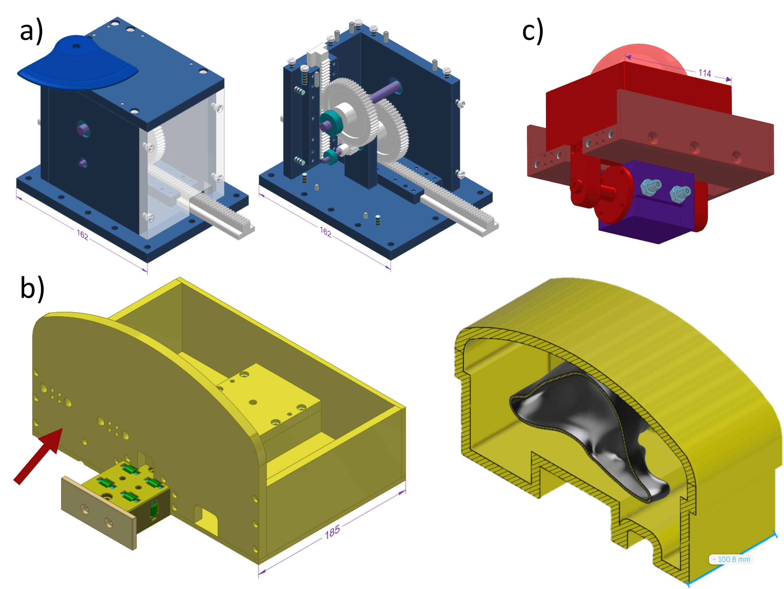
For chest motion (DOF 1), the horizontal movement of the piezo stage is translated into a vertical movement via a gear box (Fig. 2a) containing a compound gear with a ratio of 1:5, providing an increase of the driving force. This gear box holds a push head that contacts and lifts the gel mat.
For abdominal organ motion (DOF 2), a monorail track and a bulk shell on a wagon were constructed (Fig. 2b). In the bulk shell, different organ phantoms can be placed (e.g., the additively manufactured liver mock-up with main vessels shown in Fig. 2b). The heart module is attached to the abdominal organ wagon to emulate heart movement with the breathing cycle. Preliminary tests revealed that the piezo driving force also needs to be increased for abdominal organ motion. Therefore, a second gear box placed between the piezo motor box and the phantom body is currently under construction.
To mimic heartbeat motion (DOF 3), a sliding box holding a heart phantom (i.e., SLA-printed heart segmented from an MRI scan filled with gel3: 250 g deionized water, 250 g ethylene glycol, 3.5 g NaCl, 5 g Agarose, 0.25 g Sodium azide, and 1.5 ml Gadoteridol contrast agent), and a full-plastic pneumatic movement system connected underneath were designed (Fig. 2c). A double-action piston is used to avoid the need for a metal spring for retraction. The pneumatic system is supplied with compressed air (1.5 bar) from outside the scanner room via electromagnetic valves (Festo GmbH, Germany) actuated by a MATLAB-controlled data acquisition card (NI-USB-6001, National Instruments, USA), see Fig. 1c.
Results
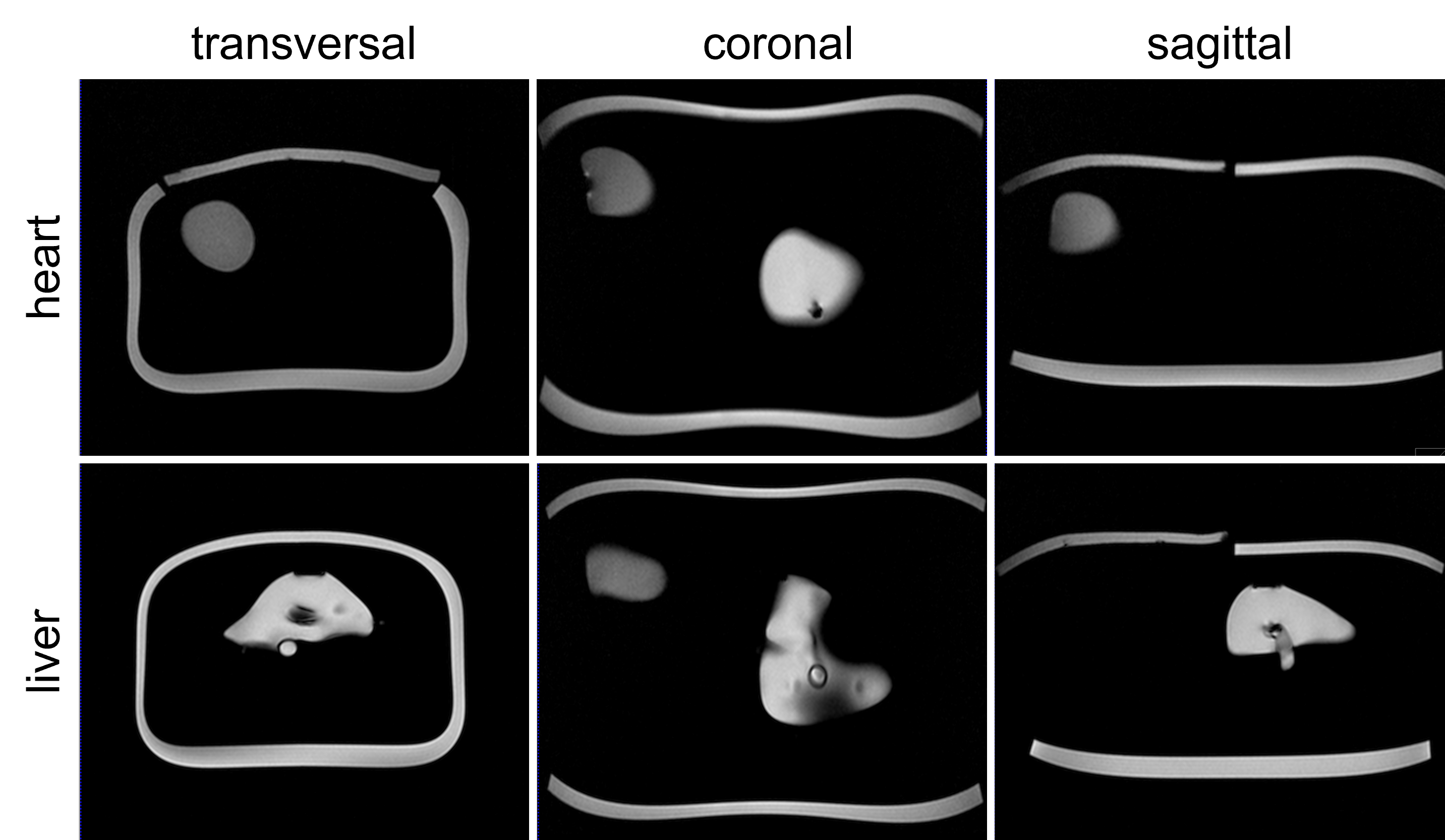
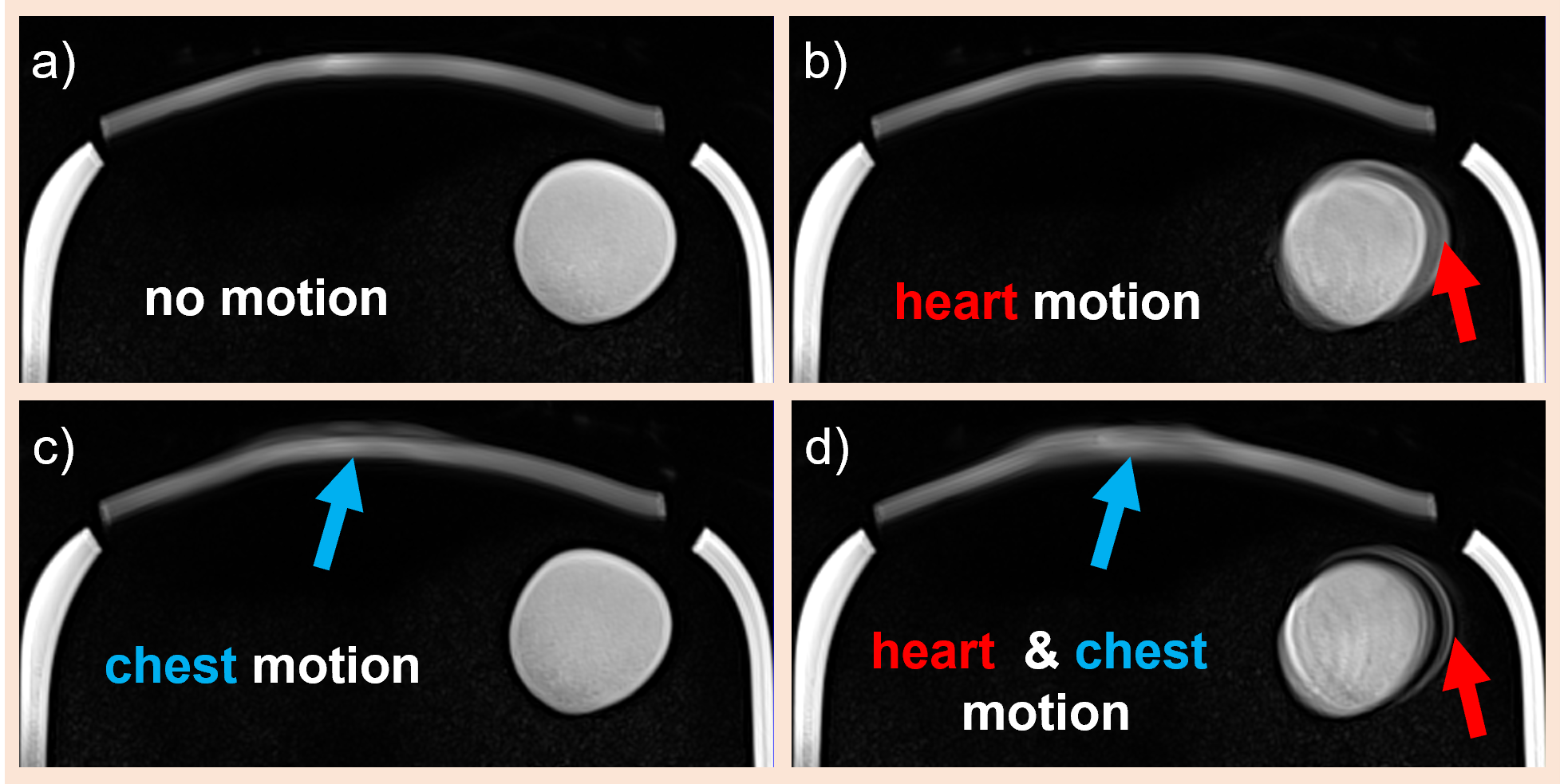
The phantom was assembled, placed on a support plate, and first MR data were acquired without motion resulting in artifact-free images, see Fig. 3. The currently operational motion DOFs (1 & 3) were tested while running a T1-weighted sequence for approx. 1 min; resulting images with motion artifacts are shown in Fig. 4.Discussion and Conclusion
Besides adding the gear box for abdominal organ motion, future work includes a detailed characterization of the achievable accuracy and reproducibility. The modular design would permit us to exchange, for example, the current simple heart model with a more advanced version including flow.Expected benefits in comparison to other torso phantoms featuring both, breathing and cardiac motion4,5, are higher accuracy thanks to the piezo stages and the possibility of clearly separating cardiac, chest and diaphragm motion.
The phantom is mostly constructed from low-cost components with standard plastic processing techniques (milling, 3D printing). Exceptions are the custom-made outer shell and the piezo stages, which could be replaced by a rectangular box and 3D printed pneumatic stepper motors6 (reduced accuracy and speed), respectively. We plan to make the CAD files of the phantom openly available once all modules are operational and fully tested.
Acknowledgements
This work was funded by Austrian Science Fund (FWF) no. P37189-N and no. P35305-B, as well as the Focus Grants “T4MR” and “NoLimit” from CMPBME, MedUni Vienna.References
1. Zaitsev, M., Maclaren, J. & Herbst, M. Motion artifacts in MRI: A complex problem with many partial solutions. J. Magn. Reson. Imaging 42, 887–901 (2015).
2. Runge, V. M., Richter, J. K. & Heverhagen, J. T. Motion in Magnetic Resonance: New Paradigms for Improved Clinical Diagnosis. Invest. Radiol. 54, 383–395 (2019).
3. Woletz, M., Roat, S., Hummer, A., Tik, M. & Windischberger, C. Technical Note: Human tissue-equivalent MRI phantom preparation for 3 and 7 Tesla. Med. Phys. 48, 4387–4394 (2021).
4. Swailes, N. E., MacDonald, M. E. & Frayne, R. Dynamic phantom with heart, lung, and blood motion for initial validation of MRI techniques. J. Magn. Reson. Imaging 34, 941–946 (2011).
5. Fieseler, M. et al. A dynamic thorax phantom for the assessment of cardiac and respiratory motion correction in PET/MRI: A preliminary evaluation. Nucl. Instrum. Methods Phys. Res. Sect. Accel. Spectrometers Detect. Assoc. Equip. 702, 59–63 (2013).
6. V. Groenhuis & S. Stramigioli. Rapid Prototyping High-Performance MR Safe Pneumatic Stepper Motors. IEEEASME Trans. Mechatron. 23, 1843–1853 (2018).
Figures