1225
Detunable Wireless Litzcage Coil for Human Head MRI at 1.5T1Research center, Sino Canada Health Institute Inc., Winnipeg, Manitoba, Canada, Winnipeg, MB, Canada, 2Department of Physics, The University of Winnipeg, Winnipeg, MB, Canada, 3Department of Electrical and Computer Engineering, Vanderbilt University, Nashville, TN, United States, 4Brain Imaging and Metabolic Research, The University of Winnipeg, Winnipeg, MB, Canada, 5Hubei Key Laboratory of Intelligent Conveying Technology and Device, Hubei Polytechnic University, Huangshi, China, 6Physical Examination Center, The Affiliated Hospital of Inner Mongolia Medical University, Hohhot, China, 7Sino Canada Health Engineering Research Institute (Hefei) Ltd, Hefei, China, 8Department of Radiology and Radiological Sciences, Vanderbilt University Medical Center, Nashville, TN, United States, 9Vanderbilt University Institute of Imaging Science, Vanderbilt University Medical Center, Nashville, TN, United States
Synopsis
Keywords: Non-Array RF Coils, Antennas & Waveguides, RF Arrays & Systems, Wireless Coil, Detune, Litzcage, Birdcage, RF Coil.
Motivation: Detuning wireless volume coils is challenging due to their complex structure, multiple resonant modes and multiple detuning circuits.
Goal(s): Developing an efficient method to geometrically decouple from the body coil
Approach: Designing an inductive birdcage coil featuring a figure-of-eight conductor pattern within the rungs, conducting volunteer and phantom image for compare its performance with the body coil and a receive array.
Results: The wireless Litzcage coil offers ~3.9 times higher SNR than the body coil. A 10% boost in the central area, a 21% reduction at the surface, and similar head image quality compared to a commercial 12-channel Head coil.
Impact: Applies to 0.55T, 3.0T, and 7T MRI systems, and expands to extremity, breast and body imaging. Simplifies coil design, improves detuning, and lowers costs. Lightweight and user-friendly, enabling MRI-guided therapy and streamlined clinical processes.
INTRODUCTION
Inductive RF coils provide a cost-effective and simple approach for creating wireless RF coils in MRI1-5. They streamline MR scan setup and enhance patient comfort by eliminating the need for bulky components like cables, baluns, preamplifiers, and connectors. However, volume-type wireless coils are usually operated in transmit/receive mode due to their complex structure and multiple resonant modes. Adding multiple detuning circuits to these coils would decrease the SNR and increase costs. In this work, we proposed an innovative inductive wireless volume coil based on the Litzcage6 design for 1.5 T head imaging.METHODS
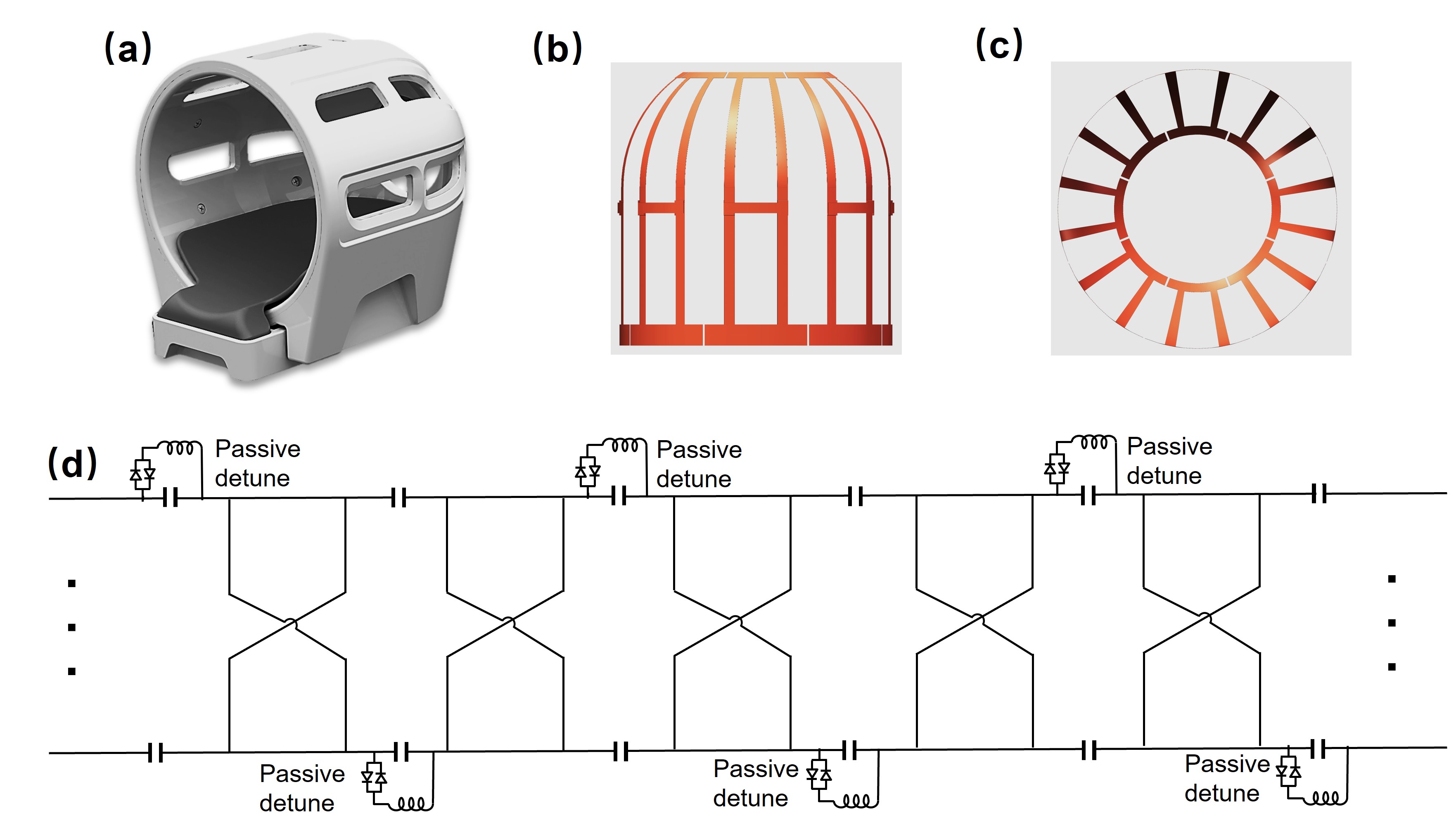
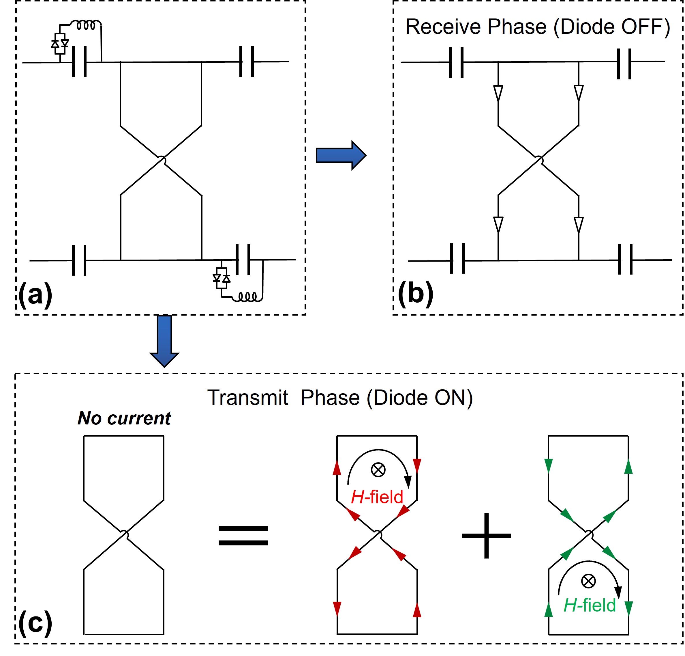
A uniquely designed wireless birdcage coil was constructed for head imaging, incorporating a Figure-of-Eight (Fo8) conductor pattern within its 16 rungs, each measuring 26.5 cm, the diameter of the cylindrical tube is 26 cm, eight passive detune circuits were employed (Figure1) and equivalent detune circuit of the wireless coil as shown in Figure2.During the receive phase, the cross-diodes remain OFF, the wireless coil operates in the Litzcage volume resonator mode, as shown in Figure 2(b).
In the transmit phase, uniform transverse magnetic-field flux passing through the upper and lower segments of the Fo8 loops induces counteracting currents, successfully achieving geometric decoupling from the body coil. Furthermore, passive detune circuits are utilized to decouple the remaining sections of the coil from the body coil, as shown in Figure 2(c).
To quantitatively evaluate the extent of RF transparency of the wireless coil to the body coil, a set of EM simulations was performed using FEM-based Maxwell solver (Ansys HFSS) 7 The wireless Birdcage and Litzcage coils were simulated on a cylindrical surface rather than replicating the complex domed structure for simplicity. To evaluate detuning performance, the B1+ of the body coil was compared in scenarios with and without the detuned wireless coils, and the coil configurations were documented in Figure 3 Table 1. All MR measurements were performed using a 1.5T whole-body scanner (Siemens MAGNETOM Sempra).
RESULTS
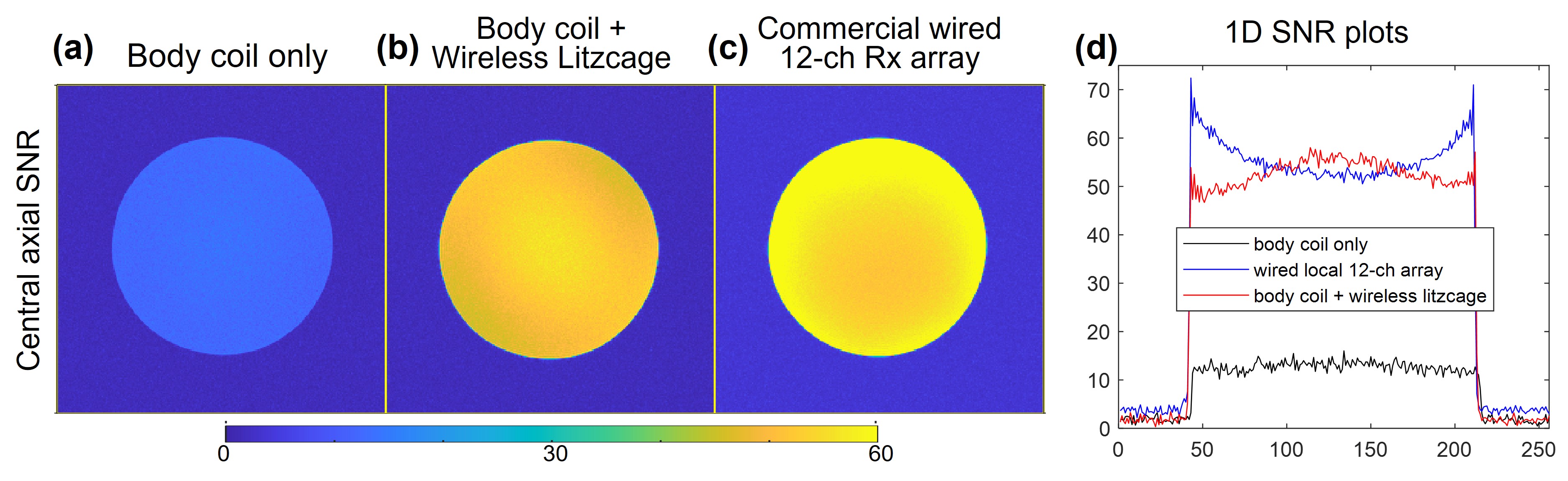
The wireless coil operating frequency was 63.67 MHz. The unloaded Q-factor was ~350 and was ~35 with a human head. Figure 3 shown simulated normalized B1+ field of the body coil without (a)and with the presence of wireless coils (b-e). The system's RF power calibration shows a minimal 0.2% difference with and without the wireless Litzcage coil, indicating its near invisibility in the transmit phase. This aligns with the simulation results in Figure 3(e).Phantom image SNR maps were generated by processing gradient-recalled echo (GRE) images reconstructed from raw data. Individual receive channel images were combined using the commonly used "Sum-of-Squares" (SoS) technique. The wireless coil exhibited approximately 3.9 times higher SNR compared to the body coil. Notably, there was a 10% increase in SNR in the central region and a 21% decrease at the surface when compared to a 12-channel receive array, as depicted in Figure 4 (a)- (c) and 1D SNR plot in Figure 4 (d).
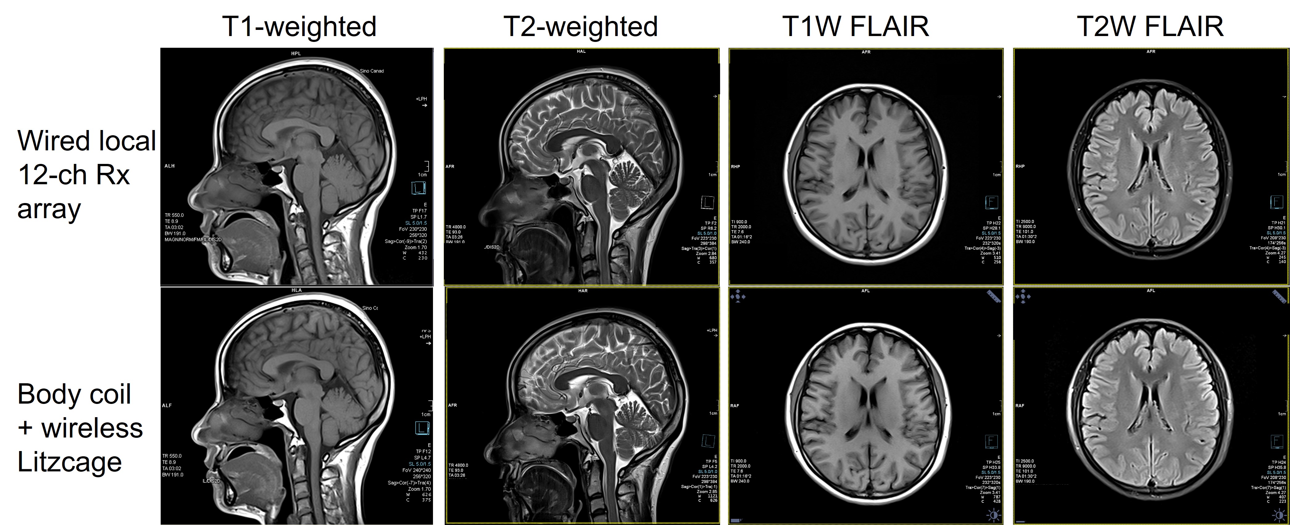
Figure 5 shows T1/T2-weighted and FLAIR images for the same healthy female volunteer. The wireless Litzcage provided similar image quality when compared to the commercial 12-channel wired local array. The high degree of image uniformity could also validate that the wireless coil was adequately detuned during the transmit phase, ensuring the uniform transmit field of the body coil remained unaffected.
DISCUSSION
The wireless coil is suitable for most applications without compromising patient safety in Rx-only mode. For specific areas like the knee and other body parts where phase wrap needs to be avoided, the Tx/Rx mode (no detune circuit) is appropriate. The wireless Litzcage coil has limitations for parallel imaging with the current MRI system setup. Alternative approaches such as compressive sensing or deep learning techniques can be explored in such cases.CONCLUSION
The domed wireless Litzcage coil offers comparable image quality to a wired receive array while being simple, lightweight, and cost-effective in design. This technology can be extended for application in MRI systems of 0.55T, 3.0T, and 7T. It is applicable for extremity, breast, and body imaging, enhancing patient comfort and allowing more flexible patient positioning. Different types of inductive wireless coils might outperform wired coils in MRI-guided intraoperative and interventional procedures, such as laser and microwave ablation surgeries.Acknowledgements
No acknowledgement found.References
- H.H. Quick, H. Kuehl, G. Kaiser, S. Bosk, J.F. Debatin, M.E. Ladd, Inductively coupled stent antennas in MRI, Magnetic Resonance in Medicine. 48 (2002) 781–790. https://doi.org/10.1002/mrm.10269.
- H. Zhu, G. Wang, L. Petropoulos, Multi-element wireless stacked phased array coil, in: ISMRM, 2012: p. 2660.
- H. Zhu, M. Fallah-Rad, M. Lang, W. Schellekens, K. Champagne, L. Petropoulos, A novel multichannel wireless receive phased array coil without integrated preamplifiers for high field MR imaging applications, in: ISMRM, 2012: p. 2788.
- A. Alipour, A.C. Seifert, B.N. Delman, P.M. Robson, R. Shrivastava, P.R. Hof, G. Adriany, Z.A. Fayad, P. Balchandani, Improvement of magnetic resonance imaging using a wireless radiofrequency resonator array, Sci Rep. 11 (2021) 23034. https://doi.org/10.1038/s41598-021-02533-3.
- M. Lu, S. Chai, H. Zhu, X. Yan, Low-cost inductively coupled stacked wireless RF coil for MRI at 3 T, NMR in Biomedicine. 36 (2023) e4818. https://doi.org/10.1002/nbm.4818.
- F.D. Doty, G. Entzminger, C.D. Hauck, Error-Tolerant RF Litz Coils for NMR/MRI, Journal of Magnetic Resonance. 140 (1999) 17–31. https://doi.org/10.1006/jmre.1999.1828.
- C.E. Hayes, The development of the birdcage resonator: a historical perspective, NMR in Biomedicine. 22 (2009) 908–918. https://doi.org/10.1002/nbm.1431
Figures