1224
Simultaneous MRI and Ultrasound Imaging on a High-performance Gradient Platform1GE HealthCare, Niskayuna, NY, United States, 2University of Iowa, Iowa City, IA, United States, 3University of Wisconsin-Madison, Madison, WI, United States, 4University of Michigan, Ann Arbor, MI, United States
Synopsis
Keywords: MR-Guided Interventions, MR-Guided Interventions
Motivation: Simultaneous ultrasound (U/S) and MR imaging has been reported on whole-body MRI systems with conventional gradients (CVG) but remains unexplored on high-performance gradient (HPG) platforms.
Goal(s): We assessed the MR and U/S image quality, alongside thermal impact on an MR-compatible U/S probe at CVG and HPG configurations.
Approach: Fast spoiled gradient echo imaging, echo planar imaging (EPI), B0-field map and U/S probe temperature were measured.
Results: Moderate-to-severe susceptibility-induced signal loss (due to U/S probe) extended ~8 mm into phantom at gradient isocenter with no visible U/S image artifacts. A substantial temperature rise was observed on U/S probe during EPI at HPG configuration.
Impact: This study evaluates and compares image quality and thermal risks of simultaneous MR and U/S imaging on a high-performance gradient system versus a conventional clinical system. Our findings can help optimize the protocols for image-guided U/S intervention using high-performance gradients.
Introduction
Using an MRI-compatible research ultrasound (U/S) probe on a whole-body MRI system, simultaneous MR and U/S imaging has been demonstrated for the purpose of mitigating the effects of motion on the accuracy of image-guided therapy1,2. MRI scanners equipped with high-performance gradients (HPG) combine high gradient amplitudes (Gmax) and high maximum slew rates (SRmax) to enable high-resolution MRI with reduced susceptibility artifacts3–5. For example, the MAGNUS gradient system can simultaneously deliver a Gmax and SRmax of 300 mT/m and 750 T/m/s respectively3. However, multimodal MR and U/S imaging on an HPG MRI system remains unexplored. Here, we assess MR and U/S image quality, and the temperature rise in an MRI-compatible U/S probe at conventional gradient (CVG) and HPG configurations.Materials and Methods
A multi-tissue U/S phantom (Model 040GSE, Zerdine® Hydrogel) was used for all MR and U/S imaging.Ultrasound Imaging
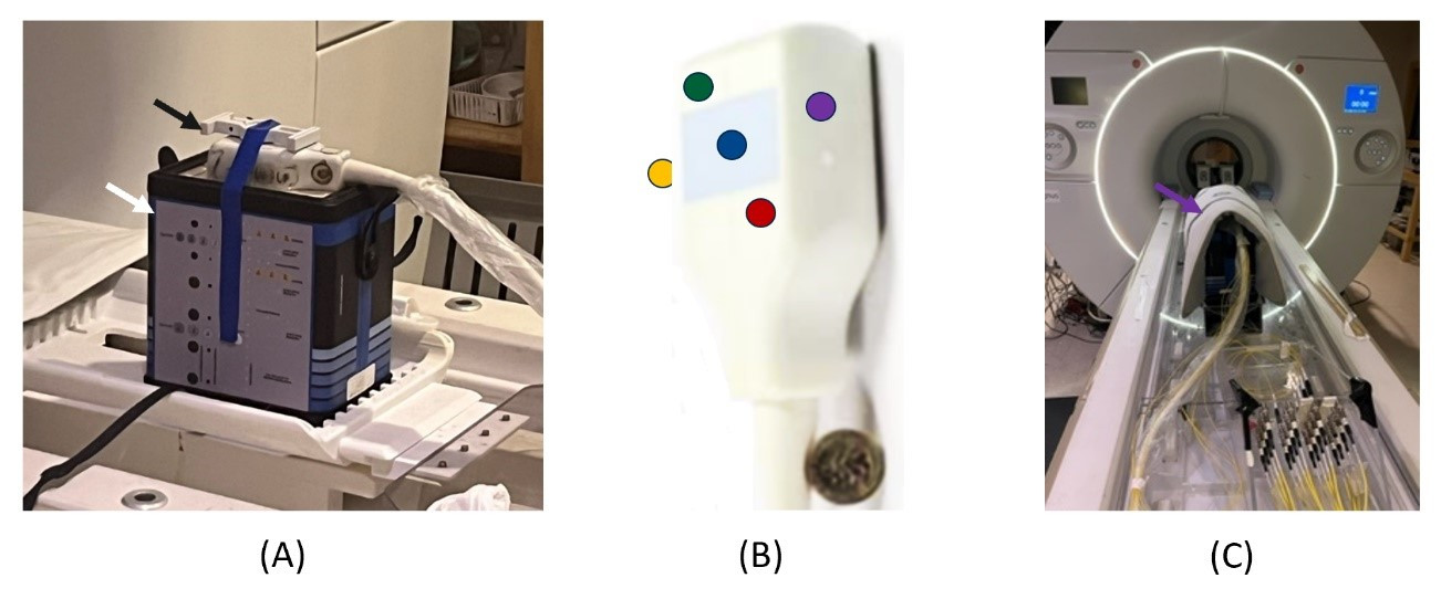
All U/S imaging was carried out on a 4D system (Vivid E95, GE Healthcare) equipped with a hands-free MR-compatible E4D research probe1. 4D U/S images of the phantom were acquired in harmonic imaging mode (1.7/3.3 MHz) as shown in Figure 1A.
Temperature Measurement
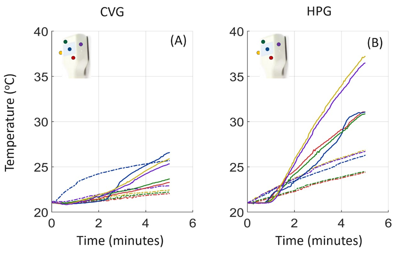
The U/S probe surface temperature was measured during multimodality imaging using fiber optic temperature sensors placed on the surface of the probe (Figure 1B). A 10-minute wait time was allowed between each temperature measurement to permit convective cooling of the U/S probe. All temperature measurements were normalized to start at the ambient scanner room temperature (~21oC).
Magnetic Resonance Imaging
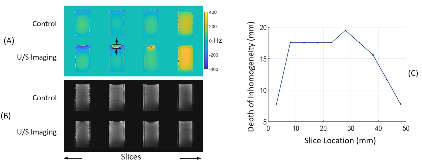
All MRI HPG experiments were carried out on a MAGNUS gradient system (GE Healthcare, Waukesha, WI) at Gmax=300 mT/m and SRmax=750 T/m/s. Imaging at CVG configuration was achieved by derating the MAGNUS system to operate at Gmax and SRmax of 100 mT/m and 200 T/m/s respectively. RF signal transmit and reception were achieved using the integrated body coil and a 20-channel AIR anterior coil array (GE Healthcare) respectively (Figure 1C). To assess the B0 inhomogeneity induced by the U/S probe, a 2D B0-field map was obtained during U/S imaging using the following parameters: FOV=25 cm, TE/TR=3.4 ms/100 ms, voxel size=1.95x1.95x5 mm3, slices=40, average(s)=1. A control B0 map without the U/S probe was also acquired with identical parameters. For U/S probe surface temperature measurement and image quality assessment, multi-phase fast spoiled gradient echo (FSPGR) images were obtained at CVG and HPG configurations for a duration of 5 mins with parameters: FOV=250 mm, voxel size=1.95x1.95x5 mm3, slices=10, TE/TR=0.9 ms/3.0 ms, bandwidth=±31.25 kHz, temporal resolution=4 s. EPI scans with identical parameters were obtained at bandwidth=±500 kHz using HPG (TE/TR=8.9 ms/32.0 ms, temporal resolution=0.32 s and echo spacing=0.3 ms) and CVG (TE/TR=14 ms/44.0 ms, temporal resolution=0.44 s/phase and echo spacing=0.6 ms) configurations.
Results and Discussion
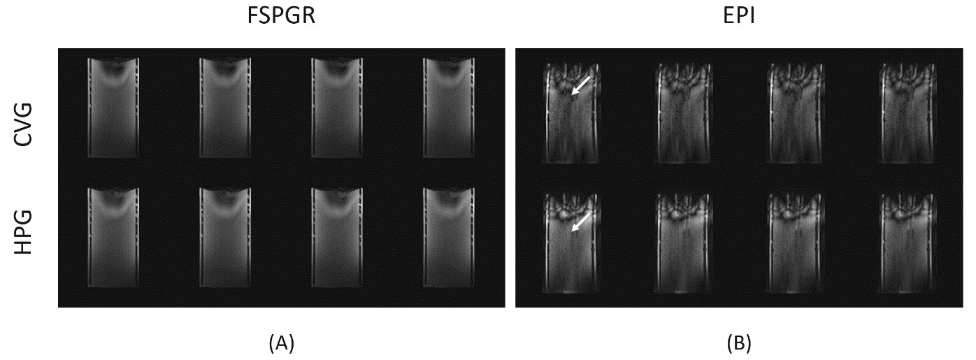
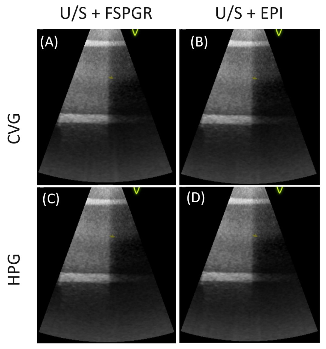
Representative slices from B0 maps and their corresponding magnitude images show regions of higher B0 inhomogeneity around the location of the U/S probe (Figure 2A and 2B). The regions of higher inhomogeneity are not visible in the control images as the U/S probe was removed from the phantom. The depth of the B0 inhomogeneity on the phantom was maximum (19.5 mm) at 28 mm from the gradient isocenter (Figure 2C). FSPGR and EPI MRI images obtained during temperature mapping on the surface of the U/S probe at CVG and HPG configurations are shown in Figure 3. There was no visible difference between the FSPGR images obtained at CVG and HPG configurations (Figure 3A). However, EPI distortion artifacts in the acquisitions at CVG configuration were more severe compared to HPG configuration due to the shorter ESP enabled by the latter (Figure 3B). There is also no significant difference in the U/S images obtained during multimodal imaging at CVG and HPG configurations (Figure 4). The temperature changes during the multimodal scans stayed below 28 oC except for the EPI scans carried out at HPG configuration (Figure 5). The U/S probe surface temperature reached ~38 oC at the sides of the probe. This increased temperature can be associated with higher gradient-induced eddy currents on metallic components in the U/S probe at higher SRmax. The eddy current heating at HPG configurations needs to be addressed in future work to fully utilize the higher SRmax of HPGs for EPI acquisitions during simultaneous MR-U/S imaging.Conclusion
High-performance gradient systems can be utilized for rapid simultaneous MR-U/S FSPGR and EPI imaging with lesser distortion compared to conventional gradient configurations. However, there is a need for mitigation of eddy current induced heating in EPI at High-performance gradient configuration.Acknowledgements
Research reported in this work was supported by the National Institute of Health under award numbers R01CA266879 and R01CA190298.References
1. Bednarz, B. P. et al. First-in-human Imaging Using a MR-compatible e4D Ultrasound Probe for Motion Management of Radiotherapy. Phys Med 88, 104–110 (2021).
2. Lee, W. et al. A Magnetic Resonance Compatible E4D Ultrasound Probe for Motion Management of Radiation Therapy. IEEE Netw 2017, 10.1109/ULTSYM.2017.8092223 (2017).
3. Foo, T. K. F. et al. Highly efficient head-only magnetic field insert gradient coil for achieving simultaneous high gradient amplitude and slew rate at 3.0T (MAGNUS) for brain microstructure imaging. Magnetic Resonance in Medicine 83, 2356–2369 (2020).
4. Setsompop, K. et al. Pushing the limits of in vivo diffusion MRI for the Human Connectome Project. Neuroimage 80, 220–233 (2013).
5. Weiger, M. et al. A high-performance gradient insert for rapid and short-T2 imaging at full duty cycle. Magn Reson Med 79, 3256–3266 (2018).
Figures