1223
Twstr: A Resonant, Matched MRI Coil without any Discrete Components1EECS, University of California, Berkeley, Berkeley, CA, United States
Synopsis
Keywords: RF Arrays & Systems, RF Arrays & Systems, Implantable Coils, Flexible Coils
Motivation: Component-less MRI coils have the potential to increase the strength and flexibility of array elements making them suitable for implantables, multi-modal imaging, and body conformal applications.
Goal(s): As a result, this work strives to demonstrate a resonant, matched MRI coil without the use of discrete components.
Approach: A Twstr coil is composed of a single Twisted-Pair wire manipulated by twisting and cutting such that the coil presents a match at its resonant frequency.
Results: Twstr coils have a high quality factor, similar SNR performance in a Rx-Only configuration, and outstanding TRx capabilities when compared to a standard loop coil.
Impact: Twstr coils are component-less, flexible MRI coils made from a single piece of Twisted-Pair wire. Such coils eliminate the need for discrete components on a coil providing a viable solution for implantable and multi-modal imaging coils without compromising performance.
Purpose
The true flexibility, thickness, and stability of an MRI coil is limited by its interface board. This hinders their potential to be used as implantable coils1,2, or in multi-modal imaging systems where space is limited3,4. Additionally, fragile surface mount components on the interface board can be damaged exposing the subject to harsh RF conditions5. Eliminating the interface board and subsequent components is crucial for space constraint applications and safety.Flexible resonant structures have been used extensively to build MRI coils6-10. However, they are typically matched with lossy/fragile surface mount components. Rather than using surface mount components for matching11, the resonant structure can be extended to provide a match at resonance.
In this work we introduce Twstr (Fig.1), a thin and flexible component-less MRI coil made from a single Twisted-Pair wire12,13 that requires no additional components for tuning/matching and provides a transmission line length to offset the $$$Q$$$-Spoiling circuit and preamplifier.
Methods
Twstr coils are designed to resonate at the Larmor Frequency and provide a power/noise match using a single Twisted-Pair wire. A Twisted-Pair wire is cut to a length equal to $$$l_{wire}=2r_c+2l_f$$$, where $$$r_c$$$ is the radius of the loop and $$$l_f$$$ is the length of the braid used for matching. Figure 2 describes the assembly of the coil where the following condition must be satisfied for a match.$$Z_{in}(\omega)=\frac{1}{R_c^2 |Y|^2}+\frac{j\omega}{|Y|^2}\cdot\left(\frac{1}{\omega^2 L_c}-\frac{2|Y|^2}{\omega^2C_t^{\prime}l_f}-\left(C_b^{\prime}l_f+\frac{C_{t}^{\prime}\pi r_c}{2}\right)\right), Z_{in}(\gamma B_0)=R_{match}$$
$$|Y|^2=\frac{1}{R_c^2}+\omega^2\left(\frac{1}{\omega^2L_c}-\left(C_b^{\prime}l_f+\frac{C_{t}^{\prime}\pi r_c}{2}\right)\right)^2$$
The capacitance per unit length of the wire ($$$C_t^{\prime}$$$) and of the feed braid ($$$C_b^{\prime}$$$) can be modulated by adjusting the turn length (Fig. 2b). As a result, the wire can be manipulated via cutting and twisting to yield a coil that provides a match without additional components.
This procedure was used to generate two 7.5cm diameter coils (an Rx-only variant and a TRx coil) using 22-gauge polytetrafluoroethylene (PTFE) insulated Twisted-Pair wire. Both coils were compared to a control coil of the same size in terms of electrical and imaging performance. The Rx-only Twstr coil utilized broadband detuning while the control coil used resonant detuning (Fig.3a,b). A double-probe measurement was used to characterize detuning performance and quality factor of each coil. Imaging performance was characterized using a 3T GE MR750W system (Waukesha, WI) with the coils placed on a spherical loading phantom. Flip angle maps [TR/TE/FA=52ms/4ms/30°,M:128×128,SL:7mm,BW=244Hz/Pixel] were used to further characterize Rx-only detuning and TRx excitation performance. SNR maps14 were computed using PD-weighted images [TR/TE/FA=6s/7ms/30°,M:256×256,SL:5mm,BW=122Hz/Pixel].
Results
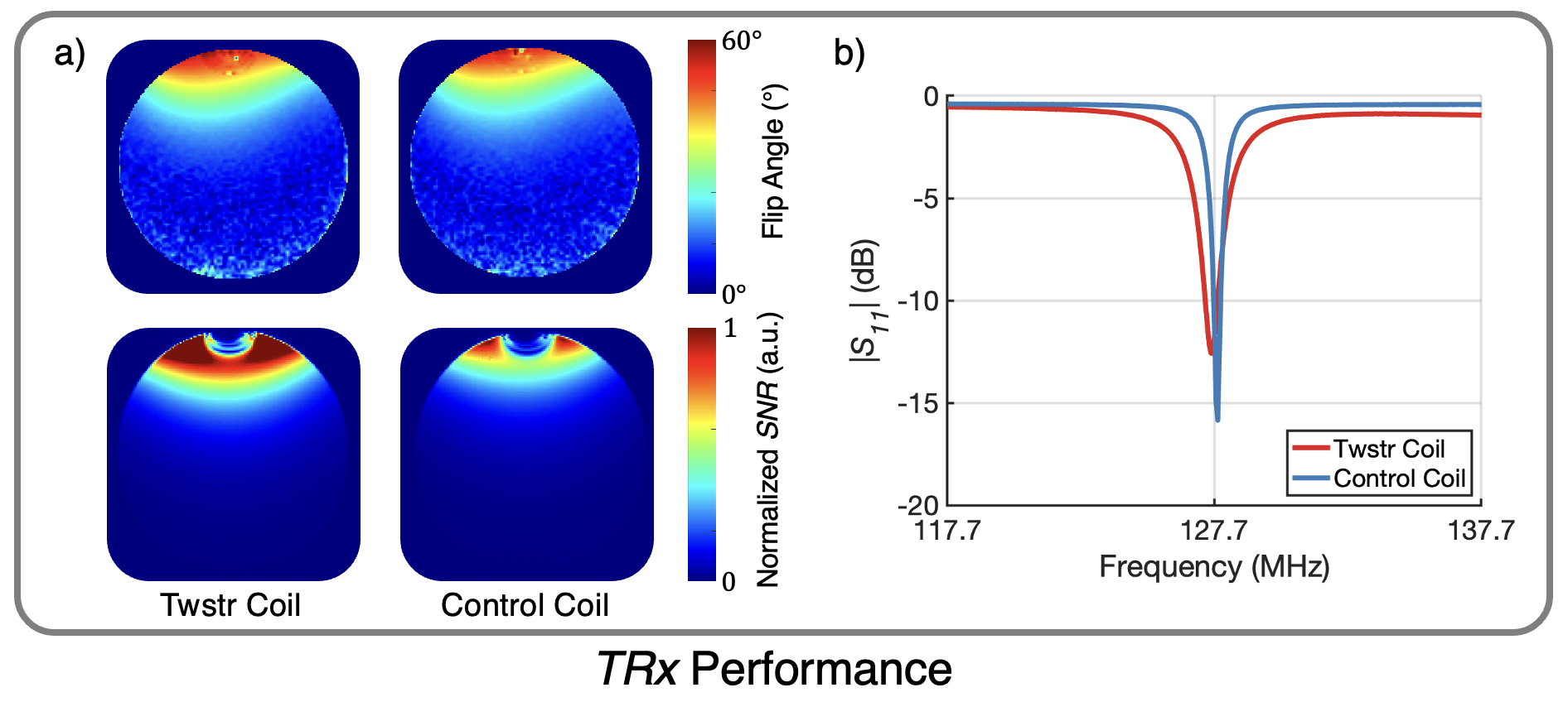
The two 7.5cm diameter Twstr coils were resonant at 127.7MHz having adequate return loss (<-12dB) without the need for additional elements (Fig.5b). Broadband detuning achieves 36dB of isolation for the Rx-only Twstr coil, while resonant detuning on the control coil had 50dB (Fig.3a,b). Flip angle maps reveal adequate detuning performance with similar variation between the two Rx-only coils (Fig.3c), and they share similar SNR/quality factor (Fig.4). In the case of TRx, both coils achieve the desired excitation profile, but increased SNR is revealed when using a Twstr coil (Fig.5).Discussion
Assembly of Twstr coils is extremely versatile. Altering the wire gauge, insulation thickness, and turn lengths of the Twisted-Pair wire modulates the capacitance per unit length. Additionally, the tuning range is extended by adding alternating cuts along the wire to reduce series capacitance. Use of low-loss insulating material guarantees that coil losses are dominated by conductor loss. As a result, the Twstr and control coils share a similar quality factor and SNR performance does not degrade by using Twisted-Pair capacitors over ceramic ones (Fig.4). Broadband detuning of a Twstr coil does not require any additional tuning at the cost of reduced isolation. However, this is improved by modifying the detuning circuit to provide a resonant short during Tx.In the case of TRx, Tx performance is identical between the two coils. However, TRx SNR is higher for the Twstr coil. While the return loss (|$$$S_{11}$$$|) is similar between Twstr and the control coil, the match presented by Twstr has more bandwidth thus retaining better return loss across various loading conditions15. Therefore, the increased matching bandwidth from Twstr resulted in a more favorable match during scanning. This reduced the added noise from the preamplifier thus increasing the overall SNR. In all, the data reveals that Twstr coils have the potential to be used in space constraint applications without sacrificing imaging performance.
Conclusion
Twstr coils achieve similar SNR, Tx, and detuning performance when compared to a standard loop coil. Additionally, the component-less nature of Twstr coils makes them suitable in applications where extreme thinness, flexibility, and rigidity are necessary. We expect Twstr coils to impact the implementation of flexible arrays, and implantable coils.Acknowledgements
We would like to acknowledge support from R01MH127104, U01EB029427, and U01EB023829. Julian Maravilla acknowledges the NSF for funding under DGE 2146752.References
- Logothetis, Nikos K., et al. "Ultra high-resolution fMRI in monkeys with implanted RF coils." Neuron 35.2 (2002): 227-242.
- Janssens, Thomas, et al. "An implanted 8-channel array coil for high-resolution macaque MRI at 3 T." Neuroimage 62.3 (2012): 1529-1536.
- Peters, Judith C., et al. "On the feasibility of concurrent human TMS-EEG-fMRI measurements." Journal of Neurophysiology 109.4 (2013): 1214-1227.
- Navarro de Lara, Lucia I., et al. "A novel coil array for combined TMS/fMRI experiments at 3 T." Magnetic resonance in medicine 74.5 (2015): 1492-1501.
- Panych, Lawrence P., and Bruno Madore. "The physics of MRI safety." Journal of Magnetic Resonance Imaging 47.1 (2018): 28-43.
- Maravilla, Julian Adolfo, et al. "Transmission Line Receiver Coils (TLCs) for MRI." Proceedings of the 30th scientific meeting, International Society for Magnetic Resonance in medicine, London. Vol. 189. 2022.
- Zhang, Bei, Daniel K. Sodickson, and Martijn A. Cloos. "A high-impedance detector-array glove for magnetic resonance imaging of the hand." Nature biomedical engineering 2.8 (2018): 570-577.
- Ruytenberg, Thomas, Andrew Webb, and Irena Zivkovic. "Shielded‐coaxial‐cable coils as receive and transceive array elements for 7T human MRI." Magnetic resonance in medicine 83.3 (2020): 1135-1146.
- Cogswell, Petrice M., et al. "Application of adaptive image receive coil technology for whole-brain imaging." AJR. American journal of roentgenology 216.2 (2021): 552.
- General Electric Co. US20190353722A1
- Reykowski, Arne, Steven M. Wright, and Jay R. Porter. "Design of matching networks for low noise preamplifiers." Magnetic resonance in medicine 33.6 (1995): 848-852.
- Lefferson, Peter. "Twisted magnet wire transmission line." IEEE Transactions on Parts, Hybrids, and Packaging 7.4 (1971): 148-154.
- Karasan, Ekin, et al. "Caterpillar traps: A highly flexible, distributed system of toroidal cable traps." Magnetic Resonance in Medicine 89.6 (2023): 2471-2484.
- Kellman, Peter, and Elliot R. McVeigh. "Image reconstruction in SNR units: a general method for SNR measurement." Magnetic resonance in medicine 54.6 (2005): 1439-1447.
- Lau, Buon Kiong, et al. "Impact of matching network on bandwidth of compact antenna arrays." IEEE Transactions on Antennas and Propagation 54.11 (2006): 3225-3238.
Figures