1215
Reduction of Radiofrequency Induced Heating around Passive Implants via Flexible Metasurface Shielding at 7T1Center for Advanced Metabolic Imaging in Precision Medicine, Department of Radiology, University of Pennsylvania, Philadelphia, PA, United States, 2Magnetic Detection and Imaging group, TechMed Centre, University of Twente, Enschede, Netherlands, 3Department of Oral and Maxillofacial Surgery, University of Pennsylvania, Philadelphia, PA, United States, 4Department of Orthopedic Surgery, University of Pennsylvania, Philadelphia, PA, United States
Synopsis
Keywords: Safety, Safety
Motivation: Metallic implant compatibility at ultra-high field strengths (≥7T) continues to be often contraindicated as RF induced heating can result in surrounding tissue damage. Metasurface technology has been shown in the past to locally null the B1+ field, thereby providing a potential solution for shielding implants.
Goal(s): To demonstrate a metasurface based method for shielding metallic implants to reduce RF heating.
Approach: Eight implants were tested in a polyacrylic acid (PAA) phantom using a high-SAR sequence with and without a prototype metasurface.
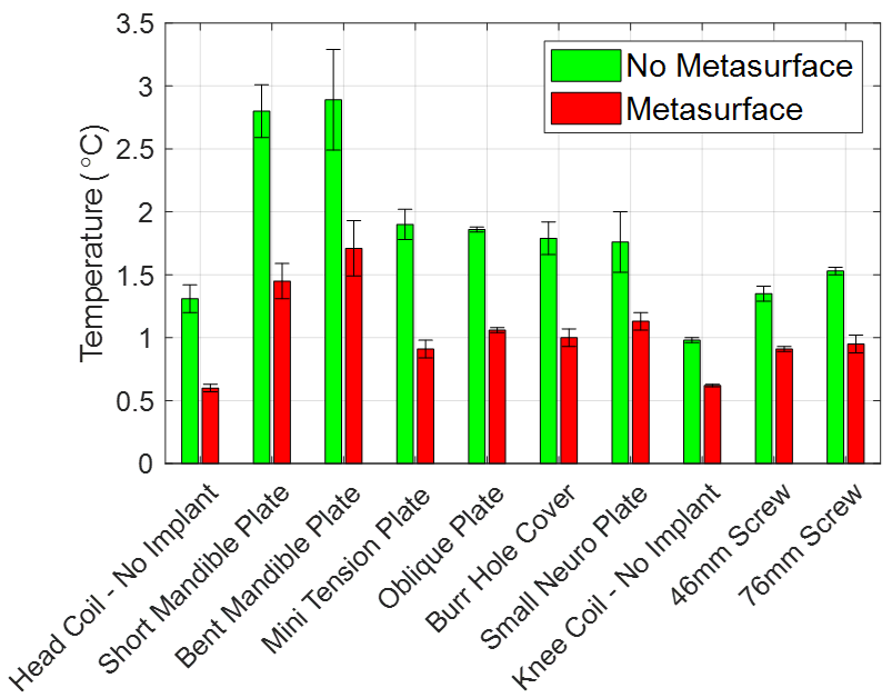
Results: On average the metasurface design reduced RF induced implant heating in the phantom by 41.6%.
Impact: Patient undergoing invasive brain or trauma surgeries typically have passive metallic devices placed, making them unable to receive MRI scans at ultra-high field strengths due to RF induced heating. This work benefits this patient population by reducing RF heating.
Introduction
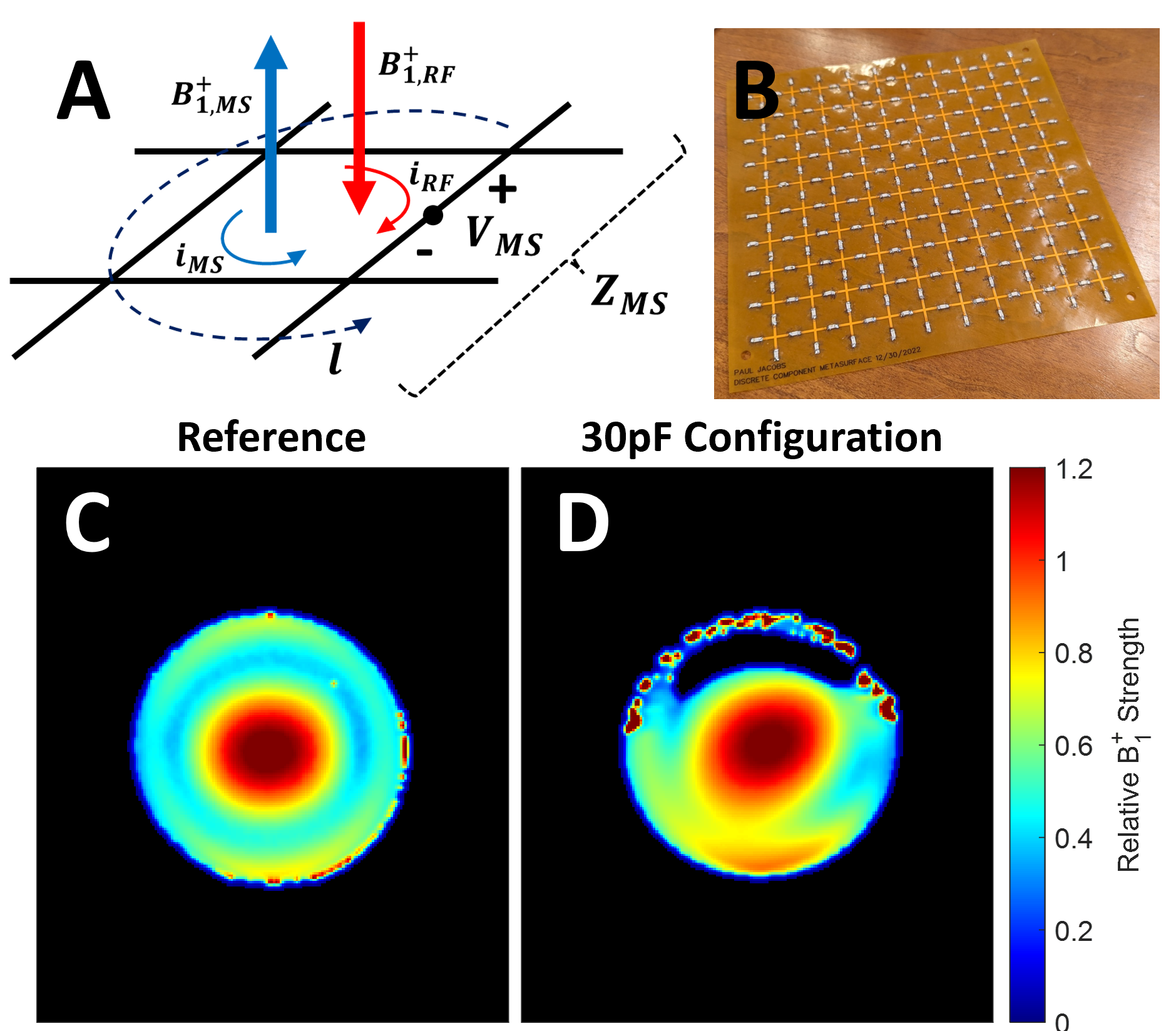
Most passive metallic implants are contraindicated for MR Imaging due to potential amplification of radiofrequency (RF) induced heating that results from the interaction with the transmit RF field. Compatibility of implants with ultra-high field (≥7T) MRI continues to be an ongoing research focus, with current mitigation strategies ranging from novel RF coil designs1,2 to modifying the implants themselves3-6. However, these approaches call for substantial hardware modifications from scanner and implant manufacturers. Metasurfaces have become increasingly popular for improving B1+ homogeneity, by tuning their design to produce an in-phase current distribution that enhances the B1+ in adjacent areas7,8. A less common approach is to to produce a nulled B1+ field in their vicinity due to an out-of-phase current distribution8,9, as illustrated in Figure 1a. The goal of this work was to assess the potential of this mechanism to reduce local implant heating at 7T.Methods
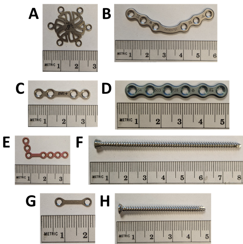
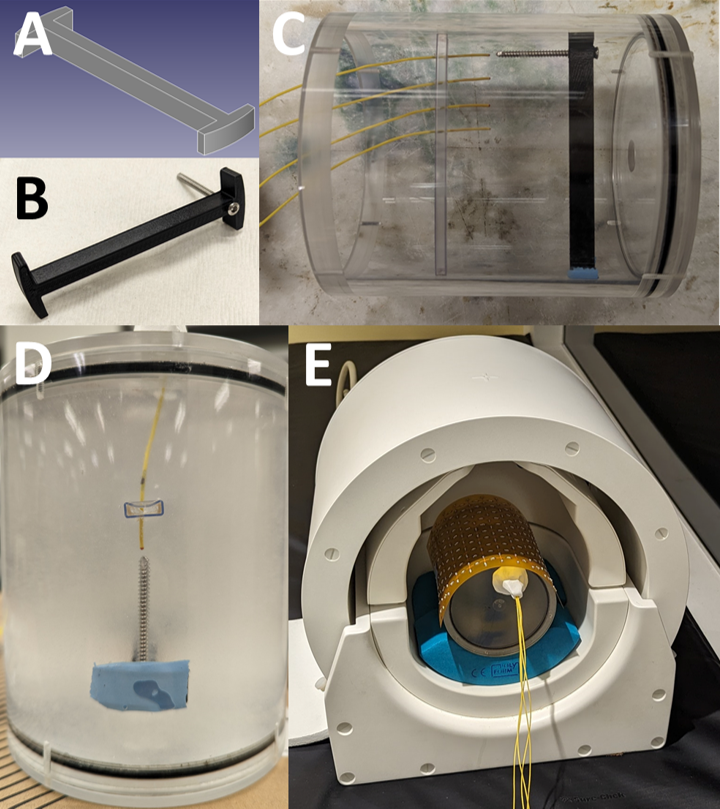
A series of 21 prototypes 18x18cm2 flexible metasurfaces were tested (Figure 1b) with a discrete capacitor value (ranging from 0.5-75pF). B1+ mapping in each design was performed as described in Volz et al.10 using a saline phantom on a 7T system (MAGNETOM Terra, Siemens Healthcare) equipped with a single-channel transmit/32-channel phased array head coil (Nova Medical) (Figure 3e). Eight types of metallic implants, seen in Figure 2a-h, were fixed inside a custom 3D printed holder (Figure 3a and 3b) and placed inside a cylindrical polyacrylic acid (PAA) phantom (10g/L PAA, 1.32 g/L NaCl, 800mL H2O) with four fiber optic probes evenly spaced in 10mm increments in the region directly below the metasurface and relative to the implant (approximately 2mm away from the distal end) (Figure 3c and 3d). The two orthopedic screws (Figure 2f and 2h) were scanned using a single-channel transmit/28-channel phased array proton knee coil (Quality Electrodynamics). A high SAR (>95%) GRE scan was run over the course of 20-minutes to assess the temperature rise in the surrounding phantom medium. This experiment was repeated with and without the metasurface present and three times per implant to assess the experimental variability.Results
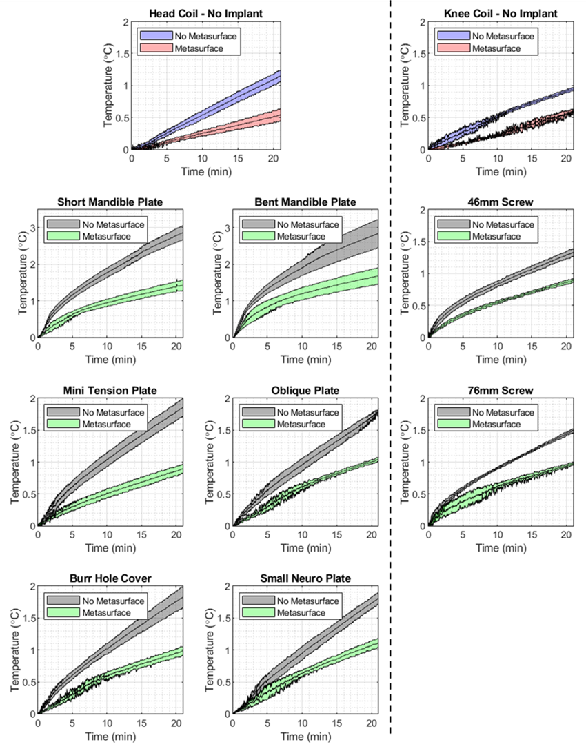
The metasurface testing showed that 30pF produced the highest amount of B1+ nulling in comparison to the reference configuration (Figure 1c and 1d). Fiber optic temperature measurements showed the highest magnitude of heating occurred in probe 1, closest to the implant. Time series temperature data from probe 1, seen in Figure 4, shows that the rate of heating was reduced when the metasurface was present across all implants tested. A direct comparison of the maximum temperature difference at the end of the 20-minute scan period can be seen in Figure 5, showing reduced RF heating when the metasurface was present. Quantitatively, the metasurface was able to decrease the observed local heating of the implants tested by an average of 0.84°C or 41.6% and without an implant by an average of 0.53°C or 45.2%.Discussion
This work primarily focused on demonstrating a prototype metasurface that can null the B1+ field locally and hence shield passive metallic implants to reduce RF induced heating. It can also be seen that the overall B1+ away from the metasurface is preserved quite well indicating in vivo imaging should also be minimally affected in those areas. The implants tested here were chosen for being relatively small and being able to easily fit inside the nulled region created by the metasurface. Furthermore, the superficial placement of many of the craniofacial implants in patients render them particularly suitable for shielding in view of the metasurface penetration depth. There have been other studies that have aimed to reduce implant heating by modifying the RF coil1,2 or by modifying the implant itself3-6, all of which would require substantial effort from the manufacturers and would not benefit current patients. One of the primary limitations of this work is that the current design may not be able to address heating of larger implanted devices, such as hip replacements, which are primarily heated via gradients11,12. Future work aims to produce a more flexible metasurface that incorporates parallel plate capacitors and assessing their usage in in vivo image quality and effectiveness.Conclusion
In this work we demonstrate that a metasurface can be configured to null the B1+ field and reduce RF induced heating around passive implants. We found that all eight passive implants tested showed a temperature reduction on average of 0.84°C of 41.6%.Acknowledgements
Research reported in this work was supported by the National Institute of Biomedical Imaging and Bioengineering of the National Institutes of Health under award number P41EB029460. 3D printed objects printed courtesy of the University of Pennsylvania Libraries' Holman Biotech Commons.References
1. Golestanirad L, Iacono MI, Keil B, et al. Construction and modeling of a reconfigurable MRI coil for lowering SAR in patients with deep brain stimulation implants. Neuroimage. Feb 15 2017;147:577-588. doi:10.1016/j.neuroimage.2016.12.056
2. Golestanirad L, Kazemivalipour E, Keil B, et al. Reconfigurable MRI coil technology can substantially reduce RF heating of deep brain stimulation implants: First in-vitro study of RF heating reduction in bilateral DBS leads at 1.5 T. PLoS One. 2019;14(8):e0220043. doi:10.1371/journal.pone.0220043
3. Golestanirad L, Angelone LM, Kirsch J, et al. Reducing RF-induced Heating near Implanted Leads through High-Dielectric Capacitive Bleeding of Current (CBLOC). IEEE Trans Microw Theory Tech. Mar 2019;67(3):1265-1273. doi:10.1109/TMTT.2018.2885517
4. Espiritu J, Berangi M, Yiannakou C, et al. Evaluating metallic artefact of biodegradable magnesium-based implants in magnetic resonance imaging. Bioact Mater. Sep 2022;15:382-391. doi:10.1016/j.bioactmat.2021.11.035
5. Nordbeck P, Fidler F, Friedrich MT, et al. Reducing RF-related heating of cardiac pacemaker leads in MRI: implementation and experimental verification of practical design changes. Magn Reson Med. Dec 2012;68(6):1963-72. doi:10.1002/mrm.24197
6. Li D, Ji X, Zheng J, Pan C, Chen J, Kainz W. A Novel Design of Implantable Esophageal Stent to Reduce the MRI RF-Induced Heating. IEEE Transactions on Electromagnetic Compatibility: IEEE; 2017. p. 805-812.
7. Vorobyev V, Shchelokova A, Efimtcev A, et al. Improving B1+ homogeneity in abdominal imaging at 3 T with light, flexible, and compact metasurface. Magn Reson Med. Jan 2022;87(1):496-508. doi:10.1002/mrm.28946
8. Dubois M, Leroi L, Raolison Z, et al. Kerker Effect in Ultrahigh-Field Magnetic Resonance Imaging. Phys Rev X. Sep 27 2018;8(3)doi:ARTN 031083 10.1103/PhysRevX.8.031083
9. Park BS, Guag JW, Jeong H, Rajan SS, McCright B. A new method to improve RF safety of implantable medical devices using inductive coupling at 3.0 T MRI. MAGMA. Aug 11 2023;doi:10.1007/s10334-023-01109-8
10. Volz S, Noth U, Rotarska-Jagiela A, Deichmann R. A fast B1-mapping method for the correction and normalization of magnetization transfer ratio maps at 3 T. Neuroimage. Feb 15 2010;49(4):3015-26. doi:10.1016/j.neuroimage.2009.11.054
11. Winter L, Seifert F, Zilberti L, Murbach M, Ittermann B. MRI-Related Heating of Implants and Devices: A Review. Journal of Magnetic Resonance Imaging2020. p. 1-20.
12. Zilberti L, Arduino A, Bottauscio O, Chiampi M. The underestimated role of gradient coils in MRI safety. Magnetic Resonance in Medicine. Jan 2017;77(1):13-15. doi:10.1002/mrm.26544
Figures