1143
Gradient-Free Frequency Encoded MRI1Biomedical Engineering, Case Western Reserve University, Cleveland, OH, United States, 2Computer Science, University of Washington, Seattle, WA, United States, 3Biomedical Engineering, Vanderbilt University, Nashville, TN, United States, 4Radiology, Case Western Reserve University, Cleveland, OH, United States
Synopsis
Keywords: New Trajectories & Spatial Encoding Methods, Data Acquisition, low-field MRI, RF encoding, New spatial encoding, Bloch Siegert shift, STAR
Motivation: Eliminating conventional gradients can help miniaturize and lower costs of MRI significantly. No method using RF-gradients has been able to achieve frequency encoding, the fastest encoding mechanism in MRI.
Goal(s): Develop a Simultaneous-Transmit-and-Receive (STAR) system and perform RF Frequency encoding using the Bloch Siegert shift.
Approach: A novel injection transformer, 2MHz/47.5mT RF coil setup and pulse sequence was developed to enable STAR to prevent the RF encoding signal from overwhelming the receiver while frequency encoding MR signal without conventional gradients.
Results: The novel STAR system achieved 99.75% cancellation of RF encoding signal, enabling the first-ever acquisition of frequency encoded MR images using RF-gradients.
Impact: We have demonstrated, for the first time ever, frequency encoded MRI using RF field gradients in place of conventional B0 gradients. This is a fundamental requirement to make RF encoded-MR imaging as fast as conventional gradient encoding.
Introduction
Conventional MRI uses B0 gradients for spatial encoding, which are expensive, bulky, and prone to breakage. Several spatial encoding methods have been proposed that use RF gradients1-3 instead of B0 gradients for phase and slice encoding. However, frequency encoding, the fastest Fourier encoding mechanism in MRI, has never been achieved using RF gradients. RF gradient encoding using the Bloch Siegert (BS) shift4,5 has the potential to be used for frequency encoding since it can apply spatially dependent frequency shifts while magnetization stays in the transverse plane, which is necessary for simultaneous signal recording6. However, BS frequency encoding has not yet been achieved experimentally because it requires simultaneously transmitting the BS pulse while recording signal at nearby frequencies (Simultaneous-Transmit-and-Receive7,8 (STAR)). This work reports a 2MHz(47.5mT) RF gradient-based frequency encoding system comprising a novel injection transformer-based STAR system along with highly decoupled Tx encoding and Rx imaging coils and an imaging pulse sequence. The system and sequence were used to acquire the first-ever RF frequency encoded MR images.Methods
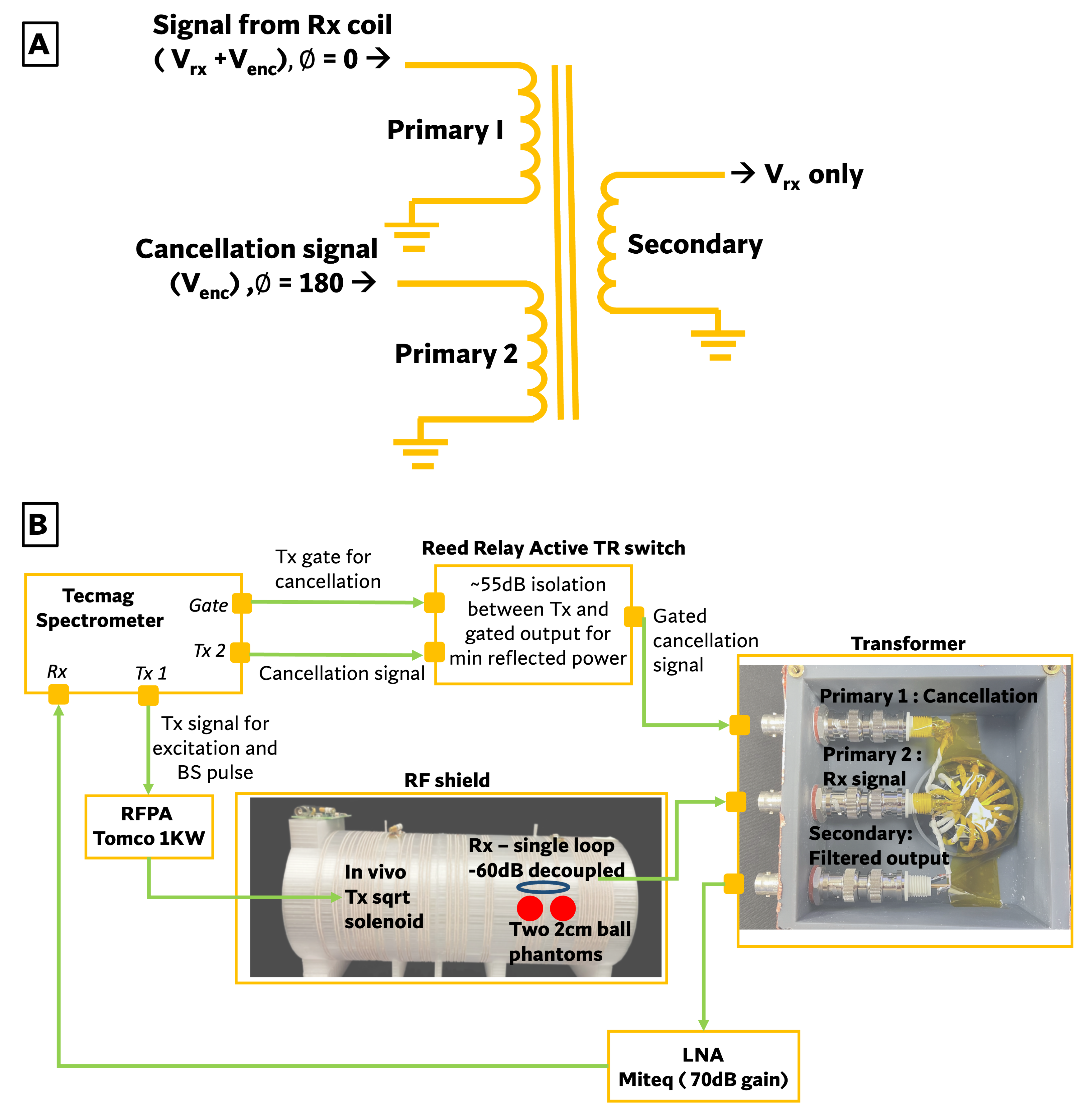
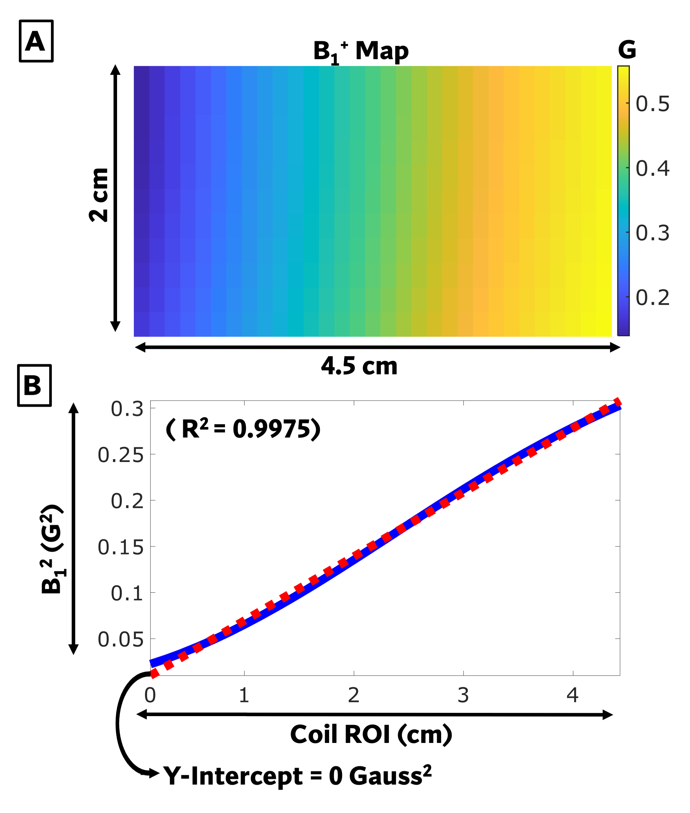
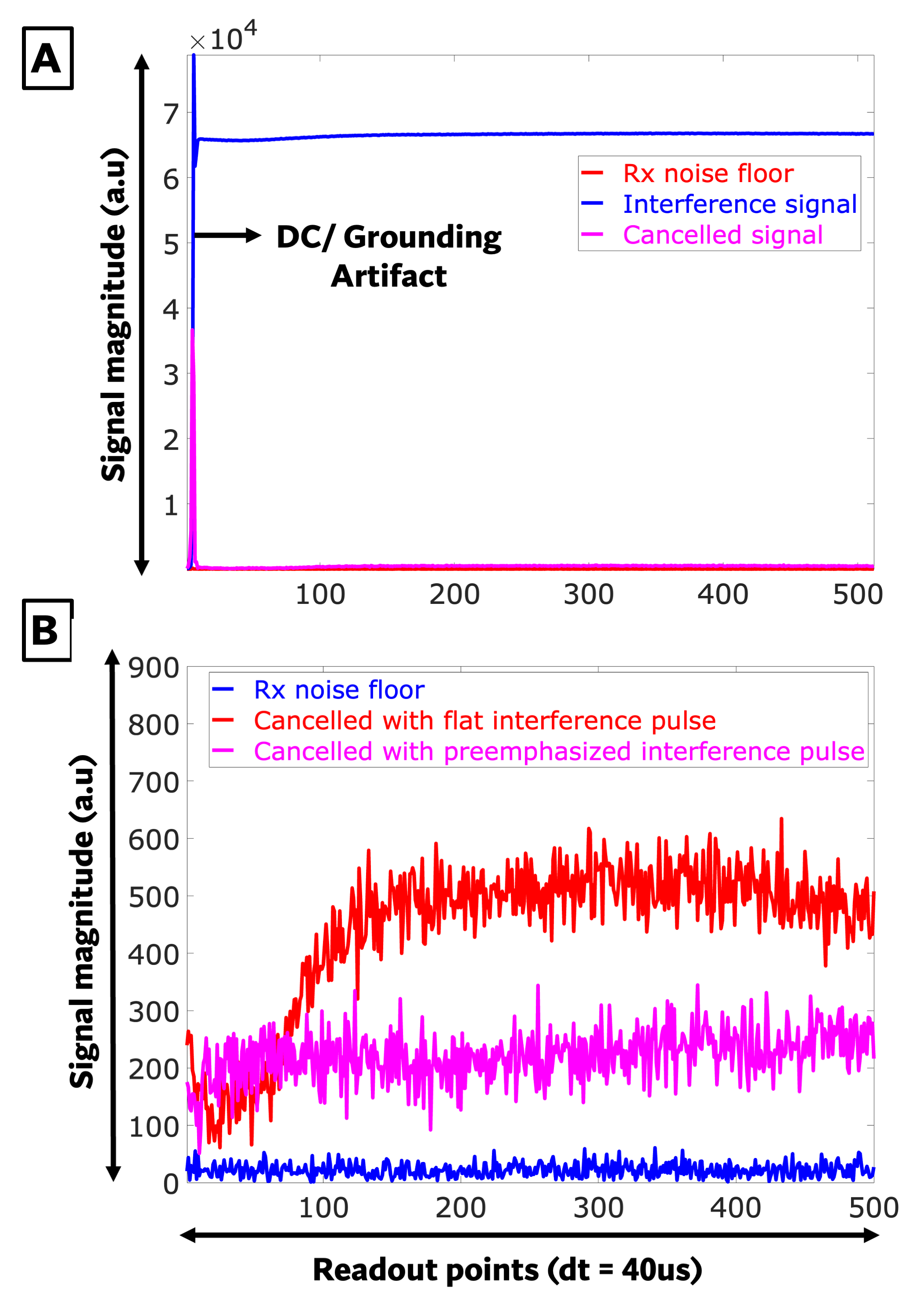
STAR hardware: To enable fully simultaneous transmission of the BS frequency encoding pulse while receiving NMR signal, a toroidal injection transformer with two primary windings and one secondary winding (Litz wire, 12 tri-windings, low-loss carbonyl iron core) was constructed to actively cancel out the signal induced in the receive coil from the encoding pulse before it reached the spectrometer (Figure 1A). To eliminate the encoding signal while preserving the NMR signal, the first primary winding comprises the MR signal from the imaging Rx coil combined with the leaked signal from the transmit coil that the imaging Rx coil sees. The second primary winding couples in a cancellation signal possessing the same magnitude as the encoding signal but with an opposite phase. The secondary winding then exclusively carries the NMR signal, without any presence of the encoding signal.Experimental Setup: An optimized RF coil9 (Figure 1B) was built for spatial encoding with a square root field shape. The B1+ map and B1+2 fields are shown in Figure 2A-B. A single loop coil was used as the imaging receive coil to image two 2cm mineral oil ball phantoms. The transmit and receive coils were >60dB decoupled. A Tecmag Redstone (Houston, TX, USA) spectrometer transmitted both the encoding and cancellation signals. Calibration of the cancellation pulse was done by adjusting its phase and amplitude to achieve maximum cancellation of the leaked signal. The BS encoding pulse was pre-emphasized so that the protons experienced a flat waveform, which also improved cancellation of the leaked signal since the cancellation signal was not pre-emphasized. The achieved cancelation is shown in Figure 3A and a comparison of cancelation with flat versus pre-emphasized encoding pulses is shown in Figure 3B.
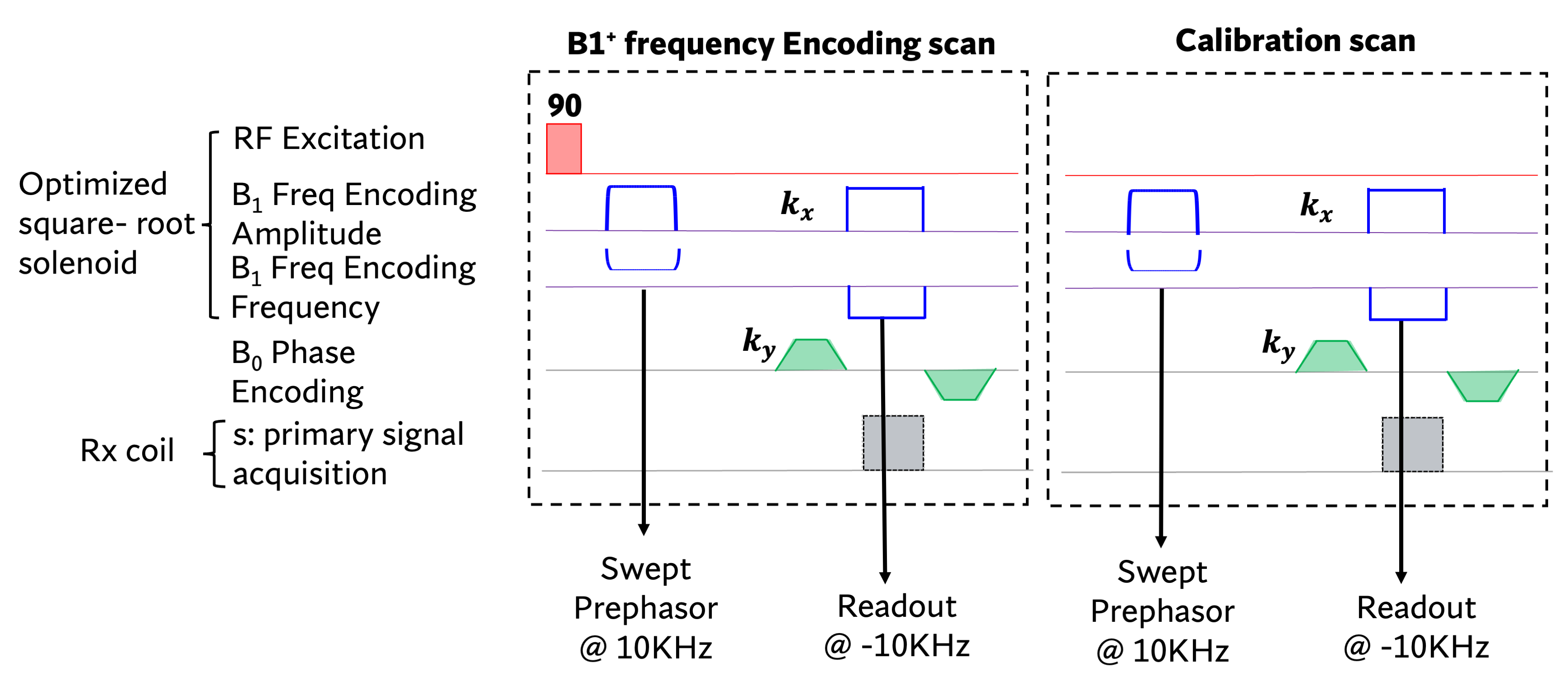
Imaging: Figure 4 shows the RF frequency encoded 2D GRE pulse sequence. The prephasor was a frequency swept BS spatial encoding pulse (10.7ms, KBS=56.38 rad/ G2) and the frequency encoding readout pulse was a flat BS encoding pulse (20.48ms, KBS=116.57 rad/ G2). Both pulses used opposite FM polarities. Sequence parameters were BS offset=10kHz, TR=462ms, TE=30.2ms, NRO=512, NPE=34, Imaging BW=25kHz. Each TR interleaved signal measurements with calibration measurements without an excitation pulse to enable subtraction of residual leakage signal. The maximum B1=0.55 G in the ROI and thus the Beff tilt angle was 0.25 rad causing negligible elliptical signal polarization6. Therefore, an iFFT reconstruction was used.
Results
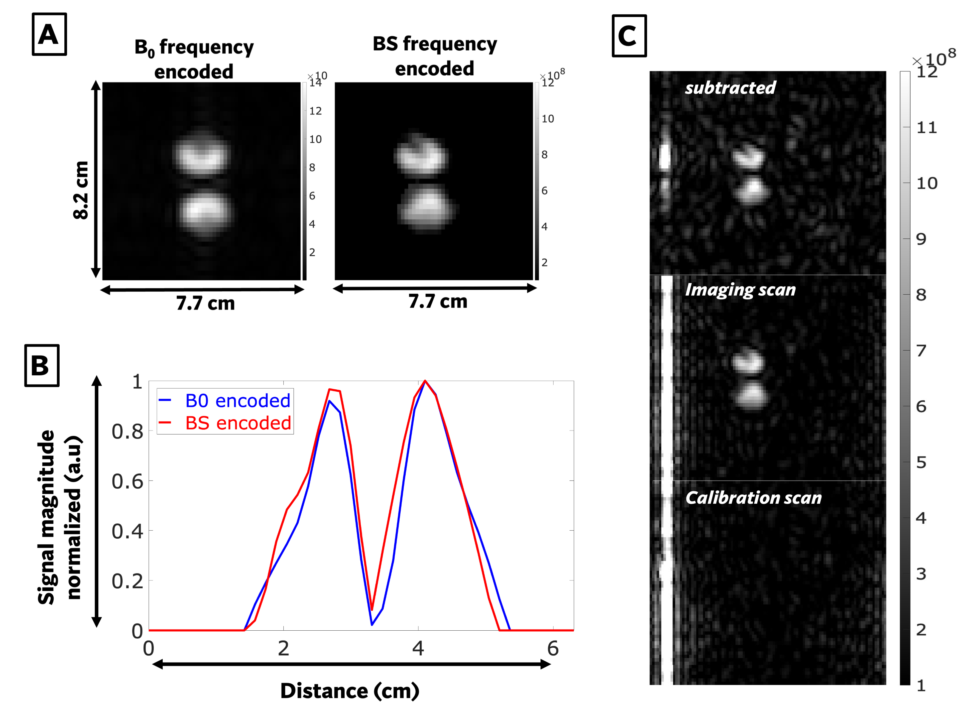
Via imaging tests, the STAR injection transformer was determined to be 96.5% efficient. The S21 between ports was -1.8dB (Attributed to connectors). No core heating was observed after 3 hours of continuous use. 99.75% leaked signal cancellation was achieved with this transformer setup with a 13W encoding pulse. Figure 5A shows the resulting BS frequency encoded image of the 2-ball phantom without subtraction of the calibration scan and a B0 frequency encoded image for reference. Figure 5B shows the 1D profiles of both the B0 and BS frequency encoded scans. Figure 5C shows the effectiveness of the calibration scan in removing additional leaked transmit signal. In this experiment the RF gradient frequency encoding achieved an effective frequency encoding gradient strength of 1.4G/m (with peak B1=0.55G, transmit coil current I=0.35A), and a spatial resolution of 8mm.Discussion
This work demonstrated a new hardware system for fully simultaneous transmission of a spatial encoding RF pulse during signal recording, which was used to perform spatial frequency encoding using RF gradients in place of conventional B0 gradients for the first time. Leveraging the BS shift for frequency encoding further enabled the use of a simple pulse sequence and an iFFT-based image reconstruction.Acknowledgements
The work is supported by NIH grant R01 EB 030414.References
[1] D. I. Hoult. J Magn Reson, 33(1):183–197, 1979.
[2] J. C. Sharp and S. B. King. Magn Reson Med, 63(1):151–161, 2010.
[3] Torres, E., Froelich et.al. Magn reson Med, 87(2):674–685, 2022.
[4] Bloch, F. and Siegert, A. Physical l Review, 57(6):522. 1940.
[5] W. A. Grissom, Z. Cao, and M. D. Does. J Magn Reson, 242:189–196, 2014.
[6] Cao Z, Chekmenev E, Grissom W. ISMRM, p4220,2014
[7] Selvaganesan, K., et.al. PLOS ONE, 18(6):e0287344, 2023.
[8] Ha, Y. ISMRM, p 0749,2020
[9] Srinivas SA et.al. ISMRM, p 1589, 2023.
Figures