1037
A 16-Channel Ankle Conformal Array Coil for Robot Assisted Dynamic Ankle Joint Imaging at 1.5T MRI1Institute of Medical Physics and Radiation Protection, TH Mittelhessen University of Applied Sciences, Gießen, Germany, 2Motionrad GmbH, Mainz, Germany, 3Formerly Rothman Institute Department of Orthopaedics, Thomas Jefferson University Hospital, Philadelphia, PA, United States, 4Diagnostic and Interventional Radiology, Philipps-University Marburg, Marburg, Germany
Synopsis
Keywords: RF Arrays & Systems, RF Arrays & Systems, MSK
Motivation: Many musculoskeletal disorders cannot be detected in static MRI, making surgical intervention necessary.
Goal(s): Our Goal was to enable motion controlled dynamic MRI to potentially add diagnostic findings and reduce surgical interventions.
Approach: We advanced our apparatus for controlled passive movement of the foot (Robotic Motion Device) and implemented an adapted 16-channel Ankle Coil for accelerated imaging.
Results: Combining the Robotic Motion Device and the 16-channel Ankle Coil allowed us to perform controlled passive foot movement and acquire high SNR images.
Impact: The combination of a Robotic Motion Device and an adapted 16-channel Ankle Coil enables dynamic image acquisition with controlled passive movement of the ankle joint, potentially adding and improving diagnostic findings and reducing surgical interventions.
Introduction
Numerous musculoskeletal disorders correlate strongly to pathomechanical motion patterns. While static MRI is commonly used in musculoskeletal (MSK) diagnostics to assess joint structure, it lacks functional information and misses many injuries, instabilities, or syndromes, as they only become apparent in motion or during stress.1-5 Elias et al. showed that controlled passive movements of joints and spine during real-time MRI are feasible and indispensable to trigger and depict pathomechanical patterns.1-5 To maximize dynamic joint MRI's potential, we aimed to develop an MRI-compatible robotic device with an integrated ankle conformal 16-channel coil array for controlled for dynamic imaging of the ankle and subtalar joint in a 1.5T MRI system.Methods
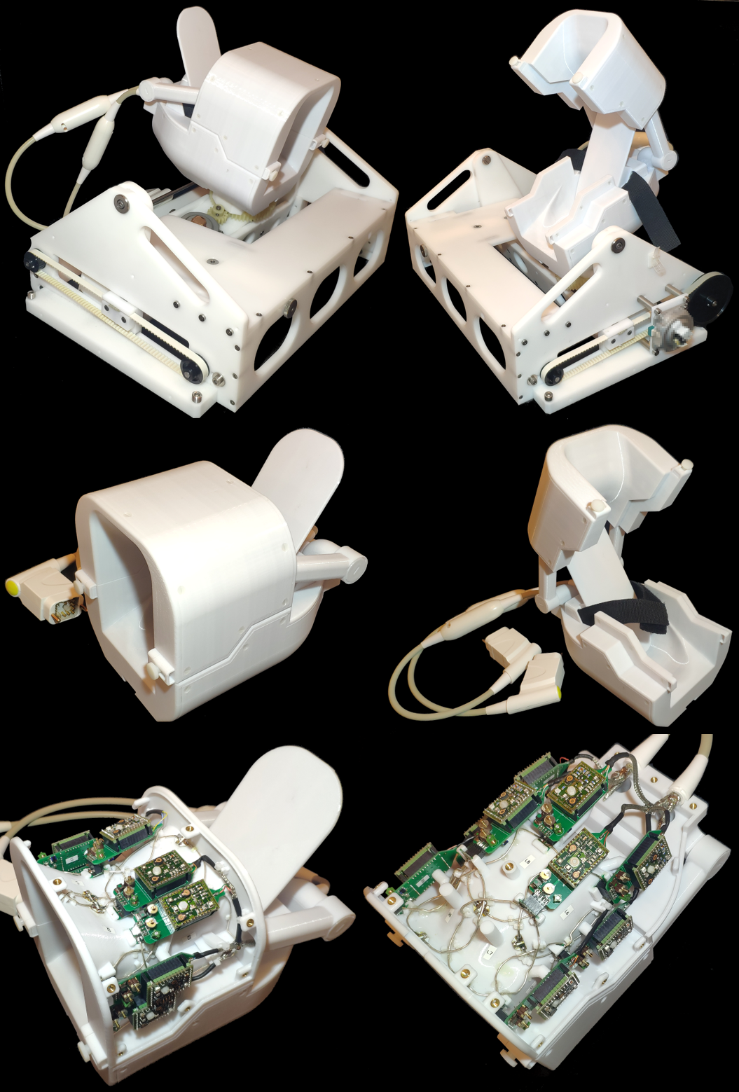
16-Channel Ankle Coil: The Coil has been designed to completely enclose the ankle joint while still allowing full physiological movement of the foot. The fore- and midfoot were left uncovered so that the foot can be fastened to the coil. The coil housing was divided into a hinged upper section for easier positioning of the foot. The upper coil segment houses 7 receives coil elements and a lower section consists of 9 elements. The coil array was desigend in the 3D CAD model with all the necessary support structures for the coil elements, preamplifier, and cable routing. All housing parts were 3D-printed from polycarbonate plastics (Fortus 360, Stratasys Ltd., Eden Prairie, MN, USA).The coil elements were constructed from 1.5mm thick, silver-coated copper wires and have an average diameter of approx. 80 mm. All adjacent neighboring elements were critically overlapped.6 Each coil element was connected to a preamplifier daughter board that includes a fuse and the networks for active detuning and impedance matching. RF bench-level metrics were used to optimize geometrical decoupling, matching, tuning, active detuning, and preamplifier decoupling.
Robotic Motion Device: The constructed coil with the secured fastened foot and ankle is then attached to a robotic motion device (RMD), which allowed for controlled passive movements (adjustable speed and range of motion) of the joints in two axes inside the scanner’s bore. Dorsal extension/plantarflexion of the foot as well as pronation/supination of the subtalar joint were controlled by the examiner from the control room using a wireless PS5 game controller. The RMD was actuated by non-magnetic piezo drives and received signals through the control system that uses WIFI transmission as well as optical signal from the control room into the MRI suite.
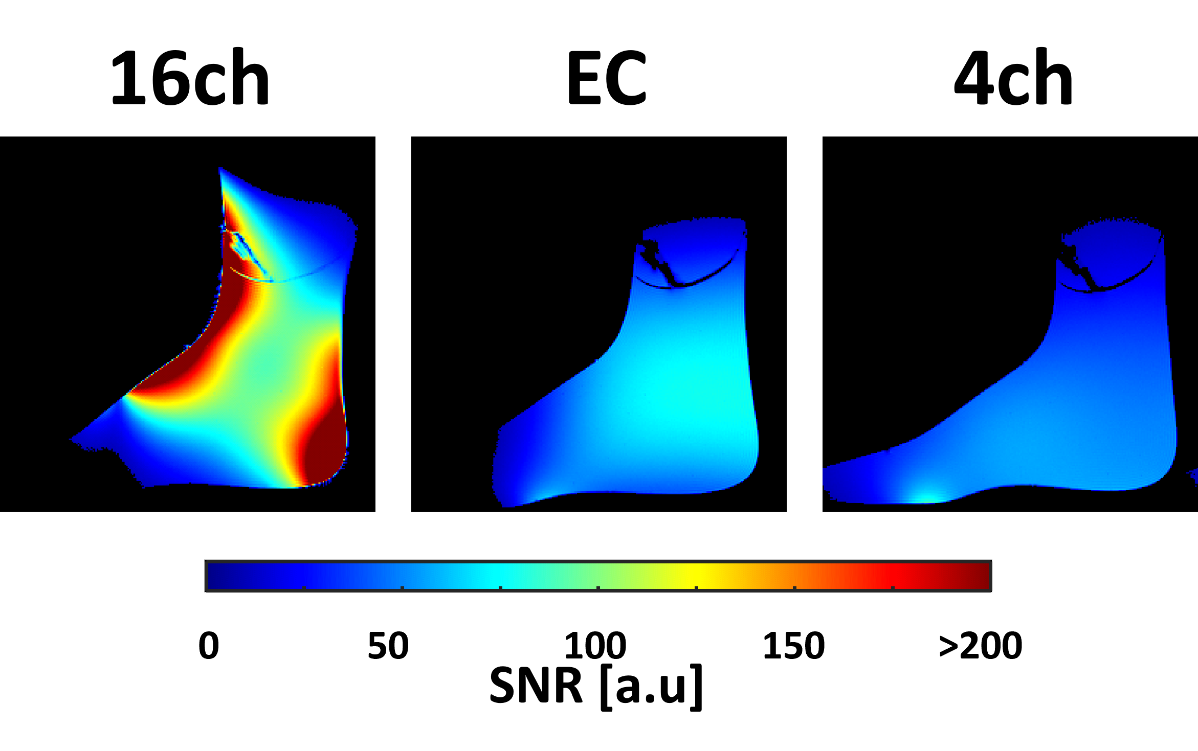
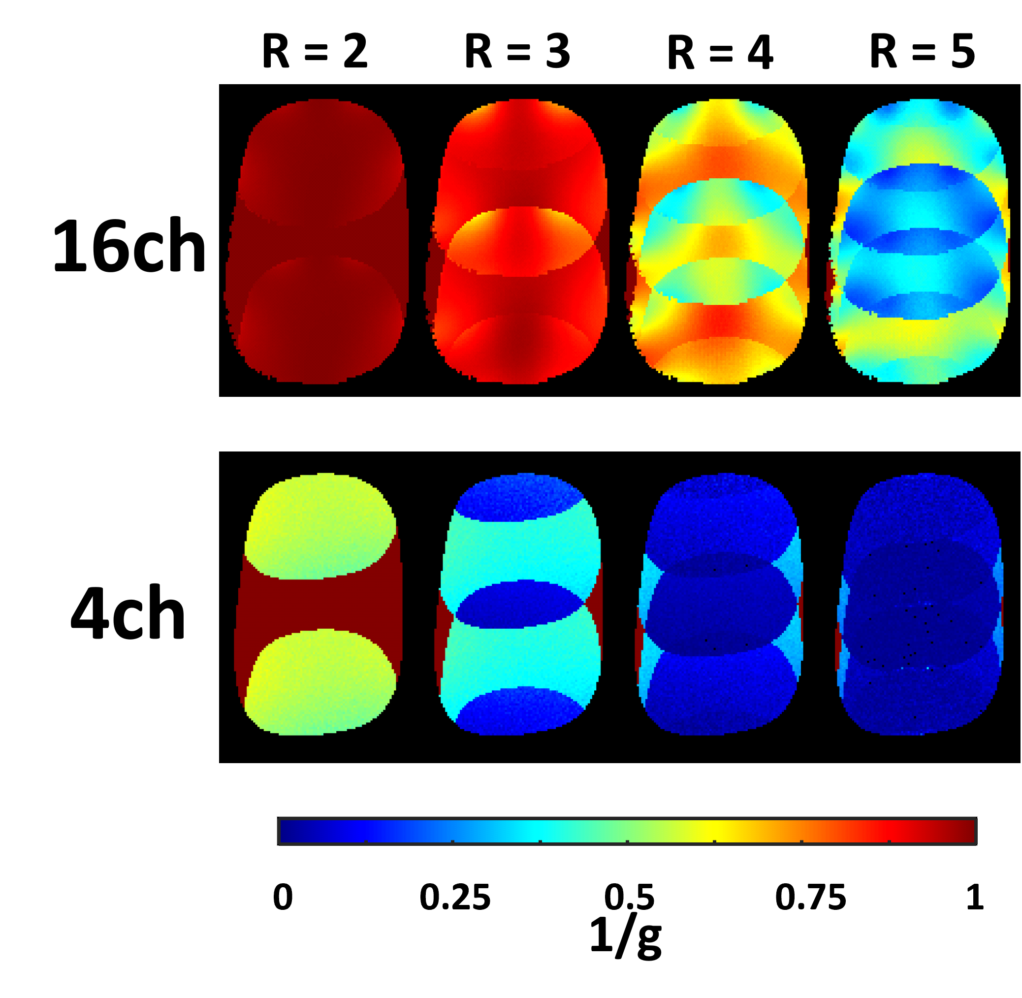
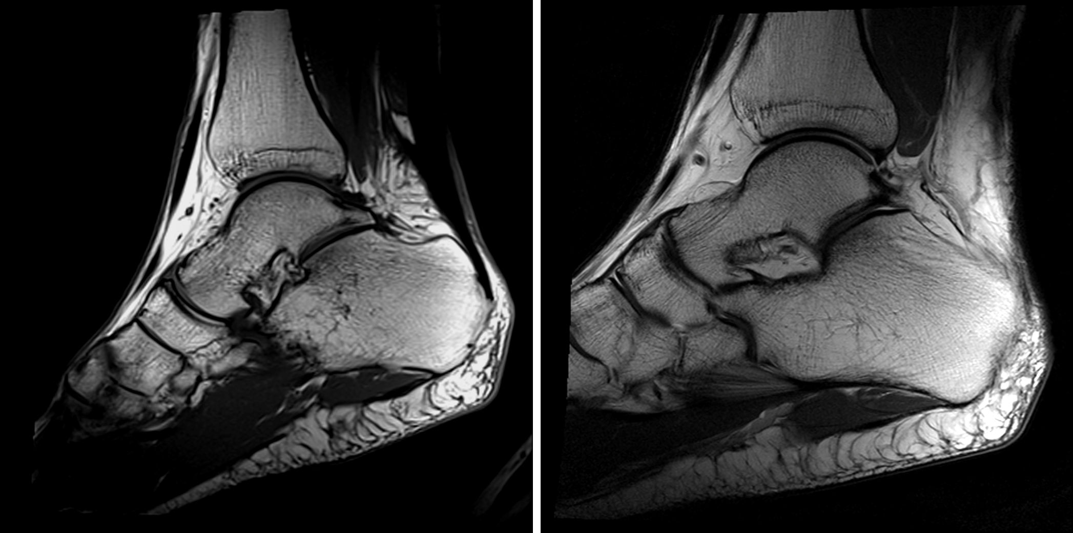
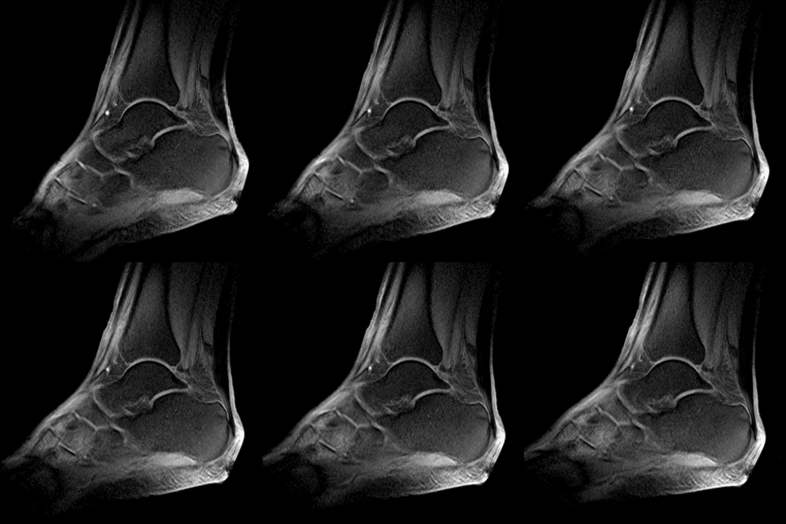
Image acquisition: We used a 1.5T clinical scanner (MAGNETOM Espree, Siemens Healthineers AG, Erlangen, Germany) for image acquisition. A foot-shaped phantom and a PD weighted sequence (TR/TE/α=300ms/5ms/20°, matrix: 256x256, slice: 4mm, BW=150Hz/px) were used to acquire data for pixel-by-pixel calculation of SNR using the Kellman method (Fig.2), calculation of G-maps (Fig.3), and measurement of noise correlation (0V Tx). High-resolution anatomical T1 and T2 images (Fig.4) and accelerated dynamic turbo FLASH (TE/a=/3.99ms/12°, resolution: 0.8x0.8x3mm, BW=130Hz/px; RGRAPPA=3: TR=1220ms) (Fig.5) images were acquired from a healthy volunteer. SNR and G-maps were compared to a 4ch head coil and an extremity coil.
Results
Geometric decoupling of the next-nearest neighbors reached up to -24 dB (average: -15 dB). Active detuning achieved an isolation between the tuned to detuned state of >38 dB. Preamplifier decoupling attained an average value of -22 dB. QU/QL-ratio was measured to be 218/42=5.2 at 63.67MHz.The noise correlation for the 16-channel ankle coil ranged from 7% to 51% (average: 27%). At the angle region the constructed coil outperformed the 4-channel head coil and the birdcage extremity coil by a factor of 2x and 1.3x respectively. The ankle coil enabled dynamic acquisitions with GRAPPA factor 2 and 3.
The RMD did not generate any artifacts in the imaging, which indicates sufficient electromagnetic shielding of the electronic components, cables, and of the actuators.
Discussion
The use of commercially available coils is suboptimal in combination with controlled, passive movements of the ankle joint. Specially developed equipment with adapted coil systems was necessary to improve user-friendliness and workflow, and to obtain reproducible MR images of clinically valuable quality. The combination of the Robotic Motion Device and the dedicated 16-channel ankle coil improved the examination of mechanically guided dynamic imaging of the ankle. The 16 coil elements provided an adequate SNR and allowed accelerated image acquisitions. The combination of these technologies can potentially enable clinicians to detect pathologies that cannot be seen in static MR imaging.Conclusion
The combination of a robotic motion device for controlled passive joint movements and an ankle conformal array for accelerated dynamic MR imaging showed promising initial results for dynamic MSK diagnostics.Acknowledgements
This study was supported by the German Gov’t foundation BMBF (ID: 13GW0398A/B/C)References
[1] Elias I, Abolmaali ND, Lohrer H, Morrison WB, Schweitzer ME, Vogl TJ. MR Evaluation of the Ankle Tendons: Visualization of the Entire Tendon Course via Positioning of the Foot and Ankle using a New MR-compatible Kinematic Device. [Radiology 2003; 229 (P): 655] RSNA, Chicago 2003.
[2] Elias I, Morrison WB, Zoga AC, Raikin SM, Lohrer H. Lateral Calcaneocuboid Ligament Ruptures Imitating Talocrural Ligament Injuries Diagnosed with a Passive Motion Device Using MRI. AJR 2005; 184 (4S): 11. ARRS Annual Meeting, New Orleans 2005.
[3] Elias I, Abolmaali N, Morrison WB, Vaccaro AR, et al.: Real Time Passive Motion of the Musculoskeletal System Using a Motor Driven Kinematic Device During Ultra Fast MRI. ISMRM Meeting Miami, FL, 2005.
[4] Elias I, Zoga AC, Schweitzer ME, Morrison WB, Abolmaali N. Controlled Dynamic Movement of Joints and Spine during Ultra-fast MRI Using a Motor Driven Device: Feasibility and Practical Application. RSNA, Chicago, Nov 2011.
[5] Raikin SM, Elias I, Nazarian LN: Intrasheath subluxation of the peroneal tendons. J Bone Joint Surg Am. 2008 May; 90 (5): 992-9.
[7] Roemer PB, Edelstein WA, Hayes CE, Souza SP, Mueller OM. The NMR phased array. Magn Reson Med. 1990;16(2):192-225. doi:10.1002/mrm.1910160203
[8] Kellman P, McVeigh ER. Image reconstruction in SNR units: a general method for SNR measurement. Magn Reson Med. 2005 Dec;54(6):1439-47. doi: 10.1002/mrm.20713. Erratum in: Magn Reson Med. 2007 Jul;58(1):211-2. PMID: 16261576
Figures